

7.3 Concept Analysis |
143 |
different initial partitions. More sophisticated methods (e.g., based on genetic algorithms) to cope with this problem can be found in the literature.
When a large software system is analyzed, the number of clusters in the (sub-)optimal partition may be big. In this case, it makes sense to cluster the clusters, thus creating a hierarchy of packages. The first step consists of applying the modularization algorithm to the set of all the entities, which are assigned to different clusters. A new higher-level graph is then built by treating each cluster as a single entity. Given two nodes in this higher-level graph, if there exists at least one edge between any two enclosed entities, then there is an edge between the higher-level nodes in the new graph. The clustering algorithm is re-applied to the new graph, in order to discover the next higher-level graph, and so on, until all components have coalesced into a single cluster.
Symmetrically, when the clusters obtained by the optimization of MQ contain a large number of entities, it makes sense to re-apply the clustering algorithm inside each higher-level cluster, until groupings of entities of manageable size are produced. The hierarchy of the packages is obtained as an effect of clustering re-computation within previously determined clusters.
The algorithm described above needs be improved in cases where not only the existence of a relationships is important, but also the number of instances of the relationship and the kind of relationship matter. This is especially true with Object Oriented systems. For example, the presence of an inheritance relationship between two classes may be a stronger indicator of the fact that the two related classes should belong to a same package, than the existence of a dependency due to a method call. Thus, inheritance should be weighted more than dependency. Moreover, the fact that a high number of method calls exists between two classes should result in a stronger relationship than in the case of a small number of calls.
Therefore, the technique described above has to account for the so-called interconnection strength of the relationships: a proper weighting mechanism must be defined for the inter-class relationships, according to the number of instances and/or the kind of relationships being considered.
7.3 Concept Analysis
Concept analysis [25] is a branch of lattice theory that permits grouping objects that have common attributes. Concept analysis has been successfully applied to code restructuring and modularization [24, 50, 71, 75, 88, 94], with functions as the objects, and properly selected function properties as the attributes (e.g., accesses to global variables, accesses to dynamic locations and presence of user-defined structured types in the signature, including the return types). A few survey papers [78, 79, 82] account for the applications of concept analysis to software engineering in general.
144 7 Package Diagram
The possibility to use concept analysis for package diagram recovery descends from its ability to determine maximal groupings of objects sharing maximal subsets of common attributes. In this application of concept analysis, the objects to be considered are the classes of the program, while the attributes are selected among the class properties. The choice of which properties to include in the analysis is quite important and may lead to different results. Examples of class properties that are highly related to the cohesion that packages are expected to exhibit are the following:
User defined types used in the declarations of class attributes, method parameters, return values, and/or local variables.
Method calls.
Relationships a class has with other classes (aggregation, inheritance, etc.).
Informal properties such as words in method identifiers, comments, etc.
The output of concept analysis represents a candidate package diagram for the given program, in that classes are grouped together when they share maximal sets of properties. For example, classes operating on the same, user defined types, calling the same methods, related to the same classes, or including the same descriptive information, are likely to be a cohesive group that can be possibly interpreted as a package of the system.
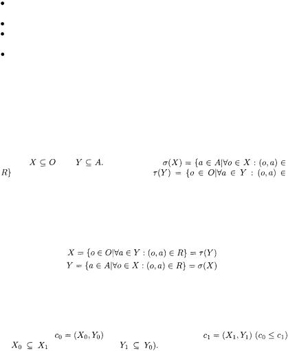
The starting point for concept analysis is a context (O, A, R), consisting of a set of objects O, a set of attributes A and a binary relation R between objects and attributes, stating which attributes are possessed by each object.
Let |
and |
The mappings |
(the |
common attributes |
of X) and |
 (the common objects of Y) form a Galois connection, that is, these two mappings are antimonotone and extensive.
A concept is a maximal collection of objects that possess common attributes, i.e., it is a grouping of all the objects that share a common set of attributes. More formally a concept is a pair of sets (X, Y) such that:
X is said to be the extent of the concept and Y is said to be the intent.
The definition given above is mutually recursive (X is defined in terms of Y and vice-versa), thus it cannot be used in a constructive way (it just helps deciding if a pair (X, Y) is or is not a concept). However, several algorithms for computing the concepts from a given context are available (see below).
A concept |
is a subconcept of concept |
|
if |
(or, equivalently, |
The subconcept relation forms a |
complete partial order (the concept lattice) over the set of concepts [25].
7.3 Concept Analysis |
145 |
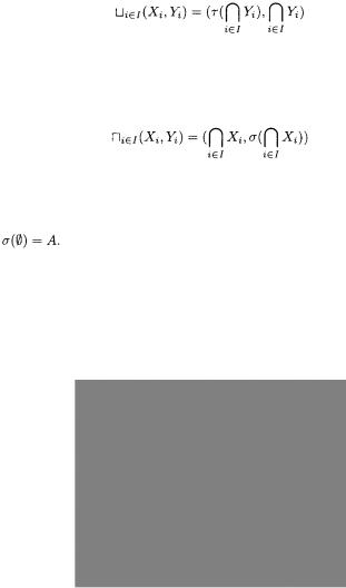
The fundamental theorem for concept lattices [25] relates subconcepts and superconcepts as follows:
The least upper bound (suprermum) of a set of concepts (join operation) can be computed by intersecting their intents and finding the common objects of the resulting intersection. Dually, the largest lower bound (infimum) can be computed as follows:
The steps of a simple bottom-up concept construction algorithm (see [75]) are the following:
1. Compute the bottom element of the concept lattice:  with
with
2.Compute the atomic concepts – smallest concepts with extent obtained by treating each object as a singleton: 
3.Close the set of atomic concepts under join (AtomicConceptClosure).
The procedure AtomicConceptClosure, which computes the transitive closure of the atomic concepts under the least upper bound (join) relationship, is given in Fig 7.5.
Fig. 7.5. Bottom-up concept formation algorithm. Procedure AtomicConcept-
Closure.
A worklist is initialized with all pairs of concepts that are not sub concepts of each other (line 1). Then, the formation of superconcepts is tried, as long as there are pairs of concepts to consider in the worklist. Each such pair gives
146 7 Package Diagram
raise to a unique supremum, computed at line 4. If such a concept has not yet been discovered, it is added to the list of known concepts (not shown) and it is compared with all concepts produced so far. For each concept that is unrelated with the new one (line 7), a pair is generated and added to the worklist. In the end, the transitive construction of all superconcepts, starting from the atomic concepts, gives the final set of all the concepts, organized into the concept lattice.
The key observation for using concept analysis in package diagram recovery is that a package corresponds to a formal concept. Let us consider, for example, the method calls issued inside the code of the classes under analysis. A concept consists of a set of classes performing a set of same method calls, which are not simultaneously made by the code of any other class outside the concept.
An example of such kind of context is given in Table 7.1. The set of objects consists of the three classes  and the attributes are the calls to methods
  Table 7.1 indicates which class invokes which method. After applying concept analysis to this example, the following concepts are identified:
Concept |
indicates that all the three classes call method |
Concept |
|||||
states |
that |
both |
and |
call both |
and |
is the only class calling |
|
both |
and |
(concept |
while no class has the property of calling all |
||||
three methods |
|
|
|
|
|
||
The concept lattice associated with the concepts |
above is depicted |
||||||
in Fig. 7.6 (nodes have the shape used in package diagrams). Edges indicate the subconcept relationships and are upward directed. Inside each concept (package), the names of the classes that have been grouped together are shown, while the related attributes are not indicated.
Concepts are good candidates for the organization of classes into packages. In fact, each concept is, by definition, characterized by a high cohesion of its objects around the chosen attributes. However, concepts may have extents

7.3 Concept Analysis |
147 |
Fig. 7.6. Example of concept lattice, showing the candidate packages.
with non-empty intersections. Correspondingly, not every collection of concepts represents a potential package diagram. To address this problem, the notion of concept partition was introduced (see for example [75]). A concept partition consists of a set of concepts whose extents are a partition of the object set O.  is a concept partition iff:
A concept partition allows assigning every class in the considered context to exactly one package. In the example discussed above, the two following concept partitions can be determined (see dashed boxes in Fig. 7.6):
The first partition contains just one concept, |
and corresponds to a |
|||||
package diagram with all three classes |
in the same package, on the |
|||||
basis of their shared call to |
|
The second |
partition |
generates a proposal |
||
of package organization in which |
and |
are inside a package, since they |
||||
call both |
and |
while |
is put inside a second package for its calls to |
|||
and |
It should be noted that the second package organization permits |
|||||
a violation of encapsulation, since classes of different packages have a shared
method call, namely to |
It ensures that no class outside |
invokes both |
|||
and |
while |
alone can be invoked outside |
This example gives a deeper |
||
insight into the modularization associated with a concept |
partition: even in |
||||
cases in which the only package diagram that does not violate encapsulation is the trivial one, with all the classes in one package, concept analysis can extract