

SpeakingOilGas
.pdfBecause the seismic boat cannot turn quickly, a support vessel is normally kept on standby to alert other recreational, fishing and commercial vessels that a seismic survey is being undertaken. The support vessel is also used to re-supply the seismic boat with fuel and consumables.
Crew changes are made every four to six weeks, and this is usually carried out by helicopter. The typical crew size for a large 3D seismic vessel is 60 personnel, evenly divided between the marine crew and the specialist seismic crew. Surveying continues day and night, so two shifts are required. With the larger, more modern vessels, there is enough space for theatres, gyms, saunas, single or two-person ensuite cabins and life on board is comparatively comfortable.
Land operations
The logistics of land operations can be a more time-consuming and expensive task, particularly in mountainous, jungle or remote desert terrain. In BHP Billiton’s Algerian desert leases for example, the activities take place many hundreds of kilometres from the nearest town. Roads must be made to enable the vibroseis trucks to reach their required locations. The geophones are laid out at specified locations and the recording crew ensures the data is acquired correctly. All personnel need to be supplied with many litres of water a day in summer desert conditions. The base camp for operations may have hundreds of personnel to keep the seismic crew operating.
Overall, the emphasis in data acquisition on land or sea is on maintaining consistency so that changes seen in the recordings result from changes in geology and not from changes in technique.
Seismic processing
Processing centres are found around the world, but tend to be concentrated in cities close to exploration activity such as Houston, London and Perth, Western Australia.
36 |
SPEAKING OIL & GAS |
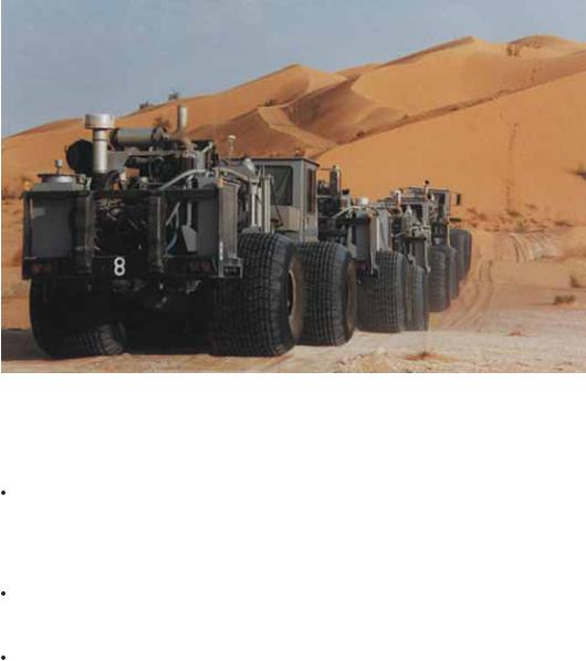
Seismic trucks, Sahara Desert, Algeria
Sophisticated software and specialised skills are required to turn the raw recorded data into the final image of the subsurface geology used by the seismic interpreters to make their drilling decisions.
Amplitude decay — sound waves, like ripples in a pond, spread out, losing energy as they go. The rock layers reflect some of the energy and absorb preferentially higher frequencies. These factors cause the signal to decay with depth. The signal can be boosted, but ambient noise is also boosted.
Diffractions — near surface irregularities cause the sound waves to diffract and scatter, like rain drops on a car windshield scattering sunlight. Filters must be designed to remove this noise.
Multiples — these are a major problem, particularly on marine surveys. The water surface acts like a mirror, reflecting all the upcoming energy from the desired rock-layer reflections back down to generate secondary and tertiary images. In shallower water, trains of multiples are thus generated. Significant effort is required to predict and accurately remove these multiples.
SURVEYS |
37 |

Refraction — when a sound wave passes from a material of one velocity to another it bends or refracts, like light going into water or glass. The amount of refraction depends on the contrast in velocity. In places like the Gulf of Mexico, salt bodies have a velocity often more than twice as fast as the surrounding rock layers. Being irregular in shape, they can bend the sound waves quite dramatically. It can take months of work to build an accurate model of the subsurface velocity which is then used to remove the distortion.
Anisotropy — sound waves can travel faster horizontally compared to vertically due to the layering in the sediments. This causes the sound waves to bend in an unpredictable way. In some cases the velocity may also vary with an orientation that is faster in one horizontal direction compared to another.
Timing errors — on land data, differences in the topography and degree of weathering cause the seismic signal at a given location to be delayed relative to its neighbours. On marine data, tidal changes during the survey are enough to misalign the reflection events. Seasonal changes in water temperature can also influence the data. All these need to be measured and corrected for.
Migration — any non-horizontal reflection will appear mispositioned in space. The steeper the dip and the greater the distance from surface, the larger the magnitude of this mispositioning. A process called migration attempts to reposition the events in their correct locations. The process is sensitive to the velocity of the sound waves and all of the above issues need to be addressed before this vital process can be applied.
Seismic processing software designed to deal with these and other erroneous effects on the data places high demands on computer resources. Indeed, the requirements for seismic processing have been a significant factor driving computer evolution. Some of the pioneering computer companies were set up by geophysical companies to push the boundaries of hardware performance. The demands of image manipulation are now the main drivers of computer hardware and software.
38 |
SPEAKING OIL & GAS |

Seismic without interpretation or annotation or wells
Seismic with interpretation
SURVEYS |
39 |

Seismic acquisition, processing and interpretation probably exceed all other scientific data collection in terms of the amount of raw data collected. The demand for increasingly large 3D surveys, more sophisticated processing sequences and shorter turnaround time means that the traditional tape-to- tape processing is being steadily replaced by huge volumes of disk space measured in terabytes (1000 gigabytes) and petabytes (1000 terabytes).
The sheer volume of seismic data meant that literally truckloads of seismic tapes were used in the past to transport the data from acquisition to processing centre. Modern disk media hold vastly more data than previously, however it will be a while before there is an end to tapes as a storage and exchange media.
Seismic interpretation
The final processed data is generated as a number of three dimensional volumes and turned over to a team of specialists for analysis.
Interpreters map key horizons.
Seismic stratigraphers infer the depositional environment from the shapes of the geological bodies.
Structural geologists recreate the structural history of the data by examining the relative positions of faults, unconformities and in some places the shape of the salt bodies. Salt, being lighter than the surrounding sediments, flows like an extremely viscous fluid pushing up through overlying rock layers. This is slower than glaciers, but it does move over long distances in geologic time. The structural interpretation recreates the geometry of the geologic layers over time, predicting how hydrocarbons may have moved.
Basin analysts use the inferred depositional history and what is known of geothermal gradients to predict where, when and what type of hydrocarbon may have been generated.
Petrophysicists use well bore measurements to tie the seismic data to the well logs.
40 |
SPEAKING OIL & GAS |

Reservoir engineers build detailed models of reservoir properties. With the aid of repeat surveys (called 4D surveys), they also examine how a reservoir is drained and decide on infill drilling.
In better quality data, direct evidence of hydrocarbons can be deduced from subtle changes in the seismic reflection strength (amplitude), particularly as measurements at different offsets can show significant differences in reflection strength depending upon the fluid content of a reservoir.
The bright spot technique, for instance, derives its name from the fact that it shows up on the seismic profile as a visually brighter reflection. Bright spot identification is based on the theory that oil or gas in the pore space affects reflectivity of seismic waves. In other words, there will be an anomalous change of amplitude at the edge of the petroleum accumulation where the wave passes from hydrocarbons back into water-filled pores.
An associated indicator is called a flat spot, where the reflections are returned from a fluid contact. This is more likely from a gas/water interface because there is a much greater contrast between velocities of seismic waves in gas and water than there is between velocities in oil and water. A firmer prediction can be made if two flat spots are detected one under the other. One is potentially a gas/oil contact within a reservoir while underneath may be the oil/water contact.
Nevertheless, apparent direct indicators like bright spots and flat spots can be caused by factors other than hydrocarbons such as coal seams and porosity changes between rock types.
Another technique is called amplitude variation with offset (AVO). This is defined as a variation in seismic reflection amplitude with a change in the distance between the shot point (energy source) and the receiver that indicates differences in lithology and fluid content in rocks above and below the reflecting layer. Interpreters use this effect to try and determine the thickness, porosity, density, lithology and fluid content of rocks.
SURVEYS |
41 |
Seismic interpretation systems are able to store the large volumes of data generated by the seismic survey and quickly manipulate them so that the interpreter can scan through it as horizontal or vertical slices. The systems can be used to generate semi-translucent 3D volumes so interpreters can better understand relationships between the features they are examining. They can change the colour, amplitude and orientation of the data. They can strip away geologic layers to look at the patterns on a horizon of interest. And they can stretch the data from time recording to depth, if this has not been done in the original processing.
Even so, seismic interpretation is subjective, particularly in new areas where there is little or no well control. A number of interpretations can be made from the same data depending on the number and experience of interpreters and the variation in guidelines and exploration philosophies in vogue at the time. It is at this point that a potential target can be condemned by one explorer, yet seized upon and made into a discovery by another.
Despite all the technical difficulties and unknowns outlined above, amazingly detailed images of the subsurface can be made in areas of good signal penetration. Petroleum geologists today have vastly more information available to make their interpretations than their peers in academia or the mining industry. High quality seismic surveys covering thousands of square kilometres allow unprecedented understanding of the geological history to depths of 10–20 kilometres.
42 |
SPEAKING OIL & GAS |

Chapter 3. DRILLING
Once interpretive maps have been completed highlighting prospects worth investigating, the only way to find out if hydrocarbons are present and in commercial quantities is by drilling. This introduces the most colourful side of the industry, both in terminology and activity.
Geologists, geophysicists and drilling engineers combine their professions to produce a well prognosis which is an attempt to predict the stratigraphic column (including the depths to each formation) that will be penetrated by the drill bit. In new areas the prognosis is more difficult than it is in drilled regions where subsurface information is available, but it still serves as a guide to the formations and conditions that may be encountered down the hole.
Prior to 1900 most wells were sunk either by hand digging or by cable tool (percussion) drilling. In the latter method the bit was dropped attached to a cable, raised by a surface winch and dropped over and over again. The weight of the bit penetrated the formation gradually, with pauses
DRILLING |
43 |
from time to time to extract the fragmented rock cuttings from the hole. Percussion drilling in some areas was used until the late 1950s. However modern drilling is by rotary means whereby the bit is connected to lengths of pipe and mechanically rotated on the bottom of the hole.
Rig types
Bottom-supported |
|
Floating |
|
|
|
|
|
|
|
Submersible |
|
Jack-up |
Semi-submersible |
Drillship |
|
|
|
|
|
|
|
|
|
|
Types of offshore drilling units
Essentially all rotary drilling units have the same components and the only real differences in rigs themselves stem from the medium in which they are used.
On land the large rigs can be broken down into a number of loads for transport to and from drilling locations, while smaller rigs are permanently mounted on a truck or trailer. When working in dense jungle or other areas inaccessible by surface transport, a heli-rig is used. It is simply a land rig capable of being broken down to load sizes that can be airlifted to location by helicopter — usually about 2000 kilograms per load.
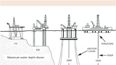
Offshore rigs are of four types — submersibles, jack-ups, drillships and semi-submersibles.
44 |
SPEAKING OIL & GAS |
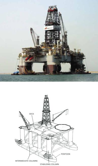
GlobalSantaFe’s GSF Development Driller I, semi-submersible rig
Semi-submersible drilling rig showing the intermediate columns
DRILLING |
45 |