

SpeakingOilGas
.pdfNatural flow accounts for most of the world’s oil production but, as previously mentioned, only a portion of the hydrocarbons are recovered via this means.
Secondary or supplementary recovery is achieved in a number of ways. Re-injection is a method where reservoir pressure is maintained by returning natural reservoir fluids such as water (water flooding) or gas to the producing zone via strategically placed wells in the field that are dedicated to re-injection. This technique bolsters the main (primary) drive as long as possible.
Gas lift (or artificial lift) is also a means of extending natural oil flow. It involves increasing the amount of gas produced with the oil by injecting gas directly into the flowing column in a well rather than into the reservoir. Gas lift is accomplished by using special valves set up at various depths and then controlling the amount of gas entering the flow stream. The increase in gas/oil ratio reduces the pressure needed to drive the oil to the surface.
Pumping is another form of artificial lift and is accomplished in three ways — a beam or rod pump (the familiar oil field ‘nodding donkey’), a hydraulic pump or a submersible electric pump. The latter two pumps are installed in the well bore itself.
Tertiary or enhanced recovery involves oil production only. It is achieved by injecting fluids which are not normally present into the reservoir with the aim of altering the properties of the oil to enable a greater proportion to be produced. Enhanced recovery methods are generally applied after primary and secondary techniques have been exhausted. The methods include injection of miscible fluids like carbon dioxide and nitrogen and injection of complex polymers or steam. Another technique is in situ combustion, particularly for viscous oil. This involves igniting some of the oil in the underground reservoir to heat the remaining oil and render it less viscous and thus more able to flow to the wells.
These tertiary methods can raise ultimate petroleum recovery by 10–20 per cent under favourable conditions.
76 |
SPEAKING OIL & GAS |
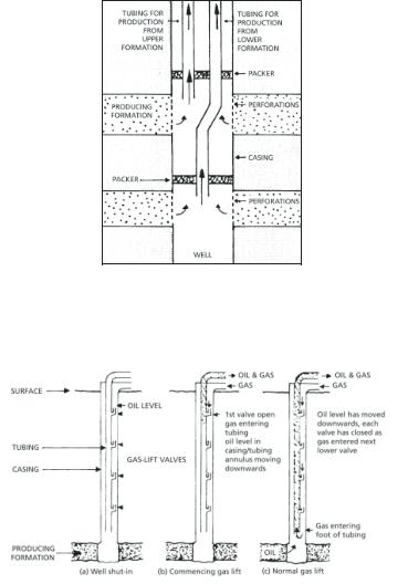
Diagram of dual completion in producing well
Gas lift operation
EVALUATION & PRODUCTION |
77 |
Production hardware
The production process for oil and gas is generally the same onshore as it is offshore and any differences in technique are a matter of economics and designing an engineering solution to best deal with the fluids involved. Space limitations offshore may also influence the process design.
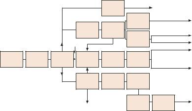
Processing includes six systems — gathering, separation, treatment/ storage, water treatment, safety, and utility handling facilities.
•The gathering system is a series of small diameter pipelines connecting to each wellhead and feeding into the main processing inlet.
•The separation system relies on the fact that oil, water and gas have different densities and will settle into separate layers. Internal devices in the separation vessels assist in speeding up the process.
•The treatment, storage and disposal system for oil and gas is usually split into two streams. Oil leaving the separation system is virtually free from dissolved gas and is termed ‘stabilised’. However, it may still contain water in emulsion form. Further treatment can remove this water using various techniques, including the introduction of chemicals or the use of electrostatic separation.
Gas leaving the separation system is saturated with water vapour and hydrocarbon liquids, with the amount of liquid depending on temperature and pressure. Water is removed with absorbing substances such as glycol. Special membranes remove carbon dioxide, and dehydration enables the capture of sulphur compounds. Nitrogen and hydrocarbon liquids, mainly ethane, butane and propane, are then separated using a refrigeration process until the various components condense out of the gas stream.
•The water treatment and disposal system involves further action on the water to reduce residual oil content to acceptable environmental levels before it is discharged. The methods may include de-aeration, filtration or chemical treatment, with time allowed for settling out of the two phases.
78 |
SPEAKING OIL & GAS |
|
|
|
GAS |
Flare system |
|
|
|
|
|
|
|
|
|
|
|
|
|
|
Compression |
Pipeline |
|
|
|
|
|
|
|
|
|
|
Gas |
Gas liquids |
|
|
|
|
|
dehydration |
recovery |
|
Gas lift |
|
|
|
system |
system |
|
|
|
|
|
|
|
||
|
|
|
|
|
Compression |
Gas re-injection |
|
|
GAS |
OIL |
|
|
|
|
Gathering |
Separation |
Oil |
Storage |
Pumping |
Pipeline |
|
|
|||||
Reservoir |
treatment |
|
||||
system |
system |
system |
system |
|
||
|
system |
Tanker |
||||
|
|
|
|
|
||
|
|
|
|
|
|
|
|
|
WATER |
Oily water |
|
|
|
|
|
|
Filtration |
De-aeration |
|
|
|
|
|
separation |
|
||
|
|
|
system |
system |
|
|
|
|
|
system |
|
||
|
|
|
|
|
|
|
|
|
|
WATER |
|
Water |
|
|
|
|
|
|
Pumping |
|
|
|
|
|
|
injection |
|
|
|
|
|
|
system |
|
|
|
|
SEA |
|
system |
|
|
|
|
|
|
||
Possible production systems on an offshore platform
•The safety system includes installation of alarms, automatic shutdowns, back-up units on important equipment, exhaust (flare) stacks and fire fighting equipment, plus strict administrative procedures and frequently practised emergency containment and evacuation plans.
•The utility systems include power generation and facilities for normal services, all of which can be, and frequently are, powered by the gas or oil being processed in the plant.
EVALUATION & PRODUCTION |
79 |
Facilities design and layout
Onshore, the individual production wellheads on a field are connected by gathering pipelines to a main processing plant or to individual storage tanks if the field is small. After processing, the oil is transported either by truck, tanker or pipeline to a refinery. Onshore facilities are placed as convenient and in accordance with any civil planning and environmental considerations.
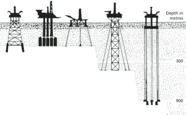
STEEL |
CONCRETE |
FLOATING |
GUYED |
TENSION |
PILED |
GRAVITY |
|
TOWER |
LEG |
Some examples of production platforms
Depending on the volume, gas associated with oil production is either re-injected into the reservoir for pressure maintenance or processed and sent to market via pipeline. Small amounts of the gas can be used to generate power for the production facilities. Flaring unwanted gas is now a rare occurrence, especially on a long-term basis, as most authorities and companies view this as wasting a valuable asset. There are also environmental considerations to do with greenhouse effects and any flaring generally requires a special permit.
80 |
SPEAKING OIL & GAS |
BHP Billiton-operated ‘Griffin Venture’, offshore northwest Australia
|
FLOATING CRUDE |
|
PRODUCT HOSE |
BRIDGE & |
HELIDECK |
CONTROL |
SHUTTLE |
ROOM |
|
FLARE |
OFFTAKE TANKER |
|
HAWSER |
UNIVERSAL |
MOORED STORAGE/ |
JOINT ASSEMBLY |
PRODUCTION TANKER |
RISER |
|
CHAIN TABLE |
|
ANCHOR CHAINS |
|
|
SUBSEA |
|
WELLHEAD |
ANCHORS |
|
|
FLOWLINES & |
|
CONTROL UMBILICAL |
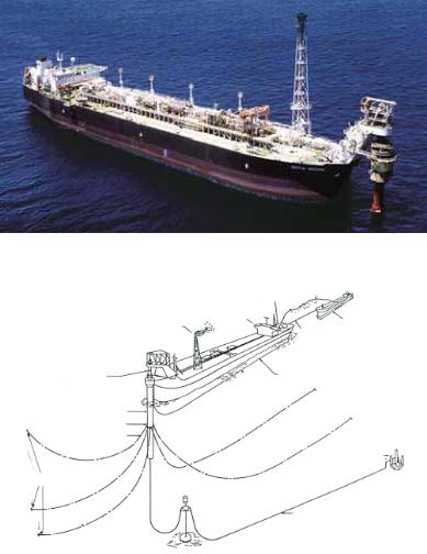
A floating production storage and offtake facility (FPSO)
Offshore, there are various ways of tackling the production layout, space being at a premium on a production platform or production vessel. For medium to large fields it is common to have one or more fixed platforms which house all the wellheads and the processing equipment, plus accommodation for the field workers. A pipeline can then be run to shore to permit more extensive processing and storage and/or distribution. In some isolated oil fields, a short pipeline may be laid from a platform to a nearby buoy mooring system which is used to load the oil directly into offtake tankers.
EVALUATION & PRODUCTION |
81 |
Douglas complex at BHP Billiton-operated Liverpool Bay Development, Irish Sea
Offshore platform system
82 |
SPEAKING OIL & GAS |
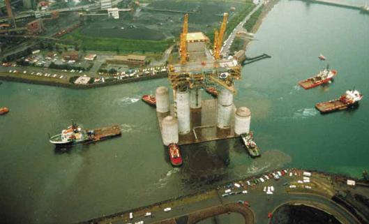
West Tuna concrete gravity based facility being towed out from Port Kembla to Bass Strait
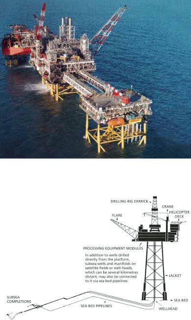
Platforms vary in size, shape and type depending on the size of the field, the water depth and the distance from shore. Most common is a steel structure with piles sunk into the sea bed, but there are also concrete and/or steel structures that are held onto the sea bed by their own weight (gravity structures) or converted jack-up exploration rigs that stand on the sea bed. Other systems employ floating vessels (usually ship-shaped) known as floating production, storage and offtake facilities (FPSO). Another type is a tension leg platform that is tethered to the sea bed by vertical cables and yet another is the guyed tower which is supported upright by radiating cables anchored into the sea bed, acting much like the guy ropes of a tent.
In fixed platforms, the legs have a primary function of supporting the deck and its load of processing facilities. The leg structure also surrounds and protects the well conductors (hence the term jacket). Some fixed platforms, particularly the concrete gravity type, also contain oil storage tanks in their bases or in the column legs.
If the water is shallow and land (or another platform) is nearby, small platforms may be used with the main processing facilities located ashore (or on a centrally-located master platform).
EVALUATION & PRODUCTION |
83 |
In other cases, subsea production units are used. These sit on the sea bed and feed oil and gas into fixed platforms or floating production and storage units via flexible flow lines and buoyed marine risers. The floating facility can range from a vessel just for storage purposes to a disconnectable, self-propelled tanker. Processing is still done on the facility, not on the sea bed, although subsea processing is a developing technology. The subsea units may be open to the sea (a wet tree) or, in the past, encapsulated in a chamber under which pressure is kept at atmospheric levels to allow operators to enter and work under normal conditions (a dry tree). Dry chambers permitted manual intervention beyond diver depths and opened the door to deep water development.
Production engineering is continually pushing the frontiers of technology, especially in offshore applications. At the same time, the best designs include equipment and systems that are as simple as possible to improve reliability and avoid potential flow problems. Robust system design enhances economic performance. There is also consideration given to geographic location. If the field is remote from infrastructure, such as West Africa or the North West Shelf off Australia, construction vessels have to be brought in especially and this may increase the overall cost of the project. On the other hand, in the active Gulf of Mexico or North Sea, many construction vessels are employed in the region and mobilisation costs to a project are much less.
As the industry tackles deeper and deeper water, FPSOs connected to subsea wellheads are replacing fixed platforms as the main development technique. FPSOs allow the facilities to be placed over the field. Platforms in shallow water often have longer tie-backs, while the reservoirs on the edge of the continental shelf are developed subsea. Oil flow lines between the wells and the production facilities can be up to 30 kilometres long and must combat pressure drop-off, heat loss and an increase in oil viscosity. For gas, the flow lines can be much longer (up to 200 kilometres) allowing production to flow directly to a shore plant rather than an offshore facility. In some instances artificial islands have been created for shallow water and Arctic applications.
84 |
SPEAKING OIL & GAS |
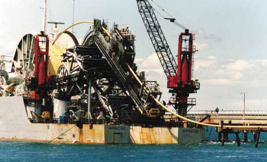
‘Apache’ reel pipelay barge
There have also been recent advances in the remote control of subsea wellheads. Undersea umbilicals carrying the hydraulic, power and electronic communication cables can be up to 150 kilometres long. In the Arctic, work is being done to perfect an umbilical system that runs under the ice to connect with and control a subsea system 400 kilometres away. Steel tubes are replacing the thermo-plastic hoses of earlier umbilical design. Another emerging technology is the development of autonomous control systems where the umbilicals only carry the communication cables, and the power for operating the subsea valves is actually generated at the wellhead. Electric trees are also being developed for long distance and very deep water application.
An alternative technique is the use of remote controlled buoys stationed in the ocean above the subsea system, such as the East Spar field off Western Australia. However these buoys are best for relatively short distances from the shore line. For ‘over the horizon’ applications, satellites are needed as relay stations to bounce the control signals. In addition, the logistics of supplying chemicals such as the injection of glycol or methanol at the wellhead to improve the oil flow rate from the subsea wells is more difficult with a remotely controlled buoy system.
EVALUATION & PRODUCTION |
85 |