

SpeakingOilGas
.pdfBit types
Drill bits can be divided into several classifications.
The rolling cutter bit (or tri-cone bit) for rotary drilling was first successfully designed by Howard Hughes in 1909. It has hardened steel or tungsten carbide teeth of varying lengths and spacings, mounted on three roller cones. The cones are designed to attain maximum cutting rate without causing the teeth to clog.
For soft formations the teeth are long and widely spaced and the cones are offset such that their axes do not intersect at a common point. This offset produces a gouging action on the formation as the bit is rotated.
For progressively harder formations the teeth are shorter and more closely spaced, while the cone offset is made less and less until, for very hard rock, there is no offset at all. These bits rely on destroying the compressive strength of the rock being drilled.
The diamond bit, adapted from the mining industry, imparts a grinding action as the drill is rotated. The bit itself consists of industrial diamonds embedded in a metal matrix. It is long-lasting in all but the hardest formations, thus reducing the number of bit changes while drilling.
Diamonds are also used in core head bits which have a hole forged through their centres allowing a core of rock to pass through into a core barrel mounted directly on the drill pipe behind it.
The polycrystalline diamond compact (PDC) bits have come into use in the last 15 years or so and have dramatically increased penetration rates. PDCs are very durable man-made diamond cutters set into a body to produce a very aggressive cutting action.
As mentioned in the previous section, a relatively recent evolution is the use of downhole motors (and also turbines) attached to the drill string to turn the bit. The power to rotate is supplied by the circulatory drilling mud and it requires a greater pumping effort from the surface than in conventional rotary drilling. The drill pipe itself is also rotated slowly
56 |
SPEAKING OIL & GAS |
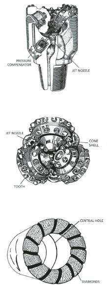
Rolling cutter drill bit (tri-cone)
Tri-cone drill bit (end view)
Diamond core bit
DRILLING |
57 |
and independently from the bit to prevent sticking. Generally mud motors rotate at 150–250 rpm, while turbines can rotate at 2000 rpm and are used when penetrating hard rock.
Hole sizes
The diameter of the drill bits used, and thus the hole itself, becomes successively smaller as the well is deepened. There are no hard and fast rules relating hole depth to bit sizes because much depends on the stability of the formations being drilled and the target depth of the well.
Nevertheless, it is usual to run through a series of sizes beginning with the spud in or surface bit of 36 inches in diameter for offshore wells and 26 inches diameter for land wells. Drilling then progresses through diameters of 26 inches, 17½ inches, 12¼ inches, 8½ inches, down to 6 inches.
In most wells the hole is cased (lined) with steel pipe to prevent caveins and to retain circulation of drilling fluid. The casing is inserted prior to every bit diameter change and the casing sizes correspond to the bit sizes just mentioned: 40 inches or 30 inches for surface (conductor) casing, 20 inches, 133/8 inches, 95/8 inches down to 7 inches, the latter sometimes called a liner or production tubing if the well is a development well.
In slim hole drilling, diameters usually begin at 10 or 8 inches and end at between 5½ and 3 7/8 inches. Early slim hole work was limited to probing relatively shallow targets, but advancing technology and the use of special high-strength drill string able to withstand the high torque forces involved in rotary drilling now enables the bit to reach depth of 3000 metres and more.
Casing
Casing is made up of lengths of steel pipe screwed together, much like drill pipe, which lines the well and acts as a pressure vessel establishing barriers between different producing formations and the surroundings.
The surface, or conductor, casing is anchored to the wellhead and each successively smaller casing size is ‘hung’ from the preceding one as the
58 |
SPEAKING OIL & GAS |
hole is deepened. Usually casing is cemented into place against the well sides by pumping cement under pressure down the centre of the pipe and back up the outside. When set, the cement casing shoe left at the bottom of the well is drilled out, and drilling into new, deeper formation continues.
A specialised form of casing can be manufactured with a diameter profile in the form of two D shapes. This is then pushed down over a wedge placed in the bottom of the hole to drive the two D sections apart making an inverted Y shape. This is used for drilling two lateral (directional) wells from the same location.
Drilling fluid
Drilling fluid is often referred to as drilling mud — a term relating to earlier times when water used to help drill the well became mixed with drill cuttings from downhole to produce a muddy liquid. At first the fluid was discarded, but then explorers found the drilling was easier when using this natural mud. The discovery sparked experiments into variations of drilling fluid. Today muds can be divided into several categories.
Water-based muds (fresh water and salt water) can be simple clay-water mixes, clay-water plus chemical additives, or numerous other combinations. The most commonly used clays are bentonite or montmorillonite, both of which are sodium aluminium silicates that expand to about 10 times their original volume when mixed with water.
For some operations (such as high inclination wells where there can be torque problems on the drill string as well as a danger of hole collapse) and in some geological formations (such as water-reactive shales), water- in-clay is not appropriate because it can destroy permeability and prevent accurate evaluation of a reservoir formation.
Sometimes specialised chemical mud, such as potassium chloride and polymer solutions, is used to counter these difficulties.
Another category is oil-based mud. This can be an oil-in-water or water-in-oil emulsion. The oil used today is diesel, synthetic or pseudo (ester).
DRILLING |
59 |

There are stringent conditions attached to the use of drilling mud, including strict regulations on the disposal of used materials. In the marine environment the spent mud is sometimes stored in containers and sent to shore for disposal, or it may be re-injected into a higher formation or into a dedicated hole already drilled for that purpose.
In some circumstances compressed air, or foamed air, or an inert gas like nitrogen is used as the drilling fluid to prevent damage to a water-sensitive formation or when there is a risk of losing mud into a porous formation.
Drilling fluid has five important uses.
It can be weighted to prevent high pressure formation fluids downhole from entering the well. Usually the weighting material used is barite, a dense, heavy sulphate of barium. However, care must be taken with the mud weight. If it is too high the drilling fluid may break down the formation and escape into it. If it is too low there is a danger of the well being under-pressured and this could potentially result in a blowout. Having said that, there are some circumstances when using air or nitrogen as the circulating fluid, that the well is deliberately drilled underbalanced. This allows formation fluids to escape up the well to the surface where the flow is continuously monitored to detect hydrocarbons. However extreme vigilance and great control is needed to prevent a sudden inrush that might cause a blowout.
It cools and lubricates the bit and the drill pipe.
It acts as a carrier to flush drill cuttings up out of the hole, thus keeping the bit clear and allowing geologists to examine the formation being penetrated.
It coats the hole with a thin layer and acts as a semi-permeable membrane which prevents loss of mud into all but the most porous formations being drilled.
It prevents caving of loose formations.
60 |
SPEAKING OIL & GAS |
In recent times an additional use for drilling fluid is to transmit data up and down the well during a drilling operation. The messages are sent as coded pressure pulses that change the settings of the mud motor or the logging tools. Data from the tools is sent back up the hole the same way and decoded at the surface. During exploration drilling this enables geologists and engineers to get data quickly to enable continuous monitoring and adjustment of the program. During development drilling it can be used to provide an accurate ‘fix’ on the location of the bit at all times and make corrections as necessary.
Logging
The purpose of logging a well is to compile a comprehensive record while it is being drilled and immediately after it has reached its total depth. In this sense cuttings and core samples can be included in the category as well as the various electronic devices used to identify the formations and their properties encountered downhole. Three types of information are obtained through logging methods: rock type and porosity, fluid content of the pores, and mechanical and fluid flow conditions of the well.
Mud logging includes a routine geological examination of the drill cuttings as they are flushed from the hole, plus a comprehensive record of the variations in drilling rates, the variations in mud pumping pressure, the depths of formation changes and an analysis of the mud properties, including hydrocarbon content measured by a gas detector. Any oil in the cuttings causes them to fluoresce under ultraviolet light.
Coring is usually restricted to a reservoir zone or to a section of interest encountered during drilling. Core is collected in a core barrel, which is a cylindrical tube about 20 metres long mounted just above the special coring bit. Once brought to the surface, core is examined on site by a geologist and then sent to a laboratory where porosity, permeability, hydrocarbon saturation, water saturation and detailed lithology (rock composition) are determined.
DRILLING |
61 |
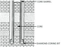
Taking a core sample
A variation of the technique is side wall coring. This is normally done after electric logging to take a sample from zones not evaluated by normal coring methods, but picked up on the log charts as sections of interest. Acore gun containing up to 60 small core barrels about one inch in diameter is lowered into the hole. The barrels contain an explosive charge and are fired electronically from the surface.
The charge drives the barrel into the side of the hole at the required depth and is retrieved by wire rope attachments when the gun is withdrawn. A core obtained in this way has a number of disadvantages in that the explosive force often destroys the texture of the formation sample and, because it is collected from the wall after drilling, it often has pore contents completely altered from the natural state. Nevertheless it is better than no core at all.
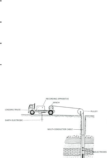
Electric logging is accomplished by lowering instruments called sondes down the well. Each type of sonde measures a different physical property of the rocks that have been drilled, such as electrical resistivity, self potential, natural radioactivity, sonic velocity and induced radioactivity.
Hydrocarbons in the rock are detected directly by an increase of resistivity when compared to the same rock containing water. They are indirectly detected by the various ways in which the responses of the sondes are caused to deviate from normal.
62 |
SPEAKING OIL & GAS |
Electric logs measure the resistivity of the rock and also determine rock type. In general, shale has a low specific resistivity, while limestone and sandstone resistivity is relatively high. Oil and gas within a rock will increase resistivity because they are non-conductive materials.
Nuclear logs measure gamma rays and thermal neutrons and can be used to determine porosity (including fractures) and lithology in a given formation. They are also the only porosity determinants which can be used in a cased hole.
Acoustic logs measure the velocity of sound within the formation in the same way as seismic surveys on the surface detect changes in formations. Acoustic logging is mainly used for porosity determinations and to help in differentiating gas-bearing zones from liquid-bearing zones.
Other logs are run specifically to assess mechanical and fluid flow conditions down the well. They include a calliper log (which measures well diameter), a cement bond log (which measures strength and bonding of cement to casing), a temperature log (which detects the top of the cement column outside the casing because heat is given out when cement sets), and the dipmeter (which measures the formation dip relative to the well), and a compass to determine the well orientation.
Electric logging
DRILLING |
63 |
In earlier days the logging operation was performed separately to drilling. Wells were drilled to a given depth before the drill string was hauled out and the logging tools lowered to take their readings. This is known as wireline logging. More recently the logging operation is accomplished while drilling. The well is drilled to the reservoir or inquiry depth and then the logging tools are sent down to sit behind the bit and the motor. This technique is known as formational evaluation while drilling (FEWD). It provides immediate detailed information about the well and the formations it is passing through.
Thus the ‘business end’ of the drill string starts with the bit and its drive system (the motor, which can be 10 metres long and uses the hydraulics of the drilling fluid to impart a rotation to the bit). The survey package (compass and orientation tools) come next and make up another 10 metre long section. Finally the formation evaluation tools make up the third 10 metre long package and contain gamma ray, resistivity, neutron density, acoustic, calliper and formation pressure tools.
One of the original and still the most important uses of logging is the correlation of equivalent strata from one well to the next, allowing accurate subsurface plotting. This in turn helps determine the formations present relative to other wells. It also indicates whether a well is within a particular geological structure, whether a well has reached a known horizon, the presence of faults and the existence of dips, folds, unconformities, thickening and thinning of formations.
Testing
Notwithstanding all the logging techniques, the final confirmation of the presence and character of hydrocarbons is by producing a sample from the reservoir formation. There are two methods of obtaining such a sample, and both depend on allowing the natural pressure of the reservoir to drive the formation fluids to the well collection point.
A wireline formation interval test involves lowering a test chamber on the end of a wire to the depth of the reservoir and sealing it against
64 |
SPEAKING OIL & GAS |
the well walls using expanding rubber packers above and below. Pressure inside the chamber is atmospheric and a valve assembly, when opened, allows reservoir fluids to flow naturally into the chamber. If there is no flow, a shaped charge is detonated, piercing the formation and opening a flow channel to the chamber.
The volume collected in these tests is small (about 10–15 litres), but it does give an indication of the formation fluids in the reservoir. The test also records pressure of the incoming fluid and some general extrapolations can be made about flow rates. The wireline test is particularly useful in locating hydrocarbon/water contacts and the extent of transition zones.
A drill stem test is more expensive and involves the lowering of a test tool into the well on the end of drill pipe. Packers again isolate the section to be tested and, when the valve is opened, the reservoir fluid is allowed to flow into the drill pipe. It is then recovered when the pipe is pulled out at the end of the test. Alternatively the hydrocarbons may be allowed to flow to surface in a full production test where they are controlled via a series of chokes of different sizes. Pressure and volume of fluids are measured. Oil is collected, while gas is flared.
An open hole test is one that is done on a part of the hole that has not been cased. In a cased hole the test is conducted through perforations shot through the steel walls at the level of the reservoir zone.
Often the test will be shut in after a time to allow the pressure in the reservoir to build up again after the initial flow. Then it is reopened for a second and even a third measurement. Continuity of pressure during a test run and rapidity of pressure build-up between tests give some indication of the permeability of a reservoir and its potential performance in full production mode.
Occasionally, when the discovery is small or marginal, companies will run a long-term production test, stopping and starting the well flow over a period of months to better determine the economics and overall viability of a full development program.
DRILLING |
65 |