

SpeakingOilGas
.pdfJack-up rig — development drilling at John Brookes gas field, Carnarvon Basin, offshore Western Australia
Courtesy of Santos
Elevation of a jack-up drilling unit
46 |
SPEAKING OIL & GAS |
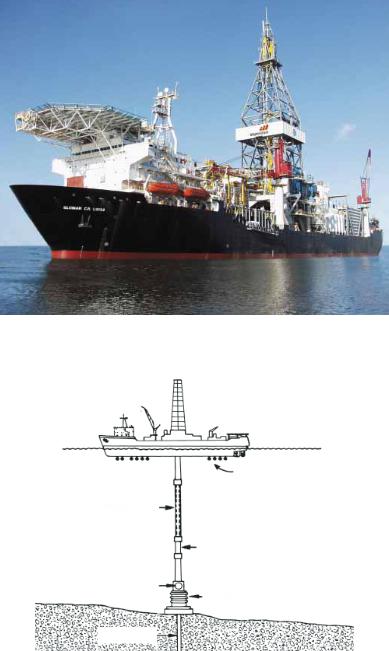
‘CR Luigs’ ultra-deepwater drillship
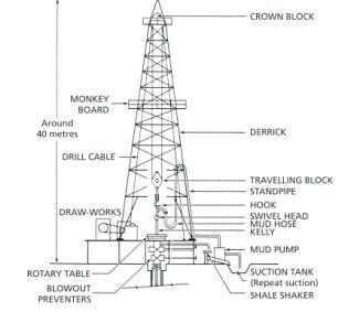
THRUSTERS
TELESCOPING JOINT
RISER
BALL JOINT
BLOWOUT PREVENTER
DRILL HOLE
A dynamic positioning offshore drillship
DRILLING |
47 |
Submersibles are fitted with ballast tanks so they can be floated to shallow water locations, then ballasted to sit on the sea bed or lake bed to provide a stable drilling base.
Jack-ups arrive on location (usually towed by tugs) and mechanically jack their legs down to the sea bed, raising their hulls clear of the water for drilling mode. They are usually used in water depths up to 150 metres, although some of the larger units can drill in up to 300 metres.
Drillships are ship-shaped vessels usually with the drilling derrick placed amidships to drill through a central hole (moonpool) in the hull. Some early vessels were also equipped to drill over the side with the derrick mounted on rails so it could be skidded across the deck. The vessels have their own propulsion, although a variation — the drilling barge — does not have its own locomotion and has to be towed.
Drillships are either anchored or kept in position by a dynamic positioning system which employs computer-controlled propellers along the hull to continually correct drift in any direction. These vessels are used in medium to deep waters, but suffer the usual ship instability in rough weather.
Semi-submersibles are mobile vessels with superstructures supported by columns sitting on hulls or pontoons ballasted below the depth of wave action for drilling mode. For transport mode the hulls are deballasted to the surface. Anchoring can be conventional or via dynamic positioning. Some semi-submersibles have their own locomotion, but many are towed or placed on a barge (especially for long distance moves). These vessels are remarkably stable in rough weather and can be used in medium to deep waters.
Rig systems
No matter what the transport or carrying mode, a rotary drilling rig has five main systems — hoisting system, rotary system, circulation system, power system and blowout prevention/safety system.
48 |
SPEAKING OIL & GAS |
Drilling system
The hoisting system consists of a winch (draw-works) on the rig floor. A wire rope (drilling line) is spooled around the winch drum and is run up to the top of the steel derrick, over the crown block and down to an attachment on the travelling block. This latter has a hook for attaching the drill string via a rotary swivel.
The draw-works are controlled from the rig floor and are used to raise and lower drill pipe, casing and tubing, or any other equipment run into the well. The exceptions may be logging tools. These are often run on a separate winch as a separate operation to drilling, although in modern systems they may actually be mounted in the drill string just behind the bit to enable a continuous logging record to be kept while drilling.
DRILLING |
49 |
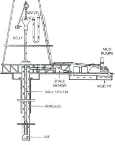
The mud or circulatory system
The rotary system has three main components. First is the rotary swivel for suspension of the drill string to the travelling block. Second is the rotary table located in the rig floor and turned mechanically. Its speed and direction is controlled by the driller. The third item is the kelly, a hexagonal or square hollow pipe about 15 metres long which is attached to the rotary swivel at the top and to the drill pipe at the bottom by tapered screw threads. A piece called the kelly bushing fits into the rotary table so the rotary motion can be transferred from the table to the drill pipe via the kelly. The kelly bushing runs freely up and down the kelly, but cannot rotate independently of the kelly.
Another method of rotating the drill string is a top drive system. This involves hanging a motor from the hook and connecting it directly onto the drill pipe from above. It imparts the rotation without the need for a kelly or rotary table. The method promotes faster drilling and is particularly advantageous during directional drilling programs.
50 |
SPEAKING OIL & GAS |
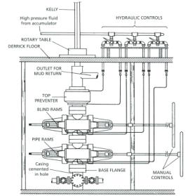
Blowout preventer stack
An additional item in offshore drilling is the marine riser which is a large diameter tubular connection between the rig and the blowout preventer on the sea floor. It is a conduit for the circulation of drilling fluids as well as a guide for running drill pipe and casing. It is fitted with a giant shock absorber called a telescopic joint to allow for the vessel’s movement on the sea surface and it can be quickly disconnected if sea states become too rough for drilling to continue.
The circulation system pumps drilling fluid down the well and consists of mud pumps, suction and storage tanks for the mud itself, a stand pipe which runs up the derrick, a kelly hose connecting the stand pipe to the swivel and a return mud line below the rotary table which returns mud from the well to the shale shakers. The latter item removes the drill cuttings before the mud is sent to the mud tanks for further cleaning by de-sanders and de-pitters to remove the finer debris before recirculation.
DRILLING |
51 |
The power system to operate the rig is either a diesel motor via a direct drive compound system, or (particularly offshore) a direct current electric drive.
The blowout prevention system consists of a series of hydraulicallyoperated valves and pipe rams which are open to allow the mud to circulate during drilling, but which can be quickly closed around the pipe if excessive pressure (a kick) enters the well and threatens to circulate during drilling. If a kick occurs (i.e. excessive pressure from the formation being drilled suddenly entering the well), the pipe rams are closed to prevent this overpressure reaching the surface out of control. The last line of defence in such an emergency are the shear rams which, if necessary, cut right through the drill string and seal the well completely.
Well types
Petroleum industry wells are of three types — wildcat, appraisal and development.
A wildcat is the first exploration well in a new or previously undrilled target. The term seems to have originated from 19th century drilling in the backwoods of the USA where drillers reported wildcats (pumas perhaps) lurking in the vicinity. If the well is the first in a completely new region where there are no close reference points, it can be called a rank wildcat.
Appraisal (sometimes called delineation) wells are drilled as follow-up exploration wells on structures where wildcats have been successful. They are often located to try to provide a rough outline of the field and evaluate its various parameters.
Development (or production) wells are drilled once the discovery has been appraised and judged economically viable. They are drilled specifically to tap the hydrocarbons at definite places in the reservoir.
On some occasions during a drilling program only a small diameter hole is required as an initial exploration tool because it is cheaper, or because conditions deem it more practical. This is referred to as slim hole drilling.
52 |
SPEAKING OIL & GAS |
Another category of well — which can be a wildcat, appraisal or a development type — is the directional well. Depending on the purpose, it can be inclined at various angles up to and exceeding the horizontal, by introducing a bias down one side of the hole which causes the bit to deflect away from the vertical. The early method involved placing an angled length of metal called a whipstock downhole to act as a wedge to change the bit direction.
In recent times a technique known as geo-steering has been introduced for directional wells. Instead of using a whipstock to change the well direction, modern techniques employ steerable motors mounted just behind the bit. They are powered by the hydraulic force of the mud circulating down the hole to turn the bit independently of the drill string (like the force of wind turning the blades of a windmill). The assembly includes a bend at the motor bearing housing so that the bit points at an angle relative to the well centre-line (typically 0.5˚–2˚). This allows the trajectory of the well to be changed when the bit is advanced by using the weight of the whole assembly pushing down on it, and is called sliding. In other words, the mud motor powers the bit so the drill string can be advanced without pipe rotation.
An even later variation of this technique is the rotary steerable system in which a sleeve with several hydraulic rams attached is mounted behind the bit. A pulse sent down through the mud tells onboard computers what rams to push in order to move in the desired direction. Changes are achieved by the rams jamming against the side of the hole, thus pushing the bit off in the opposite direction. The advantage of this system is that the drill pipe can be rotated in the hole independently of the mud motor rotating the bit. This enables a continuous operation and provides more control as opposed to the sliding system which must advance in stages, i.e. slide, rotate the drill string, slide, rotate the drill string until the desired new angle is achieved.
DRILLING |
53 |
A relatively new directional drilling system is known as coiled tubing drilling. The steel drill string is a continuous piece of thin steel tubing wound onto a reel or spool. During drilling the tubing, with bit attached, is progressively wound off the spool and into the hole via a gantry erected over the wellhead. The technique does not require a drilling derrick. The bit is driven by a mud motor or turbine, but the steel tubing itself is not rotated. The flexibility of the tubing enables the bit to be steered around tight bends to reach and stay within very narrow reservoir formations. Coiled tubing is generally used to probe various formations and can be directed in any number of directions from a selected point in wells already drilled by conventional means. It is often used to enhance production from existing producing wells by accessing reserves nearby.
Overall, directional drilling may be used to reach an offshore target from an onshore location (such as the Wytch Farm field in southern England which extends out under Poole Harbour) or to reach outlying parts of a field from a central platform offshore, or to kick off in several separate directions from a single surface wellhead in onshore work. It might also be a deliberate ploy to sidetrack around a lost bit stuck in the original well, or perhaps to seek a new part of the reservoir after the bottom of the original well has watered out and is no longer capable of producing oil. The extreme case is a well which is actually horizontal by the time it enters a reservoir. This exposes a longer section of the well to potential production (particularly in thin petroleum-bearing formations) than a normal vertical or moderately inclined well.
The term long reach well (or extended reach well) is used when the ratio of vertical depth of the target formation versus the lateral extension from the well head is biased to the extension. These wells (usually offshore) can be drilled into a target up to 10 kilometres away from the rig or platform.
54 |
SPEAKING OIL & GAS |
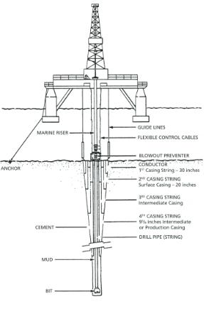
Multi-casing oil well completion
DRILLING |
55 |