

Multidimensional Chromatography
.pdfMultidimensional Planar Chromatography |
181 |
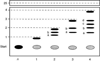
Figure 8.10 Separation of polyphenolic compounds by BMD separation.
Bivariate multiple development (BMD) with a mobile phase gradient of decreasing ST is preferable for the analysis of less complex mixtures of wide polarity, because the complete chromatographic separation finally obtained can now be detected as a single chromatogram. In BMD, the first development is performed over the shortest distance by using the mobile phase system with the greatest ST; the development distance is increased and the ST is then reduced with each subsequent development until the final development is performed over the longest distance with the weakest mobile phase. By use of BMD with a mobile phase gradient of decreasing polarity we have separated (18) polyphenolic compounds spanning a wide polarity range, in two chromatographic steps (Figure 8.10).
In the first development step, the more polar components were separated by a 60 mm chromatographic development with a mobile phase of high ST; the polar compounds were distributed between the origin and the solvent front of the first chromatographic step (18). The moderately polar compounds were transported close to the solvent front by this mobile phase. After complete drying of the plate, in the second chromatographic step the layer was developed for a greater distance (80 mm) with a mobile phase optimized for the separation of compounds of lower polarity. This second mobile phase with a lower ST does not significantly affect the position of polar components eluted in the first development step, but resolves the compounds of lower polarity between the fronts of the first and second development steps.
The basis of automated multiple development (AMD) is the use of different modes of multiple development in which the mobile phase composition (ST and SV values) is changed after each, or several, of the development steps. Figure 8.11 illustrates the principle of AMD employing a negative solvent-strength gradient (decreasing ST values).
In the first step, the compounds to be separated were moved and reconcentrated. In subsequent steps, both values characterizing the mobile phase were changed
182 |
Multidimensional Chromatography |
Figure 8.11 Schematic diagram of the course of AMD separation with gradient elution.
and, as a consequence, the more non-polar compounds always migrate near the - front. By correct selection of the total solvent strength and total selectivity values, all of the compounds can finally be separated. AMD under controlled conditions results in high reproducibility while the convenient facility for vacuum drying of the chromatographic plate and the use of a nitrogen atmosphere reduce the chance of degradation during multiple development. Unfortunately, separations will be slow because of the large number of development and intermediate drying steps; the increase in zone capacity is, however, significant.
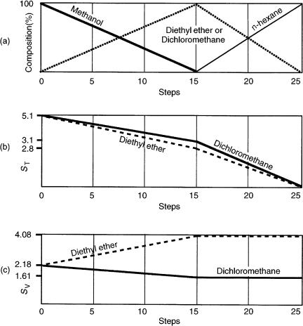
In the absence of a suitable method of optimization of the mobile phase for AMD (19), the procedure generally used is to start with 100% methanol (ST 5.1, SV 2.18) and to reduce its concentration in 15 stages, during which procedure the amount of solvent B (diethyl ether or dichloromethane) will increase from 0 to 100%. From the 15th to the 25th step, the concentration of solvent B is reduced and the concentration of n-hexane increased, until it reaches 100% (Figure 8.12(a)).
Figure 8.12(b) shows that if dichloromethane (ST 3.1, SV 1.61) or diethyl ether (ST 2.8, SV 4.08) are used, then the change in solvent strength is not very large. If, however, selectivity values are considered (Figure 8.12(c)) it is apparent that the selectivity value decreases when dichloromethane is used and increases when diethyl ether is used. It can be concluded that selectivity values must also be considered in the search for suitable solvents for nD.
8.8 MULTIPLE DEVELOPMENT IN TWO DIRECTIONS
Unfortunately, the fact that, in addition to the 2-D separation, a further increase in separation performance might be obtained by the use of multiple development
Multidimensional Planar Chromatography |
183 |
Figure 8.12 The ‘universal’ elution gradient during the stages of AMD separation: (a) change in mobile phase composition; (b) change of solvent strength; (c) change of selectivity value.
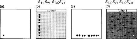
(20 – 22) for either or both orthogonal developments seems to have been rarely recognized. Figure 8.13(a) shows a sample applied to the chromatographic plate. After ‘n’ developments, during which the total solvent strength was reduced stepwise at constant selectivity (Figure 8.13(b)), the compounds were separated according to differences in polarity. In the second dimension, perpendicular to the first (Figure 8.13(c)), the chromatographic plate was redeveloped ‘m’ times such that the selectivity was changed at constant ST to achieve maximum spot capacity.
2-D TLC combined with multiple development is therefore a promising route which should lead to real improvements in planar chromatography in the near future.
184 |
Multidimensional Chromatography |
Figure 8.13 Schematic diagram of 2-D planar chromatographic separation using nD. In the first dimension (a and b) the total solvent strength was reduced stepwise at constant selectivity (ST1; SV1 : STn; SV1) to achieve differences in polarity. In the second dimension (c and d), the selectivity was changed at constant solvent strength (STn; SV1 : STn; SVm) to achieve maximum spot capacity.
8.9 MULTIPLE DEVELOPMENT IN THREE DIRECTIONS
A theoretical model whereby maximum peak capacity could be achieved by the use of 3-D planar chromatographic separation was proposed by Guiochon and coworkers (23 – 27). Unfortunately, until now, because of technical problems, this idea could not be realized in practice. Very recently, however, a special stationary phase, namely EmporeTM silica TLC sheets, has now become available for realization of 3-D PC. This stationary phase, developed as a new separation medium for planar chromatography, contains silica entrapped in an inert matrix of polytetrafluoroethylene (PTFE) microfibrils. It has been established that the separating power is only ca. 60% of that of conventional TLC (28); this has been attributed to the very slow solvent migration velocity resulting from capillary action.
The influence of external forces (overpressure or centrifugal force) on the structure of EmporeTM silica thin-layer sheets was demonstrated by Botz et al. (29) with the aid of scanning electron micrographs. These authors reported that the use of EmporeTM sheets for linear overpressured layer chromatography (OPLC) separations demands special preparation. The stretched sheets, placed on a sheet of glass or TeflonTM, must be impregnated with polymer suspension along all four of their edges. Afterwards, the inlet channel of the TeflonTM cover plate must be placed on the sheet for development in the first direction. After the first separation step, the chromatographic plate is dried and then developed in a perpendicular direction (the inlet channel of the TeflonTM cover plate must also be rotated through 90 º).
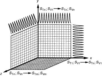
On completion of the 2-D OPLC separation, several layers of EmporeTM sheets, all with impregnated edges, can be carefully stacked on top of each other, with the developed 2-D sheet resting on the top. After the sheets have been pressed together (by application of hydraulic pressure, as normal) the 3-D OPLC separation can be started by introducing the mobile phase through an appropriate porous cover plate (which serves as the mobile phase inlet) (16). If the number of EmporeTM sheets is sufficient, a separation cube can theoretically be constructed (see Figure 8.14), thus enabling a spot capacity of n3, according to the number of boxes. After separation in
Multidimensional Planar Chromatography |
185 |
Figure 8.14 Schematic diagram of the peak capacity of a 3-D (n3) planar chromatographic system employing mobile phases of different composition; the number of cubes represents the number of compounds which can theoretically be separated.
the third dimension, the separated compounds would be found on different sheets. It might, however, also happen that the same spot could be found on more than one sheet. Needless to say, the limitations of such a system would clearly include all the disadvantages of 2-D TLC.
Botz et al. (29) also demonstrated, by scanning electron microscopy, that application of overpressure increases the density of the layer, which could be one reason for the higher separation efficiency. These results showed that EmporeTM silica TLC sheets enable extremely rapid separations (5–20 min) in one-dimensional OPLC, and gave good resolution. Theoretically, for a 3-D OPLC separations development times of 15 –60 min would be required. The separation cube of sheets could be especially useful for micropreparative separations (30).
Combination of 3-D OPLC with multiple development encompasses all of the advantages of three-dimensional and forced-flow planar chromatography, and the separating capacity of multiple development. Favourable conditions could be to start the separation in the first dimension, and then reducing the total solvent strength stepwise at constant mobile phase selectivity to achieve a crude separation on the basis of the polarity of the compounds to be separated. In the second (perpendicular) direction, multiple development could be performed at constant ST but with variation of the mobile phase selectivity. The third dimension would enable a combination of total solvent strength and mobile phase selectivity for improving the resolution of complex matrices (see Figure 8.14).
Theoretically, 3-D OPLC in combination with multiple development is the most powerful technique of instrumental planar chromatography. Unfortunately, suitable instrumentation is at an early stage of development.
186 |
Multidimensional Chromatography |
8.10 COUPLED LAYERS WITH STATIONARY PHASES OF DECREASING POLARITY
Chromatographic plates can be connected for both capillary-controlled and forcedflow planar chromatography (FFPC), i.e. irrespective of whether capillary action or forced-flow is the driving force for the separation. The first technique is denoted as ‘grafted’ planar chromatography (31), while the second is known as ‘long distance’ (LD) OPLC, which uses heterolayers (32, 33).
8.11 GRAFTED PLANAR CHROMATOGRAPHY
The idea of coupled TLC plates, denoted as graft TLC, was reported in 1979. Graft TLC (31) is a multiple system with layers of similar or different stationary phases for isolation of compounds from natural and/or synthetic mixtures on a preparative scale. Two plates are grafted together and clamped in the fashion of a lap-joint with the edges of their adsorbent layers in intimate contact, so that a compound from a chromatogram developed on the first chromatographic plate can be transferred to the second plate without the usual scraping of bands, extraction, and re-spotting. At that time, the method could be used for preparative purposes only – because home-made plates were employed, compounds could not be transferred quantitatively, as was necessary for analytical separations.
Nowadays, almost all commercially available HPLC stationary phases are also applicable to planar chromatography. In addition to the polar hydroxyl groups present on the surface of native silica, other polar functional groups attached to the silica skeleton can also enter into adsorptive interactions with suitable sample molecules (34). Silica with hydrophilic polar ligands, such as amino, cyano, and diol functions, attached to the silica skeleton by alkyl chains, all of which have been well proven in HPLC, have also been developed for TLC (34).
A simple method for serially connected TLC on coupled chromatographic plates coated with different stationary phases (6) is illustrated schematically in Figure 8.15. An appropriate amount of stationary phase A (light shading in Figure 8.15(a)) must be removed, as must a corresponding part of stationary phase B (dark shading in Figure 8.15(b)). The amounts removed are such that when the two chromatographic plates are turned face to face (Figure 15(c)) and are grafted (pressed) together (Figure 15(d)), the remaining regions of the layers overlap.
The configuration illustrated in Figure 8.15 is an ultra-micro chamber in which the vapour phase is practically unsaturated (35). The distance between the supporting glass plate and the stationary phase of the other chromatographic plate is the layer thickness, which depends on the type of analytical (20 –25 m) or preparative (0.5 – 2.0 m) plate applied. The sample to be separated (black zone in Figure 8.15(a)) is applied to stationary phase A after removal of the region of the layer not necessary for the graft TLC separation. The two plates must be clamped in lap-joint fashion with the edges of their stationary phases in close contact (Figure 8.15(d)) so that compounds from the chromatogram developed on the first chromatographic
Multidimensional Planar Chromatography |
187 |
Figure 8.15 Schematic diagrams of cross-sections of MD-TLC plates connected in series to ensure multidimensional separation on stationary phases of increasing polarity; hatched lines, glass plate; light shading, stationary phase A; dark shading, stationary phase B.
plate can be transferred to the second plate. This arrangement of the stationary phases can be regarded as multidimensional planar chromatography only if the second stationary phase (B) is much less polar than the first (A); otherwise, the second criterion of multidimensionality is not fulfilled.
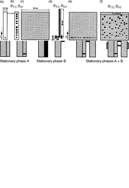
On the basis of the principle of grafted TLC, reversed-phase (RP) and normalphase (NP) stationary phases can also be coupled. The sample to be separated must be applied to the first (2.5 cm 20 cm) reversed-phase plate (Figure 8.16(a)). After development with the appropriate (ST1; SV1) mobile phase (Figure 8.16(b)), the first plate must be dried. The second (20 cm 20 cm) (silica gel) plate (Figure 8.16(c)) must be clamped to the first (reversed-phase) plate in such a way that by use of a strong solvent system (STx; SVx) the separated compounds can be transferred to the second plate (Figure 8.16(d)). Figure 8.16(e) illustrates the applied, re-concentrated
Figure 8.16 Views from above (a – c, e, and f) of coupled RP – NP chromatographic plates (without lines, RP stationary phase; light shading, NP stationary phase), and schematic diagram of a cross-section (d) through the clamped plates using a strong mobile phase (STx; SVx) for the transfer of the sample to be further separated.
188 |
Multidimensional Chromatography |
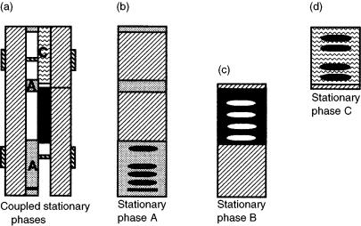
Figure 8.17 Schematic diagram of a cross-section (a) through the clamped plates, and views from above (b – d) of coupled plates serially connected to achieve multidimensional separation with stationary phases with different characteristics (hatched lines, glass plate; light shading, stationary phase A; dark shading, stationary phase B; wavy lines, stationary phase C).
samples, ready for development in the second direction. By use of a mobile phase of appropriate selectivity (ST2; SV2) an effective multidimensional planar chromatographic separation can be observed (Figure 8.16(f)).
Figure 8.17 depicts MD-PC performed on three different types of stationary phase (6). The three grafted chromatographic plates (Figure 8.17(a)) are clamped in lap-joint fashion with the edges of their stationary phases in close contact. The manner in which the three plates are prepared and the separation which can theoretically be achieved are also apparent from the schematic diagrams in Figures 8.17(b – d), in which the most polar stationary phase is phase ‘A’ and the least polar is stationary phase ‘C’.
8.12 SERIALLY CONNECTED MULTILAYER FORCED-FLOW PLANAR CHROMATOGRAPHY
Mincsovics and co-workers (36) found that OPLC is suitable for the development of several chromatographic plates simultaneously if the plates were specially prepared. With this multilayer technique many samples can be separated during a single chromatographic run. On the basis of this concept, Botz et al. (32, 33) proposed a novel OPLC technique with a significantly increased separation efficiency, in which the separation distance can be increased as a result of special arrangement of the chromatographic plates. This category of multilayer FFPC, linear development
Multidimensional Planar Chromatography |
189 |
(LD)-OPLC, involves the serial connection of the chromatographic plates. By application of this technique, it is also possible to use different stationary phases of decreasing polarity during a single development, as shown in Figure 8.18(a).
Specially prepared plates are necessary for this LD-OPLC technique in linear development mode (35) – all four edges of the chromatographic plates must be impregnated with a special polymer suspension. Movement of the mobile phase with a linear front can be ensured by placing a narrow plastic sheet on the layer. Three plates can be placed on top of each other to create the long development distance. The end of the first (top) chromatographic plate has a slit-like perforation to enable transfer of the mobile phase to the second layer, where migration continues until the opposite end of that layer. Development can then either continue to the next chromatographic plate or, if chromatography is complete, the mobile phase can be drained away. On this basis, 60 cm separation distances can be achieved with P-OPLC 50 equipment. As a consequence of the manner in which the layers are prepared, glass-backed plates can be used at the bottom of the stack only.
For this technique, the upper plate has a mobile phase inlet channel on one edge and a slit at the opposite edge for directing the mobile phase toward the next plate (33). The slit (width approx. 0.1 mm) can be produced by cutting the layers with a sharp blade; this enables easy passage of mobile phase and separated compounds without any mixing. The cushion of the OPLC instrument is applied to the uppermost layer only, and each plate presses on to the sorbent layer below.
The potential of serial connection of layers can be used for multidimensional planar chromatographic separations on different stationary phases of decreasing
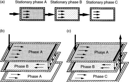
Figure 8.18 Schematic diagrams showing: (a) serially connected multilayer OPLC employing different types of stationary phase of decreasing polarity (A B C) as a type of MDFFPC; (b) fully off-line operational mode; (c) fully on-line operational mode.
190 |
Multidimensional Chromatography |
polarity. Fully off-line separation (Figure 8.18(b)), in which several samples are applied, is complete when the -front of the mobile phase reaches the end of the bottom plate. Figure 8.18(c) illustrates the fully on-line operating mode, in which all the compounds of the (single) sample to be separated have to be moved at the same separation distance. The mobile phase can therefore be directed from the lower plate in a manner similar to that in which it is introduced. This gives the possibility of on-line detection. For this fully on-line mode of operation, the length of all layers placed between the uppermost and lowest plates must be reduced by 1 cm, in order to ensure room for the mobile phase outlet.
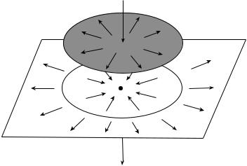
Figure 8.19 illustrates another example of the versatility of multidimensional OPLC, namely the use of different stationary phases and multiple development (nD) modes in combination with circular and ‘anticircular’ development and both off-line and on-line detection (37). Two different stationary phases are used in this configuration. The lower plate is square (e.g. 20 cm 20 cm), while the upper plate (grey in Figure 8.19) is circular with a diameter of, e.g. 10 cm. The sample must be applied on-line to the middle of the upper plate. In the OPLC chamber the plates are covered with a TeflonTM sheet and pressed together under an overpressure of 5 MPa. As the mobile phase transporting a particular compound reaches the edge of the first plate it must – because of the forced-flow technique – flow over to the second (lower) stationary phase, which is of lower polarity.
The place at which this transfer occurs is illustrated in Figure 8.19 as a thin circle on the lower chromatographic plate. Because the overpressure is uniform throughout the whole system, the compounds will be divided into two parts and migrate in both circular (outwards) and ‘anticircular’ (inwords) directions. A hole at the centre of the
Figure 8.19 Schematic diagram of the combination of multilayers (decreasing polarity) for OPLC with different types of development (circular and ‘anticircular’) and modes of detection (off-line and on-line).