

Multidimensional Chromatography
.pdf140 |
Multidimensional Chromatography |
Figure 6.4 Schematic diagram of an on-line SPE – SFE – GC system (from ref. 40):1, carbon dioxide; 2, high-pressure syringe pump; 3, gas chromatograph; 4, three-port valve; 5, oven; 6, extraction cell; 7, waste; 8, ten-port valve; 9 – 11 conditioning and washing solvents; 12, sample; 13, nitrogen.
of analytes trapped on to a SPE sorbent to a GC column. As CO2, the most widely used solvent for SFE, is a gas at room temperature, it therefore becomes the ideal solvent to quantitatively transport the analytes from the SPE cartridge to the GC column (5). Figure 6.4 shows a schematic drawing of a ‘home-made’ SPE – SFE – GC system (40).
The system is built by using three independent modules (SPE, SFE and GC) in such a way that it can be assembled to perform experiments in the on-line coupled mode (SPE – SFE, SFE – GC, SPE – GC and SPE – SFE – GC) or as independent units (GC, SPE, and SFE). This means that if we want to use the system for standard GC, there will be no problems, with the same applying for both SPE and SFE.
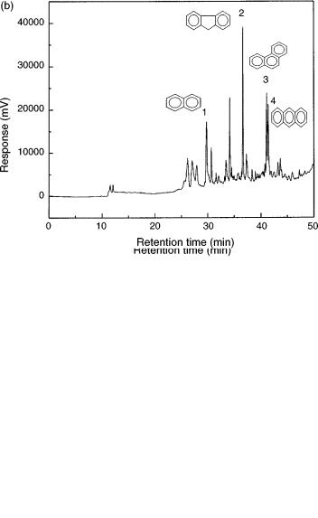
Operation of the SPE – SFE – GC system is very easy (see Figure 6.4). The SPE cartridge is conditioned (flasks 9 and 10) and washed (flask 11) depending upon the sorbent used. The first and second three-port valves (items 4) are then rotated to the SPE cartridge and waste positions, respectively. The sample contained in flask 12 is then loaded into the SPE cartridge (item 6) with the help of nitrogen (item 13). While the matrix and unwanted analytes goes to waste (item 7), the target compounds are trapped in the cartridge (item 6). After loading the sample into the extraction cell, the system is dried with nitrogen and the two valves are now switched to the SFE and GC feed positions, respectively, thus providing the transfer of the trapped analytes to the GC injector. A cryogenic system using liquid CO2 is used to trap the analytes in the first section of the capillary column. Details of the interface used for coupling the SFE module to the GC injector is shown in Figure 6.5 (40). Figure 6.6 (b) displays an SPE – SFE – HRGC photo ionization detector (PID) chromatogram of a water sample contaminated with several aromatic compounds.
Coupled Supercritical Fluid and Chromatographic Techniques |
141 |
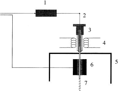
Figure 6.5 Schematic diagram of a typical interface used for on-line SFE – GC coupling (from ref. 40): 1, extraction cell; 2, restrictor; 3, on-column injector; 4, heater; 5, oven; 6, cryogenic module; 7, column.
6.5SFE – SFC
The on-line coupling of supercritical fluid extraction with Supercritical Fluid Chromatography (SFE – SFC) is easier to achieve than those involving other chromatographic techniques. This is particularly the case when using neat CO2 in both systems since it does not requires changes in the fluid composition or physical state. The SF extracts will contain the extracted analytes in CO2 and these can be directly transported into the SFC system, which also uses CO2 as the mobile phase. Different approaches have been used to trap and focus the analytes into the SFC column (26, 27), including a dual-trapping system to eliminate the modifier solvent (41).
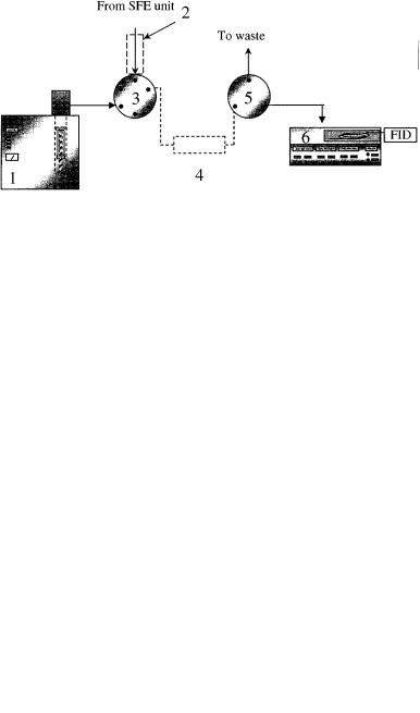
Figure 6.7 shows a schematic diagram of an on – line SFE – SFC coupled system (42), with details of the interface being shown in Figure 6.8 (42).
6.6SFE-LC
Unfortunately, not much experimental work has been carried out on the combination of supercritical fluid extraction and liquid chromatography systems (43, 44). One of the reasons for this arises from the difficulties in achieving compatibility between the extraction solvent and the LC mobile phase. Baseline perturbations have been
142 |
Multidimensional Chromatography |
Figure 6.6 SPE – SFE – HRGC(PID) chromatograms obtained for (a) a mixture of analytical standards of selected aromatic compounds in water, and (b) the analysis of a water sample contaminated with various aromatic compounds.
Coupled Supercritical Fluid and Chromatographic Techniques |
143 |
Figure 6.7 Schematic diagram of an on-line SFE – SFC system (from ref. 42):1, carbon dioxide; 2, pump; 3, oven; 4, extraction cell; 5, interface; 6, SFC unit.
observed with UV detection, attributed to the solubility of the CO2 in the aqueous mobile phase, particularly at low flow rates (28).
6.7 ON-LINE COUPLING OF SUPERCRITICAL FLUID EXTRACTION WITH CAPILLARY ELECTRODRIVEN SEPARATION TECHNIQUES (SFE – CESTs)
Electrodriven Separation Techniques encompass a wide range of analytical procedures based on several distinct physical and chemical principles, usually acting together to perform the required separation. Example of electrophoretic-based techniques includes capillary zone electrophoresis (CZE), capillary isotachophoresis (CITP), and capillary gel electrophoresis (CGE) (45 – 47). Some other electrodriven separation techniques are based not only on electrophoretic principles but rather on chromatographic principles as well. Examples of the latter are micellar
Figure 6.8 Schematic diagram of a typical interface used for on-line SFE – SFC coupling (from ref. 42):1, pump; 2, heated transfer line; 3, valve; 4, sample concentrator; 5, valve; 6, SFC unit.
144 |
Multidimensional Chromatography |
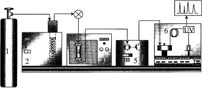
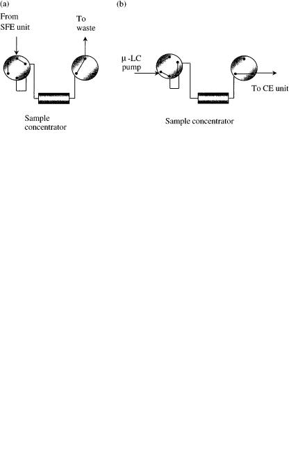
electrokinetic chromatography (MEKC) and, more recently, capillary electrochromatography (CEC) (48 – 52). All capillary electrodriven separation techniques (CESTs) suffer from the same problem, i.e. the low detection sensitivity due to the use of narrow capillaries which are required in order to achieve the desired efficiency and prevent an excess of heating due to the Joule effect (53, 54). One way to overcome this limitation has been the use of membranes, cartridges, hollow fibers and similar approaches to concentrate the analytes prior to the electrophoretic separation (55 – 57). A more general approach that can overcome this problem, as well as to provide additional features, particularly for the analysis of complex real samples, involves the on-line coupling of supercritical fluid extraction and capillary electrodriven separation techniques (SFE – CESTs) (58 – 60). Figure 6.9 displays a schematic diagram of an on-line coupled SFE – CEST system (58). The developed system consists of three basic and independent parts, namely the SFE system, an interface to couple the two systems together and the capillary electrodriven apparatus. The sample is extracted in the SFE unit and is then directed to the interface in order to compatibilize the SFE conditions with those required by the electrodriven separation system. The interface developed for this instrument is displayed in Figure 6.10. By using this interface, the SFE – CEST system can be used for extraction, clean-up, sample concentration – enrichment and analysis all in just one step (58). The operational procedure is quite straightforward. Two different operational modes have been investigated with the developed interface, i.e. the concentration mode and the direct mode (see figures 6.11 and 6.12).
The concentration mode is used when the extract from the SFE module is not concentrated enough to be directly analyzed by the CE instrument, and thus requires a concentration step, which is carried out in the concentrator device. In this mode, during the concentration step the extract from the SFE cell enters the first valve (positioned in the concentration mode (Figure 6.11(a)), and is then directed to and adsorbed into the sample concentrator which contains an SPE cartridge. While the
Figure 6.9 Schematic diagram of an on-line SFE – CEST system (from ref. 58):1, CO2 cylinder; 2, syringe pump; 3, oven; 4, extraction cell; 5, interface; 6, CE instrument.
Coupled Supercritical Fluid and Chromatographic Techniques |
145 |
Figure 6.10 Schematic diagram of a typical interface used for on-line SFE – CEST coupling (from ref. 57): 1, micro-LC pump; 2, heated restrictor; 3, six-port valve; 4, sample concentrator; 5, three-port valve; 6, CE instrument.
analytes of interest are concentrated in the cartridge, the solvent is vented through the valve (item (5) in Figure 6.10). Upon completing the concentration step, the valves are then switched to the elution position (Figure 6.11(b), and a pump delivers the appropriate solvent to elute the sample from the SPE cartridge to the CE vial. After this step, the CE analysis is then carried out.
The direct mode is used when the concentration of the SFE extract is enough for direct analysis in the CE instrument without the need for a pre-concentration step. In this case, the sample concentrator is by-passed and the SFE extract goes directly to the CE instrument. The extract is collected in a CE vial containing an appropriate solvent and is thus ready for the CE analysis (Figure 6.12).
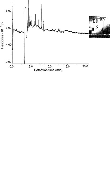
A practical application of SFE – CEST coupling is shown in Figure 6.13, which displays the electropherogram obtained for a tomato sample contaminated with a pesticide, i.e. carbaryl. The sample was placed in the SFE cell, extracted with CO2
Figure 6.11 Schematic diagrams of the valve configurations for the SFE – CEST coupling in the concentration mode, shown for (a) the concentration step and (b) the elution step. (from ref. 58)
146 |
Multidimensional Chromatography |
Figure 6.12 Schematic diagram of the interface used for direct SFE – CEST coupling without a sample pre-concentration step: 1, micro-LC pump; 2, heated restrictor; 3, six-port valve; 4, direct by-pass to the CE unit; 5, three-port valve; 6, CE instrument. (from ref. 58).
and the extract then concentrated in the concentrator device, while the solvent from the SFE step was led to waste. The concentrated extract was then desorbed from the concentrator to the CE unit where analysis was performed in the micellar electrokinetic chromatography (MEKC) mode. Therefore, this particular application describes the use of an on-line SFE – MEKC coupling system. Further details concerning this and other applications using such a system can be found elsewhere (58 – 60).
Figure 6.13 SFE – MEKC electropherogram of the pesticide carbaryl in a tomato sample; the peak assigned number (4) corresponds to the migration time of carbaryl. (from ref. 58).
Coupled Supercritical Fluid and Chromatographic Techniques |
147 |
6.8 FROM MULTIDIMENSIONAL TO UNIFIED CHROMATOGRAPHY PASSING THROUGH SUPERCRITICAL FLUIDS
In 1965, Giddings proposed that there are no theoretical boundaries between GC, LC and SFC, and that such distinctions are arbitrary, artificial and counter-productive (61). This concept was extended by Ishii et al. who proposed the concept of Unified Chromatography in 1988 (62). According to these authors, it is possible to demonstrate different-mode separations, i.e. liquid chromatography (LC), supercritical fluid chromatography (SFC) and gas chromatography (GC) by using a single chromatographic system (62). Still according to Ishii and co-workers, the separation mode could be selected by changing the pressure in the column and the column temperature (62). Since then a selected number of papers have appeared in the literature covering this subject (for a review of Unified Chromatography, the interested reader should consult references 63 – 65). Most of the work carried out so far is in fact related to multidimensional chromatography using different chromatographic modes, and not on Unified Chromatography as originally described by Ishii and coworkers. In this respect, several reports have dealt with techniques such as GC – GC, LC – LC, LC – GC, SFC – GC, and so on. Using such an approach, either the total or a fraction of the analytes exiting the first column is transferred (switched) to a second column for a second ‘dimension’ of analysis. The major conceptual difference between this approach and the Unified Chromatography concept is that in the latter system the sample is introduced into the first analytical unit (e.g GC) and part of it is then eluted from the column by using a ‘proper’ mobile phase. Following this and without changing the column, the other portion of the sample which is still retained on this column is then eluted in a different chromatographic mode (e.g. SFC), either with or without changing the mobile phase. Since both approaches, i.e. Multidimensional Chromatography and Unified Chromatography, use equivalent symbols to express the hyphenated character of both (e.g. GC – SFC), there is often confusion about their fundamental principles. In short, Multidimensional Chromatography uses a column-switching approach, with the analyte being transferred from one to the other column, while Unified Chromatography uses the same column for all of the chromatographic modes, without any analyte transfer. Since in both cases the techniques are coupled on-line they are both considered to be hyphenated systems. Supercritical fluid chromatography plays a very important role in the Unified Chromatography approach. Most of the (albeit, rather few) papers published on Unified Chromatography use SFC as a ‘bridge’ between the two limiting extremes of the mobile phase, represented by a gas (in GC) and a liquid (in LC). This subject will not be covered any further here since it is discussed in detail elsewhere in this present volume (see Chapter 7).
REFERENCES
1.C. Cagniard de la Tour, Ann. Chim. Phys. 21: 27 (1822).
2.J. B. Hannay and J. Hogarth, On the solubility of solids in gases’, Proc. R. Soc. (London) 29: 324 – 326 (1879).
148 |
Multidimensional Chromatography |
3.J. B. Hannay and J. Hogarth, ‘Proc. R. Soc. (London)’, 30: 178 (1880).
4.E. H. Buchner, Z. Phys. Chem., 54: 665 (1906).
5.T. L. Chester, J. D. Pinkston and D. E. Raynie, ‘Supercritical fluid chromatography and extraction’, Anal. Chem. 70: 301R – 319R (1998).
6.L. T. Taylor Introduction to Supercritical Fluid Extraction, Research and Development Magazine Publishers, USA (1995).
7.R. E. Majors, ‘An overview of sample preparation’, LC – GC 9: 16 – 18 (1991).
8.S. S. H. Rizvi and A. L. Benado, ‘Supercritical propane systems for separation of continuous oil mixtures’, Ind. Eng. Chem. Res. 26: 731 – 737 (1987).
9.R. E. Wilson, P. C. Keith and R. E. Haylett, ‘Liquid propane. Use in dewaxing, deasphalting and refining heavy oils’, Ind. Eng. Chem. 28: 1065 –1078 (1936).
10.N. L. Dickerson, J. M. Meyers, J. Am. Oil Chem. Soc. 29: 235 – 239 (1952).
11.F. M. Lanças and S. R. Rissato, ‘Influence of temperature, pressure, modifier and collec-
tion mode on supercritical CO2 extraction efficiencies of diuron from sugar cane and orange samples’, J. Microcolumn Sep. 10: 473 – 478 (1998).
12.S. R. Sargenti and F. M. Lanças, ‘Influence of the extraction mode and temperature in the supercritical fluid extraction of Tangor murcote (Blanco) for Citrus sinensis (Osbeck)’,
J.Microcolumn Sep. 10: 213 – 223 (1998).
13.F. M. Lanças, S. R. Rissato and M. S. Galhiane, ‘Off-line SFE – MEKC determination of diuron in sugar cane and orange samples’, J. High Resolut. Chromatogr. 21: 519 – 522 (1998).
14.M. C. H. Tavares, J. H. Vilegas and F. M. Lanças, ‘Capillary supercritical fluid chromatography (c-SFC) analysis of underivatized triterpenic acids’, Phytochem. Anal. 12: 134 –137 (2001).
15.M. C. H. Tavares, ‘Project, construction and applications of a new capillary supercritical fluid chromatography’, Ph. D. Thesis, University of São Paulo, Brazil. (1999)
16.K. Hartonen and M.-L. Riekkola, ‘Detection of -blockers in urine by solid-phase extraction – supercritical fluid extraction and gas chromatography – mass spectrometry’,
J.Chromatogr. 676: 45 – 52 (1996).
17.L. T. Taylor, Supercritical Fluid Extraction, John Wiley & Sons, New York (1996).
18.S. A. Westwood (Ed.), Supercritical Fluid Extraction and its Use in Chromatographic Sample Preparation, CRC Press, Boca Raton, FL (1992).
19.K. Jinno (Ed.), Hyphenated Techniques in Supercritical Fluid Chromatography and Extraction, Elsevier, Amsterdam (1992).
20.B. Wenclawiak (Ed.), Analysis with Supercritical Fluids: Extraction and Chromatography, Springer-Verlag, Berlin (1992).
21.M. L. Lee and K. E. Markides, Analytical Supercritical Fluid Chromatography and Extraction, ‘Chromatography Conferences’, Provo, USA (1990).
22.T. Hirschfeld, ‘Hyphenated methods’, Anal. Chem. 52: 297A – 312A (1980).
23.I. L. Davies, M. W. Raynor, J. P. Kithinji, K. D. Bartle, P. T. Williams and G. E.
Andrews, ‘LC – GC, SFC – GC and SFE – GC interfacing’, Anal. Chem. 60: 683A – 702A(1988).
24.M. D. Burford, K. D. Bartle and S. B. Hawthorne, ‘Directly coupled (on-line) SFE – GC: instrumentation and applications’, Adv. Chromatogr. 37: 163 – 204 (1997).
25.P. Sandra, A. Kot, A. Medvedovici and F. David, ‘Selected applications of the use of supercritical fluids in coupled systems’, J. Chromatogr. 703: 467 – 478 (1995).
26.H. Daimon and Y. Hirata, ‘Trapping efficiency and solute focusing in on-line supercritical fluid extraction/capillary supercritical fluid chromatography’, J. Microcolumn Sep. 5: 531 – 535 (1993).
Coupled Supercritical Fluid and Chromatographic Techniques |
149 |
27.H. Daimon and Y. Hirata, ‘Direct coupling of capillary supercritical fluid chromatography with supercritical fluid extraction using modified carbon dioxide’, J. High Resolut. Chromatogr. 17: 809 – 813 (1994).
28.M. Ashraf-Khorassani, M. Barzegar and Y. Yamini, ‘On-line coupling of supercritical fluid extraction with high performance liquid chromatography’, J. High Resolut. Chromatogr. 18: 472 – 476 (1995).
29.D. C. Tilotta, D. L. Heglund and S. B. Hawthorne, ‘Online SFE – FTIR spectrometry with a fiber optic transmission cell’, Am. Lab. 28: 36R – 36T (1995).
30.T. Greibrokk, ‘Applications of supercritical fluid extraction in multidimensional systems’, J. Chromatogr. 703: 523 – 536 (1995).
31.R. Fuoco, A. Ceccarini, M. Onor and S. Lottici, ‘Supercritical fluid extraction combined online with cold-trap gas chromatography/mass spectrometry’, Anal. Chim. Acta 346: 81 – 86 (1997).
32.J. T. B. Strode and L. T. Taylor, ‘Supercritical fluid extraction employing a variable
restrictor coupled to gas chromatography via a sample pre-concentration trap’,
J.High Resolut. Chromatogr. 19: 651 – 654 (1996).
33.X. Lou, H.-G. Janssen and C. A. Cramers, ‘Investigation of parameters affecting the online combination of supercritical fluid extraction with capillary gas chromatography’, J. Chromatogr. 750: 215 – 226 (1996).
34.E. S. Francis, M. Wu, P. B. Farnsworth and M. L. Lee, ‘Supercritical fluid extraction/gas chromatography with thermal desorption modulator interface and nitro-specific detection for the analysis of explosives’, J. Microcolumn Sep. 7: 23 – 28 (1995).
35.P. B. Farnsworth, M. Wu, M. Tacquard and M. L. Lee, ‘Background correction device for enhanced element-selective gas chromatographic detection by atomic emission spectroscopy’, Appl. Spectr. 48: 742 – 746 (1994).
36.D. R. Gere, C. R. Knipe, P. Castelli, J. Hedrick, Randall Frank, L. G., H. SchulenbergSchell, R. Schuster, L. Doherty, J. Orolin and H. B. Lee, ‘Bridging the automation gap between sample preparation and analysis: an overview of SFE, GC, GC –MS and HPLC applied to environmental samples’, J. Chromatogr. Sci. 31: 246 – 258 (1993).
37.E. Anklam, H. Berg, L. Mathiasson, M. Sharman and F. Ulberth, ‘Supercritical fluid extraction (SFE) in food analysis: a review’, Food Additive Contam. 15: 729 – 750 (1998).
38.V. Janda, M. Mikesˇová and J. Vejrosta, ‘Direct supercritical fluid extraction of waterbased matrices’, J. Chromatogr. 733: 35 – 40 (1996).
39.E. M. Thurman and M. S. Mills, Solid-Phase Extraction: Principles and Practice, John Wiley & Sons, New York (1998).
40.J. S. S. Pinto, E. Cappelaro and F. M. Lanças, ‘Design and construction of an on-line SPE – SFE – HRGC system’, J. Braz. Chem. Soc. 12: 192 –195 (2001).
41.U. Ullsten and K. E. Markides, ‘Automated on-line solid phase adsorption/supercritical fluid extraction/supercritical fluid chromatography of analytes from polar solvents’,
J.Microcolumn Sep. 6: 385 – 393 (1994).
42.M. C. Tavares and F. M. Lanças, “On-line coupling of supercritical fluid extraction with supercritical fluid chromatography”, J. Braz. Chem. Soc. in press (2001).
43.C. Mougin and J. Dubroca, ‘On-line supercritical fluid extraction and high performance
liquid chromatography for determination of triazine compounds in soil,
J. High Resolut. Chromatogr 19: 700 – 702 (1996).
44.M. H. Liu, S. Kapila, K. S. Nam and A. A. Elseewi, ‘Tandem supercritical fluid extraction and liquid chromatography system for determination of chlorinated phenols in solid matrices’, J. Chromatogr. 639: 151 – 157 (1993).
45.H. Engelhardt, W. Beck and T. Schmitt, Capillary Electrophoresis: Methods and Potentials, Vieweg, Wiesbaden, Germany (1996).