

Multidimensional Chromatography
.pdf120 |
Multidimensional Chromatography |
Figure 5.2 Schematic representation of the final column-switching system: (a) forwardflush position; (b) back-flush position (further details are given in the text). Reprinted from Journal of Chromatography, A 828, A. K. Sakhi et al. ‘Quantitative determination of endogenous retinoids in mouse embryos by high-performance liquid chromatography with on-line solid-phase extraction, column switching and electrochemical detection’, pp. 451 – 460, copyright 1998, with permission from Elsevier Science.
strongly hepatotoxic cyclic heptapeptides produced by some species of freshwater cyanobacteria (blue – green algae) (28). These microcystins represent a health risk to humans through drinking water, since they have been found to act as tumor promoters (29). Several chromatographic analytical procedures for microcystins have been
Coupled-Column Liquid Chromatography |
121 |
suggested and reversed-phase HPLC is frequently the technique of choice for these types of analyses (30). However, considering that these compounds may be present at low levels in natural and drinking water ( 1 g/l), a preconcentration step before one-dimensional HPLC analysis is usually required (31 – 33). Furthermore, the proteins present in samples containing cyanobacteria are particularly troublesome since they tend to denature on reversed-phase packing and render the column useless (distorted peak shape, multiple peaks, etc.) (34). In the proposed LC – LC system, a precolumn consisting of a Zorbax CN cartridge was used for simultaneous enrichment and clean-up of the microcystins in water. The sample (100 ml) was passed through the cartridge on the enrichment side at a flow rate of 3 ml/min, and the microcystins were strongly retained in a narrow band on the top of the cartridge, due to their high hydrophobicity. At the same time, the analytical column was equilibrated with the starting mobile phase consisting of 10 mM phosphate buffer (pH, 2.5), containing 25% (vol/vol) acetonitrile. Desorption was performed by coupling the cartridge online with the analytical column and starting the gradient. Gradient elution was performed in the opposite direction to the sample preconcentration as follows: 0% of B at 0 min, 20% of B at 38 min, 60% of B at 42 min, and then isocratic under the same conditions until a period of 50 min. In this system, the mobile phase B was acetonitrile and the elution was carried out at a flow rate of 1 ml/min. Microcystins are peptides of differing hydrophobicity that can be readily chromatographed by using reversed-phase (RP)-HPLC. An example of the determination of microcystins (-LR, -RR and -YR) from a water sample by using the developed procedures is reported in Figure 5.3. Considering the two examples reported above regarding sample enrichment, the most important parameter is the sensitivity of the method (or minimal detectable concentration of analytes), determined by the sensitivity of the detector used, the adsorption capacity of the precolumn, the sample volume, the desorption and the chromatographic procedures. Two distinct processes are involved, i.e. (i) a frontal chromatography during the enrichment step, and (ii) a displacement chromatography during the desorption step.
A fundamental parameter characterizing the usefulness of a given precolumn for enrichment purposes is the breakthrough volume, VB. This volume can be determined by monitoring continuously or discretely the detector signal at the outlet of the precolumn (35 – 37). The breakthrough volume can be defined by the following expression (37):
VB VR 2.3 V |
(5.21) |
where V is the standard deviation depending on the axial dispersion of analyte along the bed of particles in the precolumn. If the capacity factor, kS of the analyte eluted with a mobile phase that corresponds to the sample solvent, wash solvent or elution solvent can be predicted and if V0, the dead volume of the precolumn, is determined, then VR can be calculated by using the following expression:
VR V0(1 k S) |
(5.22) |
while if the number of theoretical plates, N, of the precolumn is known, V can be
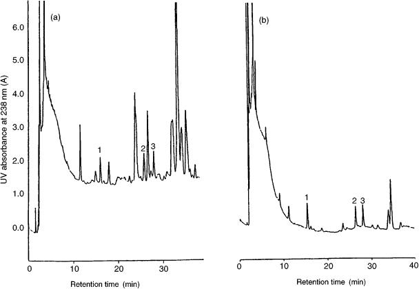
Figure 5.3 Analysis of 100 ml of (a) surface water and (b) drinking water sample spiked with 0.1 g/ml of microcystins, using column-switching HPLC: 1, microcystin-RR; 2, microcystin-YR; 3, microcystin-LR. Reprinted from Journal of Chromatography A, 848, H. S. Lee et al., ‘On-line trace enrichment for the simultaneous determination of microcystins in aqueous samples using high performance liquid chromatography with diode-array detection’, pp 179 – 184, copyright 1999, with permission from Elsevier Science.
122
Chromatography Multidimensional
Coupled-Column Liquid Chromatography |
|
123 |
|||||
calculated from the following: |
|
|
|
|
|
|
|
|
|
V0 |
(1 |
k ) |
(5.23) |
||
|
|
|
|||||
|
|
|
|||||
v |
|
√N |
S |
|
|||
|
|
|
|
|
|
||
By combining equations (5.22) and (5.23), equation (5.21) can be rewritten as follows:
VB (1 k S) 1 2.3 √ |
|
V0 |
(5.24) |
N |
However, for very highly retained solutes direct measurement of the capacity factor kS is not possible, and this parameter must be predicted on the basis of retention data determined with a stronger mobile phase. The determination of VB is an essential step in the optimization of trace enrichment and clean-up procedures.
Loading of the analytes on the analytical column can be carried out either in the back-flush or forward-flush modes. The back-flush mode allows a better resharpening of the solute band than the forward-flush mode. However, such a flow reversal may lead to precolumn packing disturbances. In addition, back-flushing does not protect the analytical column as well as forward-flushing (10). In fact, other than analytes, a large number of contaminants can be simultaneously sorbed on, and then eluted from the precolumn. In the development of a new LC – LC enrichment method, we have to deal with the following: (i) the elaboration of a carefully designed gradient profile to achieve a more or less stepwise elution of the retained components from the precolumn; (ii) the choice of a more selective stationary phase for the trace-enrichment step; (iii) the use of a selective detection principle.
An LC – LC separation system may be used in either the profiling or targed mode (11). The purpose in the profiling mode is to separate all single components from a complex mixture. Every component from the first column (primary column) is fractionated and transferred in the second column (secondary column). In contrast, the purpose of LC – LC separation in the targeted mode is to isolate either a single or a few components of similar retention in a complex mixture containing components having a wide range of capacity factor values. Targeted component analysis is carried out by transferring a wide or narrow cut of the chromatographic effluent from the primary column to the secondary column by flow switching and the mobile phase is thereby diverted or reversed. The fraction of interest to be transferred on to the secondary column may be early-eluting analytes (first eluted zone, usually the named the ‘front-cut’), or components eluted in the middle of the chromatographic effluent (‘heart-cut’) or at the end of the chromatogram (‘end-cut’) (38).
A schematic diagram of a ‘heart-cut’ LC – LC system is depicted in Figure 5.4. The column switching technique was developed by employing two high-pressure four-way pneumatic valves inserted before and after the precolumn (39). The ‘frontcut’ and the ‘end-cut’ of the sample eluted from the first column were vented to waste. The valves were manipulated to transfer only the ‘heart-cut’ of the analyte of interest to the analytical column. The detailed operational conditions for the fourstep sequence of this system can be described as follows:
(Step 1) Divert initial portion of chromatogram to waste. The sample is injected with the valve A (left) closed; mobile phase flows through the precolumn to valve B (right), which is opened to waste.

124 |
Multidimensional Chromatography |
Figure 5.4 Schematic diagrams of a heart-cut valve configuration system. Reprinted from Journal of Chromatography, 602, S. R. Villaseñor, ‘Matrix elimination in ion chromatography by ‘heart-cut’ column switching techniques’, pp. 155 – 161, copyright 1992, with permission from Elsevier Science.
Coupled-Column Liquid Chromatography |
125 |
(Step 2) Introduce heart-cut to the analytical column and detector. At the predetermined time interval, which was previously calculated by eluting analyte standards without the analytical column, i.e. the onset of the heart-cut, valve B is closed to divert the precolumn effluent to the analytical column.
(Step 3) Bypass the precolumn and detection of the analyte of interest. When all of the analytes of interest have been eluted from the precolumn, valve A is opened so that the eluent stream is diverted to valve B, which is immediately opened to allow eluent from valve A to flow into the analytical column, thus bypassing the precolumn.
(Step 4) Precolumn clean-up not shown in Figure 5.4. After the heart-cut analytes have been transferred to the analytical column, a step-gradient programme is used to flush the precolumn of the more strongly retained compounds. An additional pump configuration makes precolumn clean-up possible while the analysis is running.
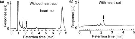
The LC – LC configuration has been applied to sulfide analysis in a variety of different matrices, as well as for acetate and trifluoroacetate analysis in peptides (as shown in Figure 5.5).
A critical operation in target component analysis by LC – LC is the selection and transference of the eluent fraction from the primary to the secondary column. In complex samples, it is inevitable that a part of the interfering components will be transferred together with the analytes of interest. Selection is usually achieved by time-based valve switching, assuming that the analytes’ retention times and peak widths are constant. This involves careful advance planning of the chromatographic conditions and imposes a standard of excellent retention time reproducibility for the analytes. Major drawbacks of the above method are that column ageing will change the retention time of the analyte, while peak width will increase due to column degradation. Under these conditions, the analyte will move either partially or totally out of the preselected time window for valve switching and quantitation will be compromised in the analytical column (12). Determination of the heart-cut timing parameters can be automated through repeated analysis with various retention-time windows of a sample containing a large amount of the analyte or a sample that has been spiked with the compound of interest (40).
Figure 5.5 Trifluoroacetate determination in calcitonin acetate (a) without and (b) with heart-cut column switching. Reprinted from Journal of Chromatography, 602, S. R. Villaseñor, ‘Matrix elimination in ion chromatography by ‘heart-cut’ column switching techniques’, pp 155 – 161, copyright 1992, with permission from Elsevier Science.
126 |
Multidimensional Chromatography |
As enunciated above, a high-resolving LC – LC system can be implemented by employing columns that operate by using a different separation mechanism (heteromodal LC – LC). Several combinations of mechanisms with great dissimilarity are conceivable. These include the following: size exclusion –ion exchange; size exclusion –reversed phase; ion exchange –reversed phase; reversed phase (alkyl ligand ) –reversed phase (ion-pairing eluent); reversed phase (alkyl ligand ) –reversed phase (electron-pair acceptor or donator ligand); reversed phase –affinity (biospecific interactions); normal phase (plain silica ) –normal phase (electron-pair acceptor or donator ligand (41). In addition, a significant number of applications describing the coupling of immunoaffinity chromatography and reversed-phase HPLC have been reported over the last ten years. A specific antibody is immobilized on a appropriate sorbent to form a so-called immunosorbent (IS) for packing into a HPLC precolumn. The antibodies are selected in order to involve antigen – antibody interactions, thus providing selective extraction methods based on molecular recognition. Samples or extracts from biological matrices are introduced on to this immunoaffinity system with little or no sample pretreatment. The analytes are then eluted from the immunoaffinity column and analysed directly by suitable on-line HPLC methods. Immunoaffinity columns can be packed with chemically activated sepharose beads, and antibodies will then covalently bind to these beads (42). However, Sepharosebased immunosorbents are not pressure resistant and therefore direct connection of the precolumn to the analytical column could not be achieved. When using these immunosorbents, analytes are usually desorbed at low pressure in a second precolumn packed with C18, which subsequently can be coupled on-line to the LC system (43 – 45). Antibodies have also been immobilized on silica-based sorbents. The particular advantage of silica is its pressure resistance, which means that it can be used directly in on-line LC – LC systems (46 – 48). The on-line set-up using a silica-based immunosorbent precolumn is very simple and does not differ to any great extent from that which uses a single reversed-phase precolumn. Heteromodal LC – LC coupling has also been widely employed as a chiral separation technique, which usually involves sequential chromatography on a chiral and an achiral column. The consecutive order in which the columns are combined can be varied (e.g. first a chiral column, then an achiral column or vice versa), depending on the problem to be solved and the main restrictions involved. Such restrictions may be a low sample amount, a low analyte concentration or a complex sample matrix, as well as a high degree of optical purity to be monitored (49 – 53). Enantiomeric separations can also be easily achieved by a two-dimensional HPLC system using achiral columns in both dimensions (54). Separation of unmodified amino acids in complex mixtures was achieved by employing two different separation methods. First, the amino acid separation was carried out by means of a cation-exchange column by elution with a lithium chloride – lithium citrate buffer, and then each peak corresponding to an individual amino acid was switched to an achiral reversed-phase column where the chiral discrimination was achieved by using a mobile phase containing a chiral copper (II) complex.
LC – LC coupling systems are also employed to perform separations requiring very large plate numbers. However, it has been demonstrated (see equation (5.20) that for coupled columns peak capacity increases linearly with the square root of n

Coupled-Column Liquid Chromatography |
127 |
(number of columns connected in series), although the column pressure drop increases linearly with the length. In practice, the operating conditions essentially limit the number of columns that may be coupled together and therefore restricts the total number of theoretical plates that can be generated in a reasonable time. An alternative way to improve the number of theoretical plates is the use of the same column in a recycling chromatographic system (55). This technique consists of a switching-column method which is accomplished by adding a switching valve to the fluid system to permit the eluent, or some designed portion thereof, to be directed from the column outlet back into the column inlet. The process can then be repeated, with each subsequent pass resulting in an increase of the separation between the peaks. In practice, recycling increases the effective length of the column by returning the eluted analyte to the head of the column for further separation. A schematic representation of a conventional chromatographic recycling system is depicted in Figure 5.6. The recycling technique offers, with respect to coupled columns, the possibility to increase the resolution by a large number of theoretical plates obtained by increasing the number of sample passes through the HPLC column and maintaining the column length and pressure constant. There are two limiting factors in recycling chromatographic methods, as follows: (i) the phenomenon of remixing of the separated analytes, which occurs when the fastest moving peak of the sample overtakes the slowest moving components after a certain number of cycles; (ii) the extracolumn band broading occurring in the pump, valve devices, connecting tubes, and detector at each cycle in the detector-to-injection transfer. The influence of column and extra-column effects on the maximum efficiency realizable in recycling
Figure 5.6 Schematic design for recycling chromatography in which the effluent is recycled through the pump: 1, eluent; 2, pump; 3, injector; 4, chromatographic column; 5, detector; 6, three way valve; 7, waste; 8, T-connection.
128 |
Multidimensional Chromatography |
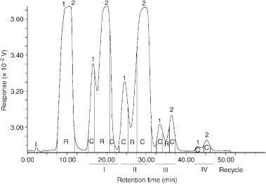
chromatography has been treated theoretically and mathematical models have been developed for the description of specific recycling techniques (56 – 60). Recycling is a chromatographic technique mainly used in preparative LC to increase the effective separation power (selectivity and efficiency), while avoiding the expense of purchasing and operating longer columns and additional column sections. The preparative recycling system can be improved by peak shaving (61). In this method, the recycling valve is used during each cycle and switched to direct unwanted components to waste, to collect portions of pure components of interest from peak fronts and tails, and to recycle the remainder of incompletely separated sample mixtures back through the column. An example of the advantages of a recycle chromatographic method with peak shaving to separate closely related compounds with an value near to 1 is shown in Figure 5.7. In this figure, two polymethoxyflavones were separated to obtain pure compounds which were used as HPLC standards to construct calibration graphs, employing cumarin as the internal standard, for their quantitative evaluation in sweet orange and mandarin essential oils (62). Polymethoxyflavones were isolated by a recycling system combined with peak shaving, having a configuration similar to that shown in Figure 5.6. With the HPLC previously in the recycle mode, the essential oils were fractionated on a glass column (300 60 mm id.) filled with silica gel, using light petroleum/ethyl acetate (80:20 vol/vol) as the mobile phase at a flow rate of 1.0 ml/min (62). As illustrated in Figure 5.7, in order to
Figure 5.7 Separation of tangeretin and heptamethoxyflavon by recycle HPLC: R, recycle; C, collected; 1, tangeretin; 2, heptamethoxyflavon. Reprinted from Essenze Derivati Agrumari, 63, L. Mondello et al., ‘Isolamento di polimetossiflavoni dagli olii essenziali di arancia dolce e di mandarino mediante cromatografia su colonna e HPLC semipreparativa con riciclo’, pp. 395 – 406, 1993, with permission from Essenze Derivati Agrumari.
Coupled-Column Liquid Chromatography |
129 |
isolate tangeretin and heptamethoxyflavon, a large quantity of tangeretin was collected from the peak front and tail on the first pass. As the heavy sample load was reduced on each successive pass by shaving, the column’s effective separation efficiency increased, thus reducing the number of passes necessary to separate and recover the two compounds, which were completely separated and collected by employing only four recycles. Under the same conditions, other oxygen heterocyclic compounds of citrus essential oils were isolated (63) and used to prepare a library of mass spectra to identify these compounds in samples of genuine cold-pressed citrus oils by HPLC hyphenated techniques (64). Recycling techniques included the simulated moving bed method (65, 66), mainly proposed for the large-scale chromatographic separation of enantiomers (67 – 73). Such methods are rather complex and require dedicated equipment. However, they usually require less solvent to separate a given quantity of enantiomers and the operating costs are therefore significantly lower than with batch chromatographic methods (74).
5.4CONCLUSIONS
Today, the various chromatographic techniques represent the major parts of modern analytical chemistry. However, it is well known that the analysis of complex mixtures often requires more than one separation process in order to resolve all of the components present in a sample. This realization has generated a considerable interest in the area of two-dimensional separation techniques. The basics of LC – LC and its practical aspects have been covered in this chapter.
LC – LC systems can be divided into two different approaches; namely (i) where a small-sized column (or SPE cartridge) is mainly used as the first column for fast sample enrichment and/or clean-up, and (ii) an LC – LC coupling employing two full-sized separation columns operating in orthogonal mode, which provides, relative to one-dimensional or linear techniques, a greatly enhanced peak capacity. In many cases, the LC – LC coupling of conventional columns, as well as microbore columns, provides the optimum efficiency and selectivity for the separation of a wide range of compounds of interest in the biological field, as well as in environmental analysis.
Using LC – LC systems, a high degree of automation with a lower amount of sample and low detection limits is usually obtained. However, even with manual valve switching, these techniques are less time-consuming than most alternative HPLC methods. Furthermore, the combination of on-line coupling of LC – LC methods and a spectroscopic detection device which provides structural sample information, is a promising option for use in systems combining automated sample pretreatment and efficient and selective separations with high sensitivity detection. Reviews of combined LC – MS systems have been extensively published over the last few years (75 – 77) and the use in conjunction with hyphenated LC – LC methods has been proposed (18, 48, 78, 79), and its potential recently demonstrated (80).