

Multidimensional Chromatography
.pdfMultidimensional Electrodriven Separations |
201 |
put into practice. Other planar two-dimensional electrodriven separations, however, are still used today.
In 1975, O’Farrell determined that high-resolution separations of protein mixtures could be achieved with polyacrylamide gel isoelectric focusing (IEF) in one dimension and polyacrylamide slab gel electrophoresis (PAGE) in the other (10). This technique was used to separate 1100 different components from Escherichia coli, some of which differed by as little as a single charge, while being similar in molecular weight. Although this technique can be problematic due to the laborintensive complications of gel preparation and staining, IEF – sodium dodecyl sulfate (SDS) – PAGE continues to be a very popular method for the separation of complex biological samples, especially mixtures of proteins.
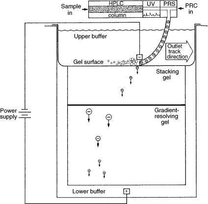
In 1988, Burton et al. developed a new analytical technique which they dubbed the “chromatophoresis” process. This method coupled reverse-phase (RP) highperformance liquid chromatography (HPLC) with SDS – PAGE in an automated system used to separate proteins. Chromatophoresis involved a separation based on differences in hydrophobicity in the first dimension and molecular charge in the second. The chromatophoresis process is illustrated in Figure 9.3. After eluting from an HPLC column, proteins were passed into a heated reaction chamber, where they were denatured and complexed with SDS. The protein complexes in the eluate stream were then deposited onto the surface of a polyacrylamide gradient gel, and an electrophoretic separation subsequently occurred. The five-hour run-time, inconvenience of gel electrophoresis, and difficult detection were the main disadvantages of this technique (11).
9.5 CHROMATOGRAPHY AND ELECTROPHORESIS COMBINED IN NON-COMPREHENSIVE MANNERS
Many groups have used electrophoresis to enhance a primary chromatographic separation. These techniques can be considered to be two-dimensional, but they are not comprehensive, usually due to the loss of resolution in the interface between the two methods. For instance, capillary electrophoresis was used in 1989 by Grossman and co-workers to analyze fractions from an HPLC separation of peptide fragments. In this study, CE was employed for the separation of protein fragments that were not resolved by HPLC. These two techniques proved to be truly orthogonal, since there was no correlation between the retention time in HPLC and the elution order in CE. The analysis time for CE was found to be four times faster than for HPLC (12), which demonstrated that CE is a good candidate for the second dimension in a twodimensional separation system, as will be discussed in more detail later.
In 1989, Yamamoto et al. developed the first technique that directly coupled chromatography to capillary electrophoresis, although again in a non-comprehensive fashion. Low-pressure gel permeation chromatography, which separates analytes based on differences in molecular size, was combined with capillary isotachophoresis, which separates according to electrophoretic mobility. Capillary isotachophoresis
202 |
Multidimensional Chromatography |
Figure 9.3 Schematic illustration of the electrophoretic transfer of proteins in the chromatophoresis process. After being eluted from the HPLC column, the proteins were reduced with -mercaptoethanol in the protein reaction system (PRS), and then deposited onto the polyacrylamide gradient gel. (PRC, protein reaction cocktail). Reprinted from Journal of Chromatography, 443, W. G. Burton et al., ‘Separation of proteins by reversed-phase highperformance liquid chromatography’, pp 363 – 379, copyright 1988, with permission from Elsevier Science.
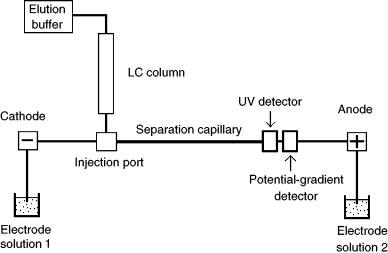
is a moving-boundary CE technique that utilizes leading and trailing electrolytes of differing electrophoretic mobility, between which analytes fraction into distinct zones in order of electrophoretic mobility. Each distinct separated zone is equal in concentration (such that analytes in low initial concentration are focused into a sharp, narrow zone of higher concentration), and all separated zones move at the same velocity. Figure 9.4 shows the coupled apparatus, which had the outlet of the microbore chromatographic column connected to the sample injection port of the electrophoresis capillary. The isotachophoretic run time was 18 min, and this analysis was repeated 60 times within the 18 h chromatographic run. This technique was successfully employed to separate proteins in solution with a stated 200 ng detection
Multidimensional Electrodriven Separations |
203 |
Figure 9.4 General schematic illustration of the apparatus used to combine chromatography with capillary isotachophoresis.
limit, which is comparable to that of polyacrylamide gel electrophoresis. Although this procedure had the possibility of being completely automated, the run time was still quite long (13).
Yamamoto et al. also coupled gel permeation HPLC and CE in an on-line fashion in 1990, where capillary isotachophoresis was again used in the second dimension. This technique was also not comprehensive due to the loss of resolution between the techniques. It was also not particularly fast, with a 23 min CE cycle, which was repeated 90 times throughout the HPLC run (14). Volume incompatibility between HPLC and CE was one problem not addressed in this study, in which a large HPLC column was coupled to an electrophoresis capillary.
Other groups have also used LC and CE to perform non-comprehensive multidimensional separations (15, 16). A three-dimensional separation was performed by Stromqvist in 1994, where size exclusion chromatography (SEC), reverse-phase HPLC, and CZE were used in an off-line manner to separate peptides (17). The most useful information gained from all of these non-comprehensive studies was knowledge of the orthogonality and compatibility of LC and CE.
9.6 COMPREHENSIVE TWO-DIMENSIONAL SEPARATIONS WITH AN ELECTRODRIVEN COMPONENT
The most successful multidimensional electrodriven separations to date have been performed by James Jorgenson and his group at the University of North Carolina at Chapel Hill. This group has accomplished several successful comprehensive

204 |
Multidimensional Chromatography |
Figure 9.5 The generic setup for two-dimensional liquid chromatography–capillary zone electrophoresis as used by Jorgenson’s group. The LC separation was performed in hours, while the CZE runs were on a time scale of seconds.
couplings of different chromatographic methods with capillary zone electrophoresis. Figure 9.5 illustrates the major components of the two-dimensional LC – CZE separation system used by Jorgenson and co-workers (18). The type of LC column (and mode of the separation) and the interface design were both modified many times in order to optimize multidimensional electrodriven separations for various different samples.
9.7 MICROCOLUMN REVERSE PHASE HIGH PERFORMANCE LIQUID CHROMATOGRAPHY– CAPILLARY
ZONE ELECTROPHORESIS
In 1990, Bushey and Jorgenson developed the first automated system that coupled HPLC with CZE (19). This orthogonal separation technique used differences in hydrophobicity in the first dimension and molecular charge in the second dimension for the analysis of peptide mixtures. The LC separation employed a gradient at 20L min volumetric flow rate, with a column of 1.0 mm ID. The effluent from the chromatographic column filled a 10 L loop on a computer-controlled, six-port micro valve. At fixed intervals, the loop material was flushed over the anode end of the CZE capillary, allowing electrokinetic injections to be made into the second dimension from the first.
The HPLC elution time was typically under 260 min, and the CZE analysis took place in 60 s, which led to an overall run time of about 4 h. The 1 min CZE sampling interval was problematic, as the LC column was probably slightly undersampled. A shorter CZE analysis time, which would provide a more frequent sampling rate, would improve this system a great deal. The second-dimension analysis time must be short relative to the first dimension, lest resolution in the first dimension be sacrificed.
Multidimensional Electrodriven Separations |
205 |
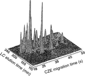
Figure 9.6 Surfer-generated chromatoeletropherogram of fluorescamine-labeled tryptic digest of ovalbumin. Reprinted from Analytical Chemistry, 62, M. M. Bushey and J. W. Jorgenson, ‘Automated instrumentation for comprehensive two-dimensional high-perfor- mance liquid chromatography/capillary zone electrophoresis, pp 978 – 984, copyright 1990, with permission from the American Chemical Society.
An example of the results obtained in the form of a “chromatoelectropherogram” can be seen in Figure 9.6. The contour type data display showed the three variables that were studied, namely chromatographic elution time, electrophoretic migration time, and relative absorbance intensity. Peptides were cleanly resolved by using this two-dimensional method. Neither method alone could have separated the analytes under the same conditions. The most notable feature of this early system was that (presumably) all of the sample components from the first dimension were analyzed by the second dimension, which made this a truly comprehensive multidimensional technique.
In 1993, Jorgenson’s group improved upon their earlier reverse phase HPLC – CZE system. Instead of the six-port valve, they used an eight-port electrically actuated valve that utilized two 10- L loops. While the effluent from the HPLC column filled one loop, the contents of the other loop were injected onto the CZE capillary. The entire effluent from the HPLC column was collected and sampled by CZE, making this too a comprehensive technique, this time with enhanced resolving power. Having the two-loop valve made it possible to overlap the CZE runs. The total CZE run time was 15 s, with peaks occurring between 7.5 and 14.8 s. In order to save separation space, an injection was made into the CZE capillary every 7.5s,
206 |
Multidimensional Chromatography |
therefore overlapping the second-dimension runs. The improved injection scheme resulted in enhancement of the apparent rate of the CZE separation (20).
The only other group to have performed comprehensive multidimensional reverse-phase HPLC – CZE separations is at Hewlett-Packard. In 1996, a two-dimen- sional LC – CE instrument was described at the Frederick Conference on Capillary Electrophoresis by Vonda K. Smith (21). The possibility for a commercial multidimensional instrument may have been explored at that time.
9.8 MICROCOLUMN SIZE EXCLUSION
CHROMATOGRAPHY – CAPILLARY ZONE ELECTROPHORESIS
In 1993, Lemmo and Jorgenson used microcolumn size exclusion chromatography coupled to CZE for the two-dimensional analysis of protein mixtures. Under nondenaturing conditions, SEC provides a description of the molecular weight distribution of a mixture, without destroying the biological activity of the analytes. Microcolumn SEC was chosen due to its reasonable separation efficiency and its ability to interface well with the CZE capillary. Here, a -SEC column of 250 m ID was coupled to a CZE capillary of 50 m ID to generate a comprehensive twodimensional system. System efficiencies of over 100 000 theoretical plates per meter have been obtained through the coupling of these two techniques.
A six-port valve was first used to interface the SEC microcolumn to the CZE capillary in a valve-loop design. UV–VIS detection was employed in this experiment. The overall run time was 2 h, with the CZE runs requiring 9 min. As in the reverse phase HPLC– CZE technique, runs were overlapped in the second dimension to reduce the apparent run time. The main disadvantage of this -SEC – CZE method was the valve that was used for interfacing. The six-port valve contributed a substantial extracolumn volume, and required a fixed volume of 900 nL of effluent from the chromatographic column for each CZE run. The large fixed volume imposed restrictions on the operating conditions of both of the separation methods. Specifically, to fill the 900 nL volume, the SEC flow rate had to be far above the optimum level and therefore the SEC efficiency was decreased (22).
The second interface design that was developed for use with -SEC – CZE used the internal rotor of a valve for the collection of effluent from the SEC microcolumn. The volume collected was reduced to 500 nL, which increased the resolution when compared to the valve-loop interface (20). However, a fixed volume again presented the same restrictions on the SEC and CZE operating parameters. An entirely different approach to the interface design was necessary to optimize the conditions in both of the microcolumns.
Lemmo and Jorgenson developed a third interface for -SEC – CZE in 1993. This design used a transverse flow of CZE buffer to prevent electromigration injections from occurring into the CZE capillary until the appropriate time. Figure 9.7 shows a block diagram of the “flow-gating interface” (18). The interface consisted of a Teflon

Multidimensional Electrodriven Separations |
207 |
Figure 9.7 Schematic illustration of the flow-gating interface. A channeled Teflon gasket was sandwiched between two stainless steel plates to allow for flow into the electrophoresis capillary, either from the flush buffer reservoir or from the LC microcolumn during an electrokinetic injection.
gasket that separated two stainless steel plates. A channel cut into the Teflon allowed buffer to flow between the two plates, except when an injection was made. In comparison to a valve-loop interface, the flow gating interface delivered a more concentrated sample to the capillary, which resulted in an eight fold improvement in sensitivity. This design also allowed the CZE capillary to sample each of the SEC peaks at least three times and therefore the chromatographic column was not undersampled (23).
9.9 PACKED CAPILLARY REVERSE PHASE HIGH PERFORMANCE LIQUID CHROMATOGRAPHY– CAPILLARY ZONE ELECTROPHORESIS
The increased efficiency observed with -SEC – CZE led to the coupling of packed capillary reverse phase HPLC with CZE in order to separate mixtures of peptides. The contents of single cells were separated and detected by using this powerful technique. The reverse phase HPLC microcolumn used was 60 cm long, 50 m in inner diameter, and was packed with a C8 modified silica packing material. Laser induced fluorescence detection of tetramethylrhodamine isothiocyanate-derived amines was used in this method. UV–VIS could not be used due to the extremely short pathlength and lack of sensitivity. A two-dimensional peak capacity of 20 000 was achieved by using this system (18). The reverse phase HPLC microcolumn used in this setup was more compatible with the CZE capillary in terms of volumetric flow and sampling volume than the larger LC columns used in the previous LC-CZE systems.
208 |
Multidimensional Chromatography |
9.10 PACKED CAPILLARY REVERSE PHASE HIGH PERFORMANCE LIQUID CHROMATOGRAPHY– FAST CAPILLARY ZONE ELECTROPHORESIS
In order to improve the speed of CZE analysis, Monnig and Jorgenson developed oncolumn sample gating in 1991. The gating procedure allowed for rapid and automated sample introduction into the CZE capillary. In traditional CZE techniques, a plug of material is mechanically introduced at one end of the capillary, thus yielding a relatively slow sampling rate. In the on-column optical gating method, analytes were first tagged with fluorescein isothiocyanate, a fluorescent label, and then continuously introduced into one end of the capillary. A laser constantly photodegraded the tag near the entrance of the capillary. A sample zone was created by momentarily blocking the laser so that a narrow plug of fluorescent material was created in the column. This method allowed for the rapid injection to be made while the capillary was maintained at operating voltage.
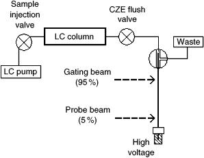
The experimental setup for high-speed CZE can be seen in Figure 9.8. Highspeed CZE, or fast CZE (FCZE), yielded 70 000 to 90 000 theoretical plates for the separation of amino acid mixtures. Complete separation was achieved in under 11 s, using a capillary length of 4 cm (24).
In 1995, Moore and Jorgenson used the optically gated CZE system to obtain extremely rapid separations with HPLC coupled to CZE. The rapid CZE analysis made possible more frequent sampling of the HPLC column, thus increasing the comprehensive resolving power. Complete two-dimensional analyses were performed in less than 10 min, with the CZE analyses requiring only 2.5s. A peak
Figure 9.8 Schematic illustration of the two-dimensional HPLC/fast – CZE instrumental setup. The argon laser beam was set at 488 nm, which was used to photodegrade and detect the fluorescein isothiocyanate tag.
Multidimensional Electrodriven Separations |
209 |
capacity of 650 was obtained from this HPLC – CZE system. Rapid fingerprinting of proteins was one of the suggested possible applications for this technique (25). The success of this two-dimensional technique led to the possibility of coupling HPLCCZE to other techniques to further increase dimensionality and total peak capacity.
9.11 THREE-DIMENSIONAL SIZE EXCLUSION CHROMATOGRAPHY– REVERSE PHASE LIQUID CHROMATOGRAPHY– CAPILLARY ZONE ELECTROPHORESIS
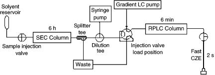
Moore and Jorgenson combined the rapid two-dimensional separation achieved by LC-CZE with SEC to make the first comprehensive three-dimensional separation involving an electrodriven component in 1995. Size exclusion chromatography separated the analytes over a period of several hours while the reverse phase HPLC – CZE combination separated components in only 7 min. A schematic diagram of the threedimensional SEC – reverse phase HPLC – CZE instrument is shown in Figure 9.9 (18). A dilution tee was placed between the SEC column and the reverse phase HPLC injection loop in order to dilute the eluent from the SEC column, since it contained more methanol than was optimal for the reverse phase HPLC column.
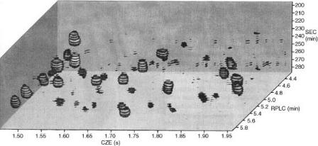
The three-dimensional method was used to separate mixtures of peptides, such as those produced from a tryptic digest of ovalbumin. The three orthogonal characteristics that were used to separate the peptides were size, hydrophobicity, and electrophoretic mobility. A three-dimensional representation of a region of the data gathered can be seen in Figure 9.10. A series of planar slices through the data volume, which form stacks of disks, make it possible to visualize the separation. The peak capacity that resulted from this separation was calculated to be 2800, much greater than the capacities of the individual techniques. The addition of SEC to the original reverse phase HPLC – CZE method increased the peak capacity by a factor of five. One disadvantage of this multidimensional separation system was that extremely concentrated samples had to be used in order to overcome the dilution
Figure 9.9 Schematic illustration of the instrumental setup used for three-dimensional SEC – RPLC – CZE.
210 |
Multidimensional Chromatography |
Figure 9.10 Three-dimensional representation of the data ‘volume’ of a tryptic digest of ovalbumin. Series of planar slices through the data volume produce stacks of disks in order to show peaks. Reprinted from Analytical Chemistry, 67, A. W. Moore Jr and J. W. Jorgenson, ‘Comprehensive three-dimensional separation of peptides using size exclusion chromatography/reversed phase liquid chromatography/optically gated capillary zone electrophoresis,’ pp. 3456 – 3463, copyright 1995, with permission from the American Chemical Society.
inherent in the SEC – reverse phase HPLC interface (26). Another problem evident in this separation was the difficulty in analyzing the data, which is a common problem in multidimensional techniques, particularly those with more than two dimensions.
9.12 TRANSPARENT FLOW GATING INTERFACE WITH PACKED CAPILLARY HIGH PERFORMANCE LIQUID CHROMATOGRAPHY– CAPILLARY ZONE ELECTROPHORESIS
In order to observe the junction between micro-HPLC and CZE in two-dimensional systems, a transparent flow gating interface was developed by Hooker and Jorgenson in 1997. This design was similar to the original flow gating interface, except in the fact that it was made from clear plastic. An illustration of the transparent interface can be seen in Figure 9.11. Direct observation and manipulation of the micro-HPLC and CZE capillaries was made possible by the transparent interface. This new interface created a more routine and reproducible way of interfacing the two microcolumns as compared to the one developed in 1993. The split injection/flow system in the new interface delivered a nanoliter per second flow rate to the -HPLC column from the gradient LC pump, which was yet another improvement in the system.
The improved design of the gating interface resulted in precise alignment of the two capillaries. A colored dye solution was added to the HPLC eluent to allow for direct observation of the flow gating and injection processes. Through observation of the movement of the dye through the interface, it was possible to ensure that the electrokinetic injections were performed correctly. Troubleshooting had been a