

- •Preface
- •Contents
- •1.1 Fundamentals of the semiclassical laser theory
- •1.1.1 The laser oscillator
- •1.1.2.2 Homogeneous, isotropic, linear dielectrics
- •1.1.2.2.1 The plane wave
- •1.1.2.2.2 The spherical wave
- •1.1.2.2.3 The slowly varying envelope (SVE) approximation
- •1.1.2.3 Propagation in doped media
- •1.1.3 Interaction with two-level systems
- •1.1.3.1 The two-level system
- •1.1.3.2 The dipole approximation
- •1.1.3.2.1 Inversion density and polarization
- •1.1.3.3.1 Decay time T1 of the upper level (energy relaxation)
- •1.1.3.3.1.1 Spontaneous emission
- •1.1.3.3.1.2 Interaction with the host material
- •1.1.3.3.1.3 Pumping process
- •1.1.3.3.2 Decay time T2 of the polarization (entropy relaxation)
- •1.1.4 Steady-state solutions
- •1.1.4.1 Inversion density and polarization
- •1.1.4.2 Small-signal solutions
- •1.1.4.3 Strong-signal solutions
- •1.1.5 Adiabatic equations
- •1.1.5.1 Rate equations
- •1.1.5.2 Thermodynamic considerations
- •1.1.5.3 Pumping schemes and complete rate equations
- •1.1.5.3.1 The three-level system
- •1.1.5.3.2 The four-level system
- •1.1.5.5 Rate equations for steady-state laser oscillators
- •1.1.6 Line shape and line broadening
- •1.1.6.1 Normalized shape functions
- •1.1.6.1.1 Lorentzian line shape
- •1.1.6.1.2 Gaussian line shape
- •1.1.6.1.3 Normalization of line shapes
- •1.1.6.2 Mechanisms of line broadening
- •1.1.6.2.1 Spontaneous emission
- •1.1.6.2.2 Doppler broadening
- •1.1.6.2.3 Collision or pressure broadening
- •1.1.6.2.4 Saturation broadening
- •1.1.6.3 Types of broadening
- •1.1.6.3.1 Homogeneous broadening
- •1.1.6.3.2 Inhomogeneous broadening
- •1.1.6.4 Time constants
- •1.1.7 Coherent interaction
- •1.1.7.1 The Feynman representation of interaction
- •1.1.7.3 Propagation of resonant coherent pulses
- •1.1.7.3.2 Superradiance
- •1.1.8 Notations
- •References for 1.1
- •2.1.1 Introduction
- •2.1.3 Radiometric standards
- •2.1.3.1 Primary standards
- •2.1.3.2 Secondary standards
- •References for 2.1
- •2.2 Beam characterization
- •2.2.1 Introduction
- •2.2.2 The Wigner distribution
- •2.2.3 The second-order moments of the Wigner distribution
- •2.2.4 The second-order moments and related physical properties
- •2.2.4.3 Phase paraboloid and twist
- •2.2.4.4 Invariants
- •2.2.4.5 Propagation of beam widths and beam propagation ratios
- •2.2.5.1 Stigmatic beams
- •2.2.5.2 Simple astigmatic beams
- •2.2.5.3 General astigmatic beams
- •2.2.5.4 Pseudo-symmetric beams
- •2.2.5.5 Intrinsic astigmatism and beam conversion
- •2.2.6 Measurement procedures
- •2.2.7 Beam positional stability
- •References for 2.2
- •3 Linear optics
- •3.1 Linear optics
- •3.1.1 Wave equations
- •3.1.2 Polarization
- •3.1.3 Solutions of the wave equation in free space
- •3.1.3.1 Wave equation
- •3.1.3.1.1 Monochromatic plane wave
- •3.1.3.1.2 Cylindrical vector wave
- •3.1.3.1.3 Spherical vector wave
- •3.1.3.2 Helmholtz equation
- •3.1.3.2.1 Plane wave
- •3.1.3.2.2 Cylindrical wave
- •3.1.3.2.3 Spherical wave
- •3.1.3.2.4.2 Real Bessel beams
- •3.1.3.2.4.3 Vectorial Bessel beams
- •3.1.3.3 Solutions of the slowly varying envelope equation
- •3.1.3.3.1 Gauss-Hermite beams (rectangular symmetry)
- •3.1.3.3.2 Gauss-Laguerre beams (circular symmetry)
- •3.1.3.3.3 Cross-sectional shapes of the Gaussian modes
- •3.1.4.4.2 Circular aperture with radius a
- •3.1.4.4.2.1 Applications
- •3.1.4.4.3 Gratings
- •3.1.5 Optical materials
- •3.1.5.1 Dielectric media
- •3.1.5.2 Optical glasses
- •3.1.5.3 Dispersion characteristics for short-pulse propagation
- •3.1.5.4 Optics of metals and semiconductors
- •3.1.5.6 Special cases of refraction
- •3.1.5.6.2 Variation of the angle of incidence
- •3.1.5.7 Crystal optics
- •3.1.5.7.2 Birefringence (example: uniaxial crystals)
- •3.1.5.8 Photonic crystals
- •3.1.5.9 Negative-refractive-index materials
- •3.1.5.10 References to data of linear optics
- •3.1.6 Geometrical optics
- •3.1.6.1 Gaussian imaging (paraxial range)
- •3.1.6.1.1 Single spherical interface
- •3.1.6.1.2 Imaging with a thick lens
- •3.1.6.2.1 Simple interfaces and optical elements with rotational symmetry
- •3.1.6.2.2 Non-symmetrical optical systems
- •3.1.6.2.3 Properties of a system
- •3.1.6.2.4 General parabolic systems without rotational symmetry
- •3.1.6.2.5 General astigmatic system
- •3.1.6.2.6 Symplectic optical system
- •3.1.6.2.7 Misalignments
- •3.1.6.3 Lens aberrations
- •3.1.7 Beam propagation in optical systems
- •3.1.7.2.1 Stigmatic and simple astigmatic beams
- •3.1.7.2.1.1 Fundamental Mode
- •3.1.7.2.1.2 Higher-order Hermite-Gaussian beams in simple astigmatic beams
- •3.1.7.2.2 General astigmatic beam
- •3.1.7.3 Waist transformation
- •3.1.7.3.1 General system (fundamental mode)
- •3.1.7.3.2 Thin lens (fundamental mode)
- •3.1.7.4 Collins integral
- •3.1.7.4.1 Two-dimensional propagation
- •3.1.7.4.2 Three-dimensional propagation
- •3.1.7.5 Gaussian beams in optical systems with stops, aberrations, and waveguide coupling
- •3.1.7.5.1 Field distributions in the waist region of Gaussian beams including stops and wave aberrations by optical system
- •3.1.7.5.2 Mode matching for beam coupling into waveguides
- •3.1.7.5.3 Free-space coupling of Gaussian modes
- •References for 3.1
- •4.1 Frequency conversion in crystals
- •4.1.1 Introduction
- •4.1.1.1 Symbols and abbreviations
- •4.1.1.1.1 Symbols
- •4.1.1.1.2 Abbreviations
- •4.1.1.1.3 Crystals
- •4.1.1.2 Historical layout
- •4.1.2 Fundamentals
- •4.1.2.1 Three-wave interactions
- •4.1.2.2 Uniaxial crystals
- •4.1.2.3 Biaxial crystals
- •4.1.2.5.1 General approach
- •4.1.3 Selection of data
- •4.1.5 Sum frequency generation
- •4.1.7 Optical parametric oscillation
- •4.1.8 Picosecond continuum generation
- •References for 4.1
- •4.2 Frequency conversion in gases and liquids
- •4.2.1 Fundamentals of nonlinear optics in gases and liquids
- •4.2.1.1 Linear and nonlinear susceptibilities
- •4.2.1.2 Third-order nonlinear susceptibilities
- •4.2.1.3 Fundamental equations of nonlinear optics
- •4.2.1.4 Small-signal limit
- •4.2.1.5 Phase-matching condition
- •4.2.2 Frequency conversion in gases
- •4.2.2.1 Metal-vapor inert gas mixtures
- •4.2.2.3 Mixtures of gaseous media
- •References for 4.2
- •4.3 Stimulated scattering
- •4.3.1 Introduction
- •4.3.1.1 Spontaneous scattering processes
- •4.3.1.2 Relationship between stimulated Stokes scattering and spontaneous scattering
- •4.3.2 General properties of stimulated scattering
- •4.3.2.1 Exponential gain by stimulated Stokes scattering
- •4.3.2.2 Experimental observation
- •4.3.2.2.1 Generator setup
- •4.3.2.2.2 Oscillator setup
- •4.3.2.3 Four-wave interactions
- •4.3.2.3.1 Third-order nonlinear susceptibility
- •4.3.2.3.3 Higher-order Stokes and anti-Stokes emission
- •4.3.2.4 Transient stimulated scattering
- •4.3.3 Individual scattering processes
- •4.3.3.1 Stimulated Raman scattering (SRS)
- •4.3.3.2 Stimulated Brillouin scattering (SBS) and stimulated thermal Brillouin scattering (STBS)
- •4.3.3.3 Stimulated Rayleigh scattering processes, SRLS, STRS, and SRWS
- •References for 4.3
- •4.4 Phase conjugation
- •4.4.1 Introduction
- •4.4.2 Basic mathematical description
- •4.4.3 Phase conjugation by degenerate four-wave mixing
- •4.4.4 Self-pumped phase conjugation
- •4.4.5 Applications of SBS phase conjugation
- •4.4.6 Photorefraction
- •References for 4.4
Ref. p. 245] |
4.4 Phase conjugation |
235 |
|
|
|
4.4 Phase conjugation
H.J. Eichler, A. Hermerschmidt, O. Mehl
4.4.1 Introduction
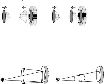
Phase conjugation is a nonlinear optical process which generates a light beam having the same wavefronts as an incoming light beam but opposite propagation direction, see Fig. 4.4.1. Therefore phase conjugation is also called wavefront reversal. A nonlinear optical device generating a phaseconjugated wave is called a phase conjugator or Phase-Conjugate Mirror (PCM ).
e i ( r) |
e i ( r) |
e i ( r) |
e -i ( r) |
|
|
|
|
|
|
|
|
|
Fig. 4.4.1. Wavefront reflection at a conven- |
Conventional mirror |
Phase-conjugate mirror |
tional mirror and at a phase-conjugate mirror |
|
(PCM). |
|||
In Fig. 4.4.2 we consider the conjugation property of a PCM on a probe wave emanating from a point source. A diverging beam, after “reflection” from an ideal PCM, gives rise to a converging conjugate wave that precisely retraces the path of the incident probe wave, and therefore propagates in a time-reversed sense back to the same initial point source.
kkout
kout==- kin
kin
Conventional mirror |
Phase conjugate mirror |
Conventional mirror |
Phase-conjugate mirror |
Fig. 4.4.2. Beam propagation after reflection at a conventional mirror and a PCM, both illuminated by a point source.
A phase conjugator reflects light, mostly laser beams, only if the incident power is high enough (self-pumped phase conjugator ) or if the nonlinear material in the phase conjugator is pumped by additional laser beams, e.g. two additional beams in a degenerate four-wave mixing arrangement. In principle phase conjugation could be achieved also by a deformable mirror which is controlled by a wavefront sensor adapting the local mirror curvature to the incoming wavefront. Instead of a deformable mirror also a 2-dimensional phase modulator could be used. However, deformable mirrors and other phase modulators up to now are more complicated set-ups with longer reaction periods than nonlinear optical phase conjugators to solve practical problems requiring phase conjugation.
Landolt-B¨ornstein
New Series VIII/1A1
236 |
4.4.3 Phase conjugation by degenerate four-wave mixing |
[Ref. p. 245 |
|
|
|
4.4.2 Basic mathematical description
The incoming wave Ein is given by (4.4.1) with frequency f , where the amplitude E0 and phase Φ are combined to the complex amplitude A. The complex conjugate is denoted by c.c.
Ein(x, y, z, t) = |
1 |
E0(x, y, z) e2 π i (f t+Φ(x,y,z)) |
+ c.c. = A(x, y, z) ei ωt + c.c. , |
(4.4.1) |
|||
2 |
|||||||
|
|
|
|
|
|
||
A(x, y, z) = |
1 |
E0(x, y, z) e2 π i Φ(x,y,z) . |
|
(4.4.2) |
|||
2 |
|
||||||
|
|
|
|
|
|
||
The phase-conjugated wave exhibits the same wavefronts, however the sign of the phase Φ is inverted due to the inverted propagation direction. Thus, the phase-conjugated wave Epc can be
written as (4.4.3): |
|
|
|
|
|
|
Epc(x, y, z, t) = |
|
1 |
E0(x, y, z) e2 π i (f t−Φ(x,y,z)) + c.c. = Apc(x, y, z) ei ωt + c.c. , |
(4.4.3) |
||
2 |
||||||
|
|
|
|
|||
Apc(x, y, z) = |
1 |
E0(x, y, z) e−2 π i Φ(x,y,z) = A (x, y, z) . |
(4.4.4) |
|||
2 |
||||||
|
|
|
|
|
||
As can be seen Apc equals the complex-conjugated A , which explains the term phase conjugation. From (4.4.1) and (4.4.3) we derive that the incident and phase-conjugated wave are also related to each other by
Ein(x, y, z, −t) = Epc(x, y, z, t) . |
(4.4.5) |
Thus, the phase-conjugate wave Epc propagates as if one would reverse the temporal evolution of the incident wave Ein . Therefore the term “time-reversed replica” is sometimes used to describe the phase-conjugate wave.
An ideal PCM also maintains the polarization state of an incident wave after phase conjugation. As an example, a probe wave that is Right-Handed Circularly Polarized (RHCP) will result in a RHCP-reflected wave after conjugation. This is in contrast to a conventional mirror, which reflects an incident RHCP field to yield a Left-Handed Circularly Polarized (LHCP) wave [82Pep].
One should realize that an ideal phase-conjugated wave exhibits the same frequency f as the incident wave and reveals the same polarization state. Often, real phase conjugators do not have these properties. However, if an PCM maintains the polarization state it is called a “vector phase conjugator ”.
The nonlinear optical process which comes closest to yielding an ideal phase-conjugate wave is the backward-going, degenerate four-wave mixing interaction. Other classes of interaction (e.g. stimulated e ects) result in nonideal conjugate waves due to frequency shifts, nonconjugated field polarization, etc. Although the application of stimulated e ects, especially Stimulated Brillouin Scattering (SBS), yields to nonideal phase-conjugate mirrors they are used the most to solve practical problems requiring phase conjugation (e.g. compensation of phase distortions in high average power laser systems [99Eic]).
4.4.3 Phase conjugation by degenerate four-wave mixing
Four-wave mixing can be understood as a real-time holographic process, which facilitates phase conjugation. If the frequencies of the incoming wave, the two additionally required pump waves, and the phase-conjugated or reflected wave are equal the process is called Degenerate Four-Wave Mixing (DFWM ).
Landolt-B¨ornstein
New Series VIII/1A1

Ref. p. 245] |
4.4 Phase conjugation |
237 |
|
|
|
Pump wave P1  Pump wave P2
Signal wave |
Phase-conjugate wave |
Fig. 4.4.3. Setup for phase conjugation by four-wave mix- |
|
ing. |
|||
|
|
In Fig. 4.4.3 the setup for phase conjugation by four-wave mixing is shown.
Interference of the incoming wave Ein(x, y, z, t) with the pump wave P1(x, y, z, t) results in a spatially periodic intensity pattern which modulates the absorption coe cient or refractive index of the optical material resulting in a dynamic or transient amplitude or phase grating. The other pump P2(x, y, z, t) is di racted at this grating producing the phase-conjugated wave. This corresponds to the conventional holographic process where the read-out wave is replaced by the second pump wave counterpropagating to the first pump or reference wave.
Recording of a hologram is the first step in phase conjugation and leads to a transmission function t in the hologram plane (variables will not be noted furthermore to simplify the readability):
t |
| |
P |
1 |
+ E |
in| |
2 |
= |
· · · |
= |
P |
1 |
| |
2 + P |
E |
+ P E |
in |
+ |
E |
2 . |
(4.4.6) |
|
|
|
|
|
| |
|
1 |
in |
1 |
| |
|
in| |
|
During the read-out the phase-conjugate wave can be generated. Therefore, the hologram is illuminated with a second pump wave P2 , propagating in the opposite direction to P1 . This is in contrast to standard holography. Since P2 precisely retraces the path of P1 in the opposite propagation direction, P2 equals P1 . This means, that the two pump beams should be phase-conjugated to each other, so that their spatial phases cancel and do not influence the phases of the reflected beam.
In the hologram plane we obtain a field strength distribution as follows:
P |
2 |
t = P t |
|
P |
P |
1 |
| |
2 + |
P |
1 |
| |
2 E |
+ (P )2 |
E |
in |
+ P |
E |
in| |
2 . |
(4.4.7) |
|
1 |
1 | |
|
| |
|
in |
1 |
|
1 | |
|
|
|
The second term |P1|2 Ein corresponds to the phase-conjugate wave of Ein . The other expressions lead to three additional waves which are not of interest here. They can be suppressed in thick nonlinear media in case of Bragg di raction.
Common dynamic grating materials for phase conjugation are:
–photorefractive crystals (LiNbO3, BaTiO3, . . . ),
–liquid crystals (molecular reorientation e ects),
–laser crystals (spatial hole-burning, excited-state absorption),
–saturable absorbers,
–absorbing gases and liquids (thermal gratings),
–semiconductors (Si, GaAs, . . . ).
The disadvantage of phase conjugation by four-wave mixing is the requirement of two additional pump waves for the nonlinear medium. However, this facilitates amplification of the phaseconjugate wave in the nonlinear medium at the same time. Vector phase conjugation is not achieved by this simple DFWM scheme, but requires polarization-dependant interactions.
4.4.4 Self-pumped phase conjugation
Self-pumped phase conjugation of continuous-wave laser beams in the lower power range (mW . . . W) can be realized in Four-Wave Mixing (FWM) loop arrangements using photorefractive media, see Sect. 4.4.6 for detailed discussion.
Landolt-B¨ornstein
New Series VIII/1A1

238 |
4.4.4 Self-pumped phase conjugation |
[Ref. p. 245 |
|
|
|
Table 4.4.1. Brillouin gain coe cient g and phonon lifetime τ for di erent SBS media.
SBS medium |
Brillouin gain coe cient g [cm/GW] |
Phonon lifetime τ [ns] |
|
|
|
SF6 (20 bar) |
25 |
15 |
Xe (50 bar) |
90 |
33 |
C2F6 (30 bar) |
60 |
10 |
CS2 |
130 |
5.2 |
CCl4 |
6 |
0.6 |
Acetone |
20 |
2.1 |
Quartz |
2.4 |
5 |
|
|
|
For pulsed lasers, self-pumped phase conjugation is achieved by stimulated scattering. For practical application, stimulated Brillouin scattering [72Kai] in
–gases (SF6, Xe, C2F6, CH4, N2, . . . ) under high pressure,
–liquids (CS2, CCl4, acetone, freon, GeCl4, methanol, . . . ), and
–solids (bulk quartz glass, glass fibers)
is used.
Table 4.4.1 shows the Brillouin gain coe cient g and the phonon lifetime τ for di erent gaseous, liquid, and solid-state SBS media.
A phase-conjugate mirror consists simply of a gas or liquid cell or a fiber piece. The incoming wave is focused into the material where an oppositely traveling wave is generated initially by spontaneous scattering. This wave interferes with the incoming wave and induces a sound wave or another type of phase grating reflecting the incoming beam similarly as a dielectric multilayer mirror. The induced density variations have the frequency of the initial sound wave, which is amplified therefore and reinforces the backscattering. A detailed discussion of stimulated Brillouin scattering is given in Sect. 4.3.3.2.
The amplification depends strongly on the extension of the interference area. Therefore the phase-conjugated backscattered part dominates, leading to an exponential rise of the reflected phase-conjugated signal. The wavefronts of the sound-wave grating match the wavefronts of the incoming beam. Any disturbance of the incident wavefront will result in a self-adapted mirror curvature with response times in the ns range.
For applications the “threshold”, reflectivity, and conjugation fidelity are the most important parameters that characterize the performance of a Brillouin-scattering phase-conjugate mirror. A sharply defined threshold does not exist for the nonlinear SBS process. However, after exceeding a certain input energy a steep increase of reflectivity can be observed. Often this is called the energy threshold of the phase-conjugate medium. For long pulses as compared to the phonon lifetime (typically several ns) the SBS is expected to become stationary. In this case the energy threshold can be substituted by a power threshold. Well above this threshold, the reflectivity is not stationary but exhibits statistical fluctuations because SBS starts from noise.
It is important to emphasize that the power and not the intensity determines the “threshold” in case of strongly monochromatic input waves. Slight focusing leads to lower intensity, but also to a longer Rayleigh length and a larger interaction area. Stronger focusing reduces the interaction length, but results in stronger refractive-index modulation. Both e ects compensate each other if the interaction length is not limited by the coherence length.
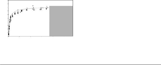
Practically, for most laser sources the coherence length is rather short. Here the interaction length should be short compared to the coherence length. This requires adequate focusing of the beam into the SBS medium. Focal length and scattering material have to be chosen suitable to achieve a high SBS reflectivity and a good reproduction of the wavefront. Side e ects in the material like absorption, optical breakdown, or other scattering processes have to be avoided. Figure 4.4.4
Landolt-B¨ornstein
New Series VIII/1A1
Ref. p. 245] |
4.4 Phase conjugation |
239 |
|
|
|
Energy reflectivity [ %]
100
80
60
40
20
0
Pulse width: 12 ns= 1 m
|
Optical breakdown: |
Carbon disulfide |
1011_1012 W cm 2 |
0.5 |
1.0 |
1.5 |
2.0 |
2.5 |
|
Input power [MW] |
|
||
Fig. 4.4.4. Commonly used carbon disulfide (CS2) shows an SBS threshold of about 18 kW (pulse peak power) under stationary conditions.
Table 4.4.2. SBS threshold, max. reflectivity, far-field fidelity, M 2-limit, and power limit for di erent fiber phase conjugators, coherence length 1.5 m. The reflectivity is corrected with respect to Fresnel and coupling losses.
Core diameter |
SBS threshold |
Maximum reflectivity |
Far-field fidelity |
M 2-limit |
Power limit |
[µm] |
[kW] |
[%] |
[%] |
|
[kW] |
|
|
|
|
|
|
200 |
17 |
80 |
93 |
63 |
160 |
100 |
6.4 |
80 |
91 |
31 |
40 |
50 |
2.0 |
88 |
70 |
16 |
10 |
25 |
0.3 |
86 |
– |
8 |
2.5 |
|
|
|
|
|
|
shows the energy reflectivity of carbon disulfide as a function of the input power at 1 µm wavelength. Carbon disulphide shows one of the smallest power thresholds for liquids of about 18 kW. Applying gases as SBS media, the power thresholds are about one order of magnitude higher. A saturation of energy reflectivity close to 80 % is a typical value for liquid SBS media, although reflectivities up to 96 % had been demonstrated [91Cro].
For high-power input pulses bulk solid-state media like quartz are investigated as SBS media, too [97Yos]. To reduce the power threshold of SBS a waveguide geometry can be applied [95Jac]. The beam intensity inside the waveguide is high within a long interaction length resulting in low power thresholds. To avoid toxic liquids and gases under high pressure multimode quartz fibers can be used [97Eic]. The lower Brillouin gain of quartz glass compared to suitable SBS gases and liquids can be overcome using fibers with lengths of several meters resulting in SBS thresholds down to 200 W peak power [98Eic].
The power threshold Pth can be estimated from (4.4.8), where Ae is the e ective mode field area inside the fiber core, Le the e ective interaction length, which depends on the coherence length, and g is the Brillouin gain coe cient; for quartz g is about 2.4 cm/GW [89Agr].
Pth = |
21 Ae |
. |
(4.4.8) |
|
|||
|
Le g |
|
|
Table 4.4.2 shows the power threshold, the maximum energy reflectivity, the far-field fidelity, the M 2-limit (see below), and an approximated power limit of fiber phase conjugators with di erent core diameters. The used quartz-quartz fibers had a step-index geometry and a numerical aperture of 0.22. They were investigated with an Nd:YAG oscillator amplifier system generating pulses of 30 ns (FWHM) at 1.06 µm wavelength. Regarding applications it is important to couple also spatially aberrated beams into the fiber. The upper limit for the beam parameter product is due to the finite numerical aperture and the core diameter of the fiber. This can by expressed by a “times di raction limit value” M 2, see Chap. 2.2 for further information about beam characterization. The upper power limit is approximated assuming a damage threshold above 500 MW/cm2 for ns pulses.
Landolt-B¨ornstein
New Series VIII/1A1