

- •Preface
- •Contents
- •1.1 Fundamentals of the semiclassical laser theory
- •1.1.1 The laser oscillator
- •1.1.2.2 Homogeneous, isotropic, linear dielectrics
- •1.1.2.2.1 The plane wave
- •1.1.2.2.2 The spherical wave
- •1.1.2.2.3 The slowly varying envelope (SVE) approximation
- •1.1.2.3 Propagation in doped media
- •1.1.3 Interaction with two-level systems
- •1.1.3.1 The two-level system
- •1.1.3.2 The dipole approximation
- •1.1.3.2.1 Inversion density and polarization
- •1.1.3.3.1 Decay time T1 of the upper level (energy relaxation)
- •1.1.3.3.1.1 Spontaneous emission
- •1.1.3.3.1.2 Interaction with the host material
- •1.1.3.3.1.3 Pumping process
- •1.1.3.3.2 Decay time T2 of the polarization (entropy relaxation)
- •1.1.4 Steady-state solutions
- •1.1.4.1 Inversion density and polarization
- •1.1.4.2 Small-signal solutions
- •1.1.4.3 Strong-signal solutions
- •1.1.5 Adiabatic equations
- •1.1.5.1 Rate equations
- •1.1.5.2 Thermodynamic considerations
- •1.1.5.3 Pumping schemes and complete rate equations
- •1.1.5.3.1 The three-level system
- •1.1.5.3.2 The four-level system
- •1.1.5.5 Rate equations for steady-state laser oscillators
- •1.1.6 Line shape and line broadening
- •1.1.6.1 Normalized shape functions
- •1.1.6.1.1 Lorentzian line shape
- •1.1.6.1.2 Gaussian line shape
- •1.1.6.1.3 Normalization of line shapes
- •1.1.6.2 Mechanisms of line broadening
- •1.1.6.2.1 Spontaneous emission
- •1.1.6.2.2 Doppler broadening
- •1.1.6.2.3 Collision or pressure broadening
- •1.1.6.2.4 Saturation broadening
- •1.1.6.3 Types of broadening
- •1.1.6.3.1 Homogeneous broadening
- •1.1.6.3.2 Inhomogeneous broadening
- •1.1.6.4 Time constants
- •1.1.7 Coherent interaction
- •1.1.7.1 The Feynman representation of interaction
- •1.1.7.3 Propagation of resonant coherent pulses
- •1.1.7.3.2 Superradiance
- •1.1.8 Notations
- •References for 1.1
- •2.1.1 Introduction
- •2.1.3 Radiometric standards
- •2.1.3.1 Primary standards
- •2.1.3.2 Secondary standards
- •References for 2.1
- •2.2 Beam characterization
- •2.2.1 Introduction
- •2.2.2 The Wigner distribution
- •2.2.3 The second-order moments of the Wigner distribution
- •2.2.4 The second-order moments and related physical properties
- •2.2.4.3 Phase paraboloid and twist
- •2.2.4.4 Invariants
- •2.2.4.5 Propagation of beam widths and beam propagation ratios
- •2.2.5.1 Stigmatic beams
- •2.2.5.2 Simple astigmatic beams
- •2.2.5.3 General astigmatic beams
- •2.2.5.4 Pseudo-symmetric beams
- •2.2.5.5 Intrinsic astigmatism and beam conversion
- •2.2.6 Measurement procedures
- •2.2.7 Beam positional stability
- •References for 2.2
- •3 Linear optics
- •3.1 Linear optics
- •3.1.1 Wave equations
- •3.1.2 Polarization
- •3.1.3 Solutions of the wave equation in free space
- •3.1.3.1 Wave equation
- •3.1.3.1.1 Monochromatic plane wave
- •3.1.3.1.2 Cylindrical vector wave
- •3.1.3.1.3 Spherical vector wave
- •3.1.3.2 Helmholtz equation
- •3.1.3.2.1 Plane wave
- •3.1.3.2.2 Cylindrical wave
- •3.1.3.2.3 Spherical wave
- •3.1.3.2.4.2 Real Bessel beams
- •3.1.3.2.4.3 Vectorial Bessel beams
- •3.1.3.3 Solutions of the slowly varying envelope equation
- •3.1.3.3.1 Gauss-Hermite beams (rectangular symmetry)
- •3.1.3.3.2 Gauss-Laguerre beams (circular symmetry)
- •3.1.3.3.3 Cross-sectional shapes of the Gaussian modes
- •3.1.4.4.2 Circular aperture with radius a
- •3.1.4.4.2.1 Applications
- •3.1.4.4.3 Gratings
- •3.1.5 Optical materials
- •3.1.5.1 Dielectric media
- •3.1.5.2 Optical glasses
- •3.1.5.3 Dispersion characteristics for short-pulse propagation
- •3.1.5.4 Optics of metals and semiconductors
- •3.1.5.6 Special cases of refraction
- •3.1.5.6.2 Variation of the angle of incidence
- •3.1.5.7 Crystal optics
- •3.1.5.7.2 Birefringence (example: uniaxial crystals)
- •3.1.5.8 Photonic crystals
- •3.1.5.9 Negative-refractive-index materials
- •3.1.5.10 References to data of linear optics
- •3.1.6 Geometrical optics
- •3.1.6.1 Gaussian imaging (paraxial range)
- •3.1.6.1.1 Single spherical interface
- •3.1.6.1.2 Imaging with a thick lens
- •3.1.6.2.1 Simple interfaces and optical elements with rotational symmetry
- •3.1.6.2.2 Non-symmetrical optical systems
- •3.1.6.2.3 Properties of a system
- •3.1.6.2.4 General parabolic systems without rotational symmetry
- •3.1.6.2.5 General astigmatic system
- •3.1.6.2.6 Symplectic optical system
- •3.1.6.2.7 Misalignments
- •3.1.6.3 Lens aberrations
- •3.1.7 Beam propagation in optical systems
- •3.1.7.2.1 Stigmatic and simple astigmatic beams
- •3.1.7.2.1.1 Fundamental Mode
- •3.1.7.2.1.2 Higher-order Hermite-Gaussian beams in simple astigmatic beams
- •3.1.7.2.2 General astigmatic beam
- •3.1.7.3 Waist transformation
- •3.1.7.3.1 General system (fundamental mode)
- •3.1.7.3.2 Thin lens (fundamental mode)
- •3.1.7.4 Collins integral
- •3.1.7.4.1 Two-dimensional propagation
- •3.1.7.4.2 Three-dimensional propagation
- •3.1.7.5 Gaussian beams in optical systems with stops, aberrations, and waveguide coupling
- •3.1.7.5.1 Field distributions in the waist region of Gaussian beams including stops and wave aberrations by optical system
- •3.1.7.5.2 Mode matching for beam coupling into waveguides
- •3.1.7.5.3 Free-space coupling of Gaussian modes
- •References for 3.1
- •4.1 Frequency conversion in crystals
- •4.1.1 Introduction
- •4.1.1.1 Symbols and abbreviations
- •4.1.1.1.1 Symbols
- •4.1.1.1.2 Abbreviations
- •4.1.1.1.3 Crystals
- •4.1.1.2 Historical layout
- •4.1.2 Fundamentals
- •4.1.2.1 Three-wave interactions
- •4.1.2.2 Uniaxial crystals
- •4.1.2.3 Biaxial crystals
- •4.1.2.5.1 General approach
- •4.1.3 Selection of data
- •4.1.5 Sum frequency generation
- •4.1.7 Optical parametric oscillation
- •4.1.8 Picosecond continuum generation
- •References for 4.1
- •4.2 Frequency conversion in gases and liquids
- •4.2.1 Fundamentals of nonlinear optics in gases and liquids
- •4.2.1.1 Linear and nonlinear susceptibilities
- •4.2.1.2 Third-order nonlinear susceptibilities
- •4.2.1.3 Fundamental equations of nonlinear optics
- •4.2.1.4 Small-signal limit
- •4.2.1.5 Phase-matching condition
- •4.2.2 Frequency conversion in gases
- •4.2.2.1 Metal-vapor inert gas mixtures
- •4.2.2.3 Mixtures of gaseous media
- •References for 4.2
- •4.3 Stimulated scattering
- •4.3.1 Introduction
- •4.3.1.1 Spontaneous scattering processes
- •4.3.1.2 Relationship between stimulated Stokes scattering and spontaneous scattering
- •4.3.2 General properties of stimulated scattering
- •4.3.2.1 Exponential gain by stimulated Stokes scattering
- •4.3.2.2 Experimental observation
- •4.3.2.2.1 Generator setup
- •4.3.2.2.2 Oscillator setup
- •4.3.2.3 Four-wave interactions
- •4.3.2.3.1 Third-order nonlinear susceptibility
- •4.3.2.3.3 Higher-order Stokes and anti-Stokes emission
- •4.3.2.4 Transient stimulated scattering
- •4.3.3 Individual scattering processes
- •4.3.3.1 Stimulated Raman scattering (SRS)
- •4.3.3.2 Stimulated Brillouin scattering (SBS) and stimulated thermal Brillouin scattering (STBS)
- •4.3.3.3 Stimulated Rayleigh scattering processes, SRLS, STRS, and SRWS
- •References for 4.3
- •4.4 Phase conjugation
- •4.4.1 Introduction
- •4.4.2 Basic mathematical description
- •4.4.3 Phase conjugation by degenerate four-wave mixing
- •4.4.4 Self-pumped phase conjugation
- •4.4.5 Applications of SBS phase conjugation
- •4.4.6 Photorefraction
- •References for 4.4
240 |
4.4.5 Applications of SBS phase conjugation |
[Ref. p. 245 |
|
|
|
An important feature of a fiber phase conjugator is the threshold behavior for di erent M 2- values of the incoming beam. In case of a fiber the SBS threshold is nearly independent of the incoming beam quality. This is caused by mode conversion inside the fiber resulting in homogeneous illumination and therefore in constant SBS reflectivity. In case of a Brillouin cell the reflectivity depends on the far-field distribution of the incoming beam. Here phase distortions result in amplitude fluctuations in the focal region. A comparison between a di raction-limited beam (M 2 = 1.0) and a highly distorted beam (M 2 = 10) showed an increase of the SBS threshold of 300 % in case of the Brillouin cell. For the fiber phase conjugator no remarkable changes of the power threshold were observed [97Eic].
Practically, the reproduction of the initial wavefront is not perfect after phase conjugation. To characterize the deviation with respect to the reference wave the term fidelity F is introduced [77Zel]:
|
|
|
E |
|
E d2 r |
2 |
|
|
||||
|
|
|
in |
|
p |
|
p |
|
|
|
||
|
|
|
|
|
|
|
|
|
|
|
||
F = |
| |
|
| |
|
|
· |
| |
|
| |
. |
(4.4.9) |
|
|
Ein |
|
2d2 r |
|
E |
|
|
|||||
|
|
|
|
|
|
|
|
|
|
|
|
|
The fidelity equals unity in case of perfect wavefront reproduction and is smaller than unity for practical cases. To calculate the fidelity, the electric field distribution of the incident signal Ein and the not perfectly phase-conjugated wave Ep – the perfectly phase-conjugated wave is denoted Epc in Sect. 4.4.2 – has to be known. The determination requires sophisticated measurement equipment. In contrary, the far-field fidelity can be measured with less e ort and is therefore often used. The transmission through an aperture of the phase-conjugate signal is compared with the transmission of the input signal. The ratio is called far-field fidelity, because the aperture is placed in the focal plane of a focusing lens.
4.4.5 Applications of SBS phase conjugation
Phase conjugation generates a wave which retraces the incoming wave in a time-reversed way. Thereby it is possible to eliminate phase distortions in optical systems. For example, in a solidstate laser amplifier, the incoming beam is not only amplified but su ers also from phase distortions due to thermal refractive-index changes in the laser crystal. After passing this amplifier crystal, the beam is reflected by a phase conjugator and passes the crystal a second time. As the wavefronts are inverted with respect to the propagation direction, the refractive-index changes reduce the phase distortions and after the second passage, these distortions disappear so that the beam quality of the incoming wave is reproduced. In Fig. 4.4.5 a double-pass scheme with phase-conjugate mirror to compensate for phase distortions is shown.
Typically, phase conjugators are applied in Master Oscillator Power Amplifier (MOPA) setups, where a nearly di raction-limited master oscillator beam is increased in power within an amplifier
Amplifier |
|
Conventional |
|
||||
|
|
mirrorr |
|
||||
|
|
|
|
|
|
|
Fig. 4.4.5. Double-pass scheme with phase- |
|
|
|
|
|
|
|
|
|
|
|
|
|
|
|
conjugate mirror to compensate for phase distor- |
Amplifier |
|
|
PCM |
|
|||
|
|
|
tions. |
||||
|
|
|
|
|
|
|
|
Landolt-B¨ornstein
New Series VIII/1A1
Ref. p. 245] |
4.4 Phase conjugation |
241 |
|
|
|
Oscillator
PCM
Amplifier
Amplifier
Rotator Polarizer
Fig. 4.4.6. Master oscillator power amplifier (MOPA) setup with phase-conjugate mirror.
Oscillator output |
Distorted beam after single |
Reconstructed beam |
Oscillator output |
Distorted beam after single |
Reconstructed beam |
|
pass through amplifier |
after double pass |
|
pass through amplifier |
after double pass |
Fig. 4.4.7. Far-field intensity distributions of the oscillator beam, the distorted beam after single-pass amplification, and the highly amplified beam after double-pass amplification with phase conjugation.
arrangement, see Fig. 4.4.6. After the first amplification pass the beam quality is reduced due to thermally induced phase distortions. The spatial-distorted beam enters the SBS mirror and becomes phase-conjugated. The initial beam quality of the master oscillator can be roughly reproduced after the second amplification pass. The amplified beam is extracted with an optical isolation, which consists in this case of a Faraday rotator and a polarizer.
Figure 4.4.6 shows a MOPA system producing up to 210 W average output power at 2 kHz average repetition rate (1.08 µm wavelength). The system is part of an advanced setup yielding up to 520 W average output power [99Eic]. The oscillator beam has a nearly di raction-limited
beam quality (M 2 < 1.2) which is already reduced in front of the first amplifier (M 2 1.5). This
=
results from optical components between oscillator and amplifier which introduce phase distortions.
After single-pass amplification the beam quality decreases to M 2 5 due to phase distortions
=
introduced by both pumped amplifier rods at 6.5 kW pumping power for each amplifier. After phase conjugation and double-pass amplification the initial beam quality can be nearly reproduced (M 2 < 1.9). Di erences between the initial and final beam quality are caused by a fidelity smaller than unity and di raction at several apertures in the amplifier chain.
The performance of the phase-conjugate mirror can be illustrated by far-field intensity profiles recorded at di erent positions in the setup. In Fig. 4.4.7 the oscillator output beam exhibits a smooth Gaussian profile corresponding to the nearly di raction-limited beam quality. After singlepass amplification the reduction of beam quality is confirmed by a strongly aberrated far-field profile. After phase conjugation and double-pass amplification the initial intensity distribution can be nearly reproduced. In this example the average power of the master oscillator beam (approx. 1 W) was increased to 130 W after double-pass amplification.
Presently, phase distortion elimination in double or multipass laser amplifiers is the most often application of phase conjugation. In addition phase conjugators are useful as mirrors in laser oscillators replacing one of the conventional mirrors. Again, the phase conjugator eliminates phase distortions in the laser medium induced by optical or discharge pumping. For recent advances and applications of SBS-phase-conjugation see [02Eic, 03Rie, 04Rie].
Landolt-B¨ornstein
New Series VIII/1A1
242 |
4.4.6 Photorefraction |
[Ref. p. 245 |
|
|
|
4.4.6 Photorefraction
The photorefractive e ect belongs to the nonlinear optical e ects with the highest sensitivity for operation at low optical intensity levels. Photorefractive phase conjugators are able to operate using intensities of only mW/cm2. The price paid of the low intensity performance is diminished speed. The response times of recent photorefractive phase conjugators span in the range of milliseconds to several minutes.
The photorefractive e ect describes light-induced refractive-index changes in the material when the incident light is spatially nonuniform [88Gue, 93Yeh, 95Nol, 96Sol]. The spatial nonuniformity distinguishes the photorefractive e ect from other common nonlinear optical e ects that occur under spatial uniform intensity. The maximum refractive-index change induced in a photorefractive material does not occur necessarily locally where the light intensity is a maximum. The nonlocal response occurs because electric charges move and are stored inside the material. In case of classical nonorganic bulk photorefractive materials, such as ferroelectric oxides (BaTiO3, LiNbO3, KNbO3), sillenites (Bi12SiO20, Bi12TiO20, Bi12GeO20) or semi-insulating semiconductors (GaAs, InP, CdTe), electrons (or holes) are photoexcited from localized impurity centers or defect sites, which are energetically located deep in the band gap of the material, into the conduction (or valence) band.
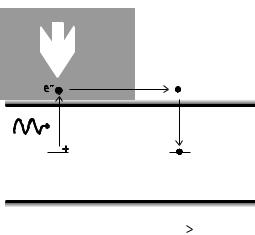
The energy of the exciting photons is smaller than the band-gap energy. Free carriers excited in bright crystal regions move due to di usion and drift into dark crystal regions where they are trapped by empty defect sites, see Fig. 4.4.8. As a consequence of separated and trapped electric charges the formation of space-charge electric fields occurs. These electric fields change the refractive index of the material by electrooptics e ects, usually the Pockels e ect.
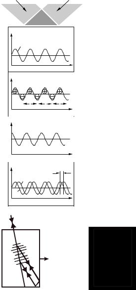
Nonuniform illumination occurs when two coherent laser beams interfere in the crystal. The intersecting beams create a periodical interference pattern. The formation of a photorefractive index grating due to a sinusoidal intensity pattern is shown in Fig. 4.4.9. When di usion is the main e ect for the transport of the excited charge carriers (there is no external electric field applied on the crystal) the electric-field maxima are shifted by a quarter fringe spacing relative to the intensity maxima. This π/2 phase shift of the induced index grating plays a fundamental role in photorefractive non-linear optical wave mixing. It allows for an energy transfer between the two beams writing the grating in a process called two-wave mixing. One of the beams (called signal beam) is amplified at the expense of the other beam (called pump beam).
A phase-conjugate beam can be created by four-wave mixing processes. In this case the two-wave mixing arrangement is extended with a second pump beam which counterpropagates with respect to the first pump beam, see Fig. 4.4.3. In case of external pump beams, the phase-conjugation
Light
e− |
Diffusion, drift |
CB |
|
|
+ |
Trap
VB
E |
Fig. 4.4.8. Band transport model of photorefrac- |
|
tion. |
||
|
Landolt-B¨ornstein
New Series VIII/1A1
Ref. p. 245] |
4.4 Phase conjugation |
243 |
|
|
|
I (x ) |
x |
(x ) |
E |
x |
E ( x ) |
x |
/4 |
n ( x ) |
I ( x ) |
x |
cc aaxiss |
Coherent
beams
Interference
Space charge
distribution
Space charge field
Refractive index grating
Fig. 4.4.9. Formation of a photorefractive index grating due to a sinusoidal intensity pattern.
Fig. 4.4.10. Scheme of photorefractive total- internal-reflection phase conjugator (cat conjugator), left. The light propagation in the crystal can be seen due to scattering, right.
process may be highly e cient leading to large reflectivities well above 100 % in relation to the incoming power.
Self-pumped phase conjugators require only a single incident beam and because of their simplicity they are more advantageous for practical applications. The operation of photorefractive self-pumped phase conjugators is based on a non-linear optical process called beam fanning. When a single beam is incident on a photorefractive crystal, some light is scattered inside the crystal. This scattered light forms a set of gratings with the incident light and is amplified by two-wave mixing. This process was named fanning because a broad fan of scattered amplified light is generated emerging from the crystal.
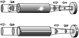
Perhaps the most commonly used photorefractive self-pumped phase conjugator type is the socalled cat conjugator [82Fei]. In this case the first pump beam is generated from the incident beam by fanning, the second pump beam by backreflection on the crystal corner. Figure 4.4.10 shows a rhodium-doped barium titanate crystal which acts as a cat conjugator for an incident beam of 5 mW
Landolt-B¨ornstein
New Series VIII/1A1
244 |
4.4.6 Photorefraction |
[Ref. p. 245 |
|||||
|
|
|
|
|
|
|
|
|
|
|
Spatial |
FP |
|
||
|
Array |
/2 |
|
||||
|
=array810 nm |
waveλ/2plate- |
filter |
etalon |
|
||
|
λ=810nm |
wave plate |
|
|
|
|
BaTiO3: Rh |
|
|
|
|
|
|||
|
|
|
|
|
|
|
|
|
|
|
|
|
|
|
Output : P = 230 mW |
|
|
|
|
|
|
|
|
|
|
|
|
|
|
|
|
|
|
|
|
|
|
|
|
|
|
|
|
|
|
|
|
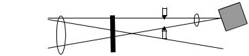
Fig. 4.4.11. Coherent diode laser array coupled by a phase-conjugating BaTiO3:Rh crystal [98Lob].
optical power at 808 nm wavelength. The formed internal phase-conjugation loops can be observed in the lower right-hand corner of the crystal. Self-pumped phase-conjugate reflectivities as high as 60–80 % have been reported for visible and near-infrared wavelengths by numerous investigators using photorefractive crystals in various arrangements [85Gue, 86Pep, 95Mu, 94Wec, 97Huo].
The e cient operation of photorefractive phase conjugators at low and moderate power levels makes this type of device attractive especially for diode-laser applications. Free-running high-power diode laser arrays emit laser beams of poor spatial and spectral quality. Optical phase-conjugate feedback can increase both the spatial and the temporal coherence of the radiation. Figure 4.4.11 shows an external-cavity diode laser system comprising a photorefractive BaTiO3 crystal as phase conjugator, a Fabry-Perot etalon, and a spatial filter forcing the laser diode array to operate in a single spatial and a single longitudinal mode [98Lob]. The coherence length of the phase-conjugate laser system has been increased by a factor of 70 and the output has become almost di ractionlimited. The output power is reduced from 440 mW to 230 mW.
Landolt-B¨ornstein
New Series VIII/1A1