

- •Using Your Sybex Electronic Book
- •Acknowledgments
- •Contents at a Glance
- •Introduction
- •Who Should Read This Book?
- •How About the Advanced Topics?
- •The Structure of the Book
- •How to Reach the Author
- •The Integrated Development Environment
- •The Start Page
- •Project Types
- •Your First VB Application
- •Making the Application More Robust
- •Making the Application More User-Friendly
- •The IDE Components
- •The IDE Menu
- •The Toolbox Window
- •The Solution Explorer
- •The Properties Window
- •The Output Window
- •The Command Window
- •The Task List Window
- •Environment Options
- •A Few Common Properties
- •A Few Common Events
- •A Few Common Methods
- •Building a Console Application
- •Summary
- •Building a Loan Calculator
- •How the Loan Application Works
- •Designing the User Interface
- •Programming the Loan Application
- •Validating the Data
- •Building a Math Calculator
- •Designing the User Interface
- •Programming the MathCalculator App
- •Adding More Features
- •Exception Handling
- •Taking the LoanCalculator to the Web
- •Working with Multiple Forms
- •Working with Multiple Projects
- •Executable Files
- •Distributing an Application
- •VB.NET at Work: Creating a Windows Installer
- •Finishing the Windows Installer
- •Running the Windows Installer
- •Verifying the Installation
- •Summary
- •Variables
- •Declaring Variables
- •Types of Variables
- •Converting Variable Types
- •User-Defined Data Types
- •Examining Variable Types
- •Why Declare Variables?
- •A Variable’s Scope
- •The Lifetime of a Variable
- •Constants
- •Arrays
- •Declaring Arrays
- •Initializing Arrays
- •Array Limits
- •Multidimensional Arrays
- •Dynamic Arrays
- •Arrays of Arrays
- •Variables as Objects
- •So, What’s an Object?
- •Formatting Numbers
- •Formatting Dates
- •Flow-Control Statements
- •Test Structures
- •Loop Structures
- •Nested Control Structures
- •The Exit Statement
- •Summary
- •Modular Coding
- •Subroutines
- •Functions
- •Arguments
- •Argument-Passing Mechanisms
- •Event-Handler Arguments
- •Passing an Unknown Number of Arguments
- •Named Arguments
- •More Types of Function Return Values
- •Overloading Functions
- •Summary
- •The Appearance of Forms
- •Properties of the Form Control
- •Placing Controls on Forms
- •Setting the TabOrder
- •VB.NET at Work: The Contacts Project
- •Anchoring and Docking
- •Loading and Showing Forms
- •The Startup Form
- •Controlling One Form from within Another
- •Forms vs. Dialog Boxes
- •VB.NET at Work: The MultipleForms Project
- •Designing Menus
- •The Menu Editor
- •Manipulating Menus at Runtime
- •Building Dynamic Forms at Runtime
- •The Form.Controls Collection
- •VB.NET at Work: The DynamicForm Project
- •Creating Event Handlers at Runtime
- •Summary
- •The TextBox Control
- •Basic Properties
- •Text-Manipulation Properties
- •Text-Selection Properties
- •Text-Selection Methods
- •Undoing Edits
- •VB.NET at Work: The TextPad Project
- •Capturing Keystrokes
- •The ListBox, CheckedListBox, and ComboBox Controls
- •Basic Properties
- •The Items Collection
- •VB.NET at Work: The ListDemo Project
- •Searching
- •The ComboBox Control
- •The ScrollBar and TrackBar Controls
- •The ScrollBar Control
- •The TrackBar Control
- •Summary
- •The Common Dialog Controls
- •Using the Common Dialog Controls
- •The Color Dialog Box
- •The Font Dialog Box
- •The Open and Save As Dialog Boxes
- •The Print Dialog Box
- •The RichTextBox Control
- •The RTF Language
- •Methods
- •Advanced Editing Features
- •Cutting and Pasting
- •Searching in a RichTextBox Control
- •Formatting URLs
- •VB.NET at Work: The RTFPad Project
- •Summary
- •What Is a Class?
- •Building the Minimal Class
- •Adding Code to the Minimal Class
- •Property Procedures
- •Customizing Default Members
- •Custom Enumerations
- •Using the SimpleClass in Other Projects
- •Firing Events
- •Shared Properties
- •Parsing a Filename String
- •Reusing the StringTools Class
- •Encapsulation and Abstraction
- •Inheritance
- •Inheriting Existing Classes
- •Polymorphism
- •The Shape Class
- •Object Constructors and Destructors
- •Instance and Shared Methods
- •Who Can Inherit What?
- •Parent Class Keywords
- •Derived Class Keyword
- •Parent Class Member Keywords
- •Derived Class Member Keyword
- •MyBase and MyClass
- •Summary
- •On Designing Windows Controls
- •Enhancing Existing Controls
- •Building the FocusedTextBox Control
- •Building Compound Controls
- •VB.NET at Work: The ColorEdit Control
- •VB.NET at Work: The Label3D Control
- •Raising Events
- •Using the Custom Control in Other Projects
- •VB.NET at Work: The Alarm Control
- •Designing Irregularly Shaped Controls
- •Designing Owner-Drawn Menus
- •Designing Owner-Drawn ListBox Controls
- •Using ActiveX Controls
- •Summary
- •Programming Word
- •Objects That Represent Text
- •The Documents Collection and the Document Object
- •Spell-Checking Documents
- •Programming Excel
- •The Worksheets Collection and the Worksheet Object
- •The Range Object
- •Using Excel as a Math Parser
- •Programming Outlook
- •Retrieving Information
- •Recursive Scanning of the Contacts Folder
- •Summary
- •Advanced Array Topics
- •Sorting Arrays
- •Searching Arrays
- •Other Array Operations
- •Array Limitations
- •The ArrayList Collection
- •Creating an ArrayList
- •Adding and Removing Items
- •The HashTable Collection
- •VB.NET at Work: The WordFrequencies Project
- •The SortedList Class
- •The IEnumerator and IComparer Interfaces
- •Enumerating Collections
- •Custom Sorting
- •Custom Sorting of a SortedList
- •The Serialization Class
- •Serializing Individual Objects
- •Serializing a Collection
- •Deserializing Objects
- •Summary
- •Handling Strings and Characters
- •The Char Class
- •The String Class
- •The StringBuilder Class
- •VB.NET at Work: The StringReversal Project
- •VB.NET at Work: The CountWords Project
- •Handling Dates
- •The DateTime Class
- •The TimeSpan Class
- •VB.NET at Work: Timing Operations
- •Summary
- •Accessing Folders and Files
- •The Directory Class
- •The File Class
- •The DirectoryInfo Class
- •The FileInfo Class
- •The Path Class
- •VB.NET at Work: The CustomExplorer Project
- •Accessing Files
- •The FileStream Object
- •The StreamWriter Object
- •The StreamReader Object
- •Sending Data to a File
- •The BinaryWriter Object
- •The BinaryReader Object
- •VB.NET at Work: The RecordSave Project
- •The FileSystemWatcher Component
- •Properties
- •Events
- •VB.NET at Work: The FileSystemWatcher Project
- •Summary
- •Displaying Images
- •The Image Object
- •Exchanging Images through the Clipboard
- •Drawing with GDI+
- •The Basic Drawing Objects
- •Drawing Shapes
- •Drawing Methods
- •Gradients
- •Coordinate Transformations
- •Specifying Transformations
- •VB.NET at Work: Plotting Functions
- •Bitmaps
- •Specifying Colors
- •Defining Colors
- •Processing Bitmaps
- •Summary
- •The Printing Objects
- •PrintDocument
- •PrintDialog
- •PageSetupDialog
- •PrintPreviewDialog
- •PrintPreviewControl
- •Printer and Page Properties
- •Page Geometry
- •Printing Examples
- •Printing Tabular Data
- •Printing Plain Text
- •Printing Bitmaps
- •Using the PrintPreviewControl
- •Summary
- •Examining the Advanced Controls
- •How Tree Structures Work
- •The ImageList Control
- •The TreeView Control
- •Adding New Items at Design Time
- •Adding New Items at Runtime
- •Assigning Images to Nodes
- •Scanning the TreeView Control
- •The ListView Control
- •The Columns Collection
- •The ListItem Object
- •The Items Collection
- •The SubItems Collection
- •Summary
- •Types of Errors
- •Design-Time Errors
- •Runtime Errors
- •Logic Errors
- •Exceptions and Structured Exception Handling
- •Studying an Exception
- •Getting a Handle on this Exception
- •Finally (!)
- •Customizing Exception Handling
- •Throwing Your Own Exceptions
- •Debugging
- •Breakpoints
- •Stepping Through
- •The Local and Watch Windows
- •Summary
- •Basic Concepts
- •Recursion in Real Life
- •A Simple Example
- •Recursion by Mistake
- •Scanning Folders Recursively
- •Describing a Recursive Procedure
- •Translating the Description to Code
- •The Stack Mechanism
- •Stack Defined
- •Recursive Programming and the Stack
- •Passing Arguments through the Stack
- •Special Issues in Recursive Programming
- •Knowing When to Use Recursive Programming
- •Summary
- •MDI Applications: The Basics
- •Building an MDI Application
- •Built-In Capabilities of MDI Applications
- •Accessing Child Forms
- •Ending an MDI Application
- •A Scrollable PictureBox
- •Summary
- •What Is a Database?
- •Relational Databases
- •Exploring the Northwind Database
- •Exploring the Pubs Database
- •Understanding Relations
- •The Server Explorer
- •Working with Tables
- •Relationships, Indices, and Constraints
- •Structured Query Language
- •Executing SQL Statements
- •Selection Queries
- •Calculated Fields
- •SQL Joins
- •Action Queries
- •The Query Builder
- •The Query Builder Interface
- •SQL at Work: Calculating Sums
- •SQL at Work: Counting Rows
- •Limiting the Selection
- •Parameterized Queries
- •Calculated Columns
- •Specifying Left, Right, and Inner Joins
- •Stored Procedures
- •Summary
- •How About XML?
- •Creating a DataSet
- •The DataGrid Control
- •Data Binding
- •VB.NET at Work: The ViewEditCustomers Project
- •Binding Complex Controls
- •Programming the DataAdapter Object
- •The Command Objects
- •The Command and DataReader Objects
- •VB.NET at Work: The DataReader Project
- •VB.NET at Work: The StoredProcedure Project
- •Summary
- •The Structure of a DataSet
- •Navigating the Tables of a DataSet
- •Updating DataSets
- •The DataForm Wizard
- •Handling Identity Fields
- •Transactions
- •Performing Update Operations
- •Updating Tables Manually
- •Building and Using Custom DataSets
- •Summary
- •An HTML Primer
- •HTML Code Elements
- •Server-Client Interaction
- •The Structure of HTML Documents
- •URLs and Hyperlinks
- •The Basic HTML Tags
- •Inserting Graphics
- •Tables
- •Forms and Controls
- •Processing Requests on the Server
- •Building a Web Application
- •Interacting with a Web Application
- •Maintaining State
- •The Web Controls
- •The ASP.NET Objects
- •The Page Object
- •The Response Object
- •The Request Object
- •The Server Object
- •Using Cookies
- •Handling Multiple Forms in Web Applications
- •Summary
- •The Data-Bound Web Controls
- •Simple Data Binding
- •Binding to DataSets
- •Is It a Grid, or a Table?
- •Getting Orders on the Web
- •The Forms of the ProductSearch Application
- •Paging Large DataSets
- •Customizing the Appearance of the DataGrid Control
- •Programming the Select Button
- •Summary
- •How to Serve the Web
- •Building a Web Service
- •Consuming the Web Service
- •Maintaining State in Web Services
- •A Data-Driven Web Service
- •Consuming the Products Web Service in VB
- •Summary
632 Chapter 14 DRAWING AND PAINTING WITH VISUAL BASIC
Drawing with GDI+
GDI stands for Graphics Design Interface, and it’s a collection of classes that enables you to create graphics, text, and images. In short, GDI is the graphics engine of Windows. GDI has been around for many years, and its latest version is GDI+, which is the only way to create graphics in .NET. All the drawing statements of VB6 are gone, and although it’s more difficult to create graphics with GDI+, the new graphics engine is faster, richer, and common for all .NET languages.
One of the basic characteristics of GDI+ is that it’s stateless. This means that a graphics operation is totally independent of the previous one and can’t affect the following one. To draw a line, you must specify a Pen object and the two endpoints of the line. You must do the same for the next line you’ll draw. You can’t assume that the second line will use the same pen, or that it will start at the point where the previous line ended. There isn’t even a default font for text-drawing methods. Every time you draw some text, you must specify the font in which the text will be rendered, as well as the Brush object that will be used to draw the text.
The GDI+ classes reside in the following namespaces, and you must import one or more of them
in your projects: System.Drawing, System.Drawing2D, System.Drawing.Imaging, and System.Draw-
ing.Text. In this chapter we’ll explore all three aspects of GDI+, namely vector drawing, imaging, and typography, starting with the basic drawing objects.
Before you start drawing, you must select the surface you want to draw on, the type of shapes you want to draw, and the instrument you’ll use to draw with. The surface on which you can draw is a Graphics object. This object exposes numerous methods for drawing basic (and not so basic) shapes. To draw on a form, or a control, we request the proper Graphics object, which exposes all the drawing methods.
The next step is to decide what instrument you’ll use to draw with. There are two major drawing instruments, the Pen object and the Brush object. You use pens to draw stroked shapes (lines, rectangles, curves) and brushes to draw filled shapes (any area enclosed by a shape). The main characteristics of the Pen object are its color and its width (the size of the trace left by the pen). The main characteristic of the Brush object is the color or pattern that will fill the shape. An interesting variation of the Brush object is the gradient brushes, which change color as you move from one point of the shape you want to fill to another. You can start filling a shape with red in the middle and specify that as you move toward the edges of the shape, the fill color fades to yellow.
After you have specified the drawing surface and the drawing instrument, you draw an actual shape by calling the appropriate method of the Graphics object. Here’s a simple example of a few statements that draw a line on the form.
Dim redPen As Pen = New Pen(Color.Red, 2)
Dim point1 As Point = New Point(10,10)
Dim point2 As Point = New Point(120,180)
Me.CreateGraphics.DrawLine(redPen, point1, point2)
The first statement declares a new Pen object, which is initialized to draw in red with a width of 2 pixels. The following two statements declare and initialize two points, which are the line’s starting and ending points. The coordinates are expressed in pixels, and the origin is at the form’s top-left corner.
The last statement draws a line by calling the DrawLine method. The expression Me.CreateGraphics retrieves the Graphics object of the form, which exposes all the drawing methods, including the DrawLine
Copyright ©2002 SYBEX, Inc., Alameda, CA |
www.sybex.com |

DRAWING WITH GDI+ 633
method. The Graphics object is the drawing surface, and all drawing methods produce some output on this surface. You can also create a new Graphics object and associate it with the form:
Dim G As Graphics
G = Me.CreateGraphics G.DrawLine(redPen, point1, point2)
The DrawLine method accepts as argument the pen it will use to draw and the line’s starting and ending points. I have used two Point objects to make the code easier to read. The DrawLine method, like all other drawing methods, is heavily overloaded. You can omit the declarations of the two points and pass their coordinates as arguments to the DrawLine method with the following statement:
Me.CreateGraphics.DrawLine(redPen, 10, 10, 120, 180)
You can also omit the declaration of a Pen object variable and initialize it in the same statement that draws the line:
Me.CreateGraphics.DrawLine(New Pen(Color.Red, 2), 10, 10, 120, 180)
All coordinates are expressed by default in pixels. It’s possible to specify coordinates in different units and let GDI+ convert them to pixels before drawing. If you’re drawing molecules, your units will be tiny fractions of a millimeter (microns), while if you’re drawing the trajectories of planets, your units will be millions or billions of miles. For now, we’ll use pixels, which are quite appropriate for simple objects. Once you’ve familiarized yourself with the drawing methods, you’ll learn how to specify different coordinate systems.
The Basic Drawing Objects
This is a good point to introduce some of the objects we’ll be using all the time in drawing. Instead of interrupting the discussion of the more interesting drawing methods that will follow, I’d rather discuss here all the auxiliary objects used in drawing. No matter what you draw, or what drawing instrument you’re using, one or more of the objects discussed in this section will be required.
The Graphics Object
The Graphics object is the drawing surface. Every control you can draw on exposes a Graphics property, which is an object. The Graphics object exposes all the methods for drawing on the surface of the control. It goes without saying that the PictureBox control exposes a Graphics property, but so does the TextBox control, as well as many controls you wouldn’t expect. It’s not recommended that you draw on a TextBox control, of course, unless you’re coding a peculiar application. Bear in mind that anything you draw on the TextBox control will disappear as you start typing. You must first place the text on the control and then draw on its surface.
To retrieve the Graphics object of a control, call the control’s CreateGraphics method. Because this method returns a Graphics object, it also exposes all the methods and properties you will use to create graphics on the control. If you enter the string Me.CreateGraphics and a period, you will see a list of the members of the Graphics object in a drop-down list. The DpiX and DpiY properties, for example, return the horizontal and vertical resolution of the form. On an average monitor, these two properties return a resolution of 96 dots per inch.
Copyright ©2002 SYBEX, Inc., Alameda, CA |
www.sybex.com |

634 Chapter 14 DRAWING AND PAINTING WITH VISUAL BASIC
To use the Graphics object, you must first import the library Drawing2D into your project with the following statement (if not, you will have to fully qualify the references to the drawing methods):
Imports System.Drawing.Drawing2D
Then, declare a variable of the Graphics type and initialize it to the Graphics object returned by the control’s CreateGraphics method:
Dim G As Graphics
G = PictureBox1.CreateGraphics
At this point you’re ready to start drawing on the PictureBox1 control with the methods we’ll discuss in the following sections. If you want to draw on the form, create a Graphics object with the form’s CreateGraphics method:
Dim G As Graphics
G = Me.CreateGraphics
You can actually draw on any control that provides a CreateGraphics method.
Note The Graphics object is initialized to the control’s drawing surface the moment you create it. If the form is resized at runtime, the Graphics object won’t change and part of the drawing surface may not be available for drawing. If you create a Graphics object to represent a form in the form’s Load event handler, this object will represent the surface of the control the moment the Graphics object was created. If the form is resized at runtime, the drawing methods you apply to the Graphics object will take effect in part of the form. The most appropriate event for initializing the Graphics object and inserting the painting code is the form’s Paint event. This event is fired when the form must be redrawn. Insert your drawing code there and create a Graphics object in the Paint event. Then draw on the Graphics object and release it when you’re done.
The Graphics object exposes the following basic properties, in addition to the drawing methods discussed in the following sections.
DpiX, DpiY The horizontal and vertical resolutions of the drawing surface. These properties are expressed in pixels per inch (or dots per inch, if the drawing surface is your printer). A distance of Graphics.DpiX pixels will be exactly one inch on the monitor. If you plan to work with a unit other than pixels, you should take advantage of the PageUnit property.
PageUnit The unit in which you want to express the coordinates on the Graphics object. Its value can be a member of the GraphicsUnit enumeration (Table 14.3).
TextRenderingHint This property specifies how the Graphics object will render text; its value is one of the members of the TextRenderingHint enumeration: AntiAlias, AntiAliasGridFit,
ClearTypeGridFit, SingleBitPerPixel, SingleBitPerPixelGridFit, and SystemDefault.
SmoothingMode This property is similar to the TextRenderingHint, but it applies to all shapes, not just text. Its value is one of the members of the SmoothingMode enumeration:
AntiAlias, Default, HighQuality, HighSpeed, Invalid, and None.
Figure 14.6 shows an ellipse drawn with the SmoothingMode property set to AntiAlias (the one on the left) and to HighSpeed (on the right). Parts of the two ellipses were blown up with an imageprocessing application, so that you can see the difference in the two modes. Anti-aliased shapes
Copyright ©2002 SYBEX, Inc., Alameda, CA |
www.sybex.com |

DRAWING WITH GDI+ 635
(or text, for that matter) are smoother because their edges contain shades between the drawing and background colors. These shades are introduced by GDI+ automatically when you render shapes to lessen the contrast between the two colors. As a result, anti-aliased drawings look smoother.
Table 14.3: The GraphicsUnit Enumeration
Value |
Description |
Display |
The unit is 1⁄75 of an inch. |
Document |
The unit is 1⁄300 of an inch. |
Inch |
The unit is one inch. |
Millimeter |
The unit is one millimeter. |
Pixel |
The unit is one pixel (the default value). |
Point |
The unit is a printer’s point (1⁄72 of an inch). |
World |
The developer specifies the unit to be used. |
|
|
Figure 14.6
SmoothingMode set to (left) AntiAlias and (right)
HighSpeed
Figure 14.7 shows the effect of the TextRenderingHint property on text. The anti-aliased text looks much better on the monitor. The ClearType setting has no effect on CRT monitors. You can see the difference only when you render text on LCD monitors, such as the new flat panel monitors or notebook monitors.
Copyright ©2002 SYBEX, Inc., Alameda, CA |
www.sybex.com |
636 Chapter 14 DRAWING AND PAINTING WITH VISUAL BASIC
Figure 14.7
TextRenderingHint set to (top)
ClearType and (bottom)
AntiAlias
The Point Object
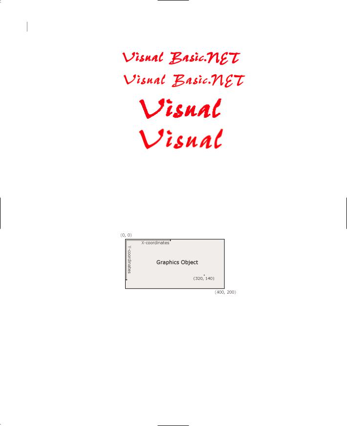
The Point object represents a point on the drawing surface and is expressed as a pair of (x, y) coordinates. The x coordinate is its horizontal distance from the origin, and the y coordinate is its vertical distance from the origin. The origin is the point with coordinates (0, 0), and this is the top-left corner of the drawing surface. Figure 14.8 shows the coordinates of the two opposite corners of the Graphics object and a point in its interior.
Figure 14.8
The origin of the default coordinate system is at the topleft corner of the drawing surface.
To create a new Point object, you must specify its x and y coordinates, represented as X and Y properties of the object. The constructor of the Point object is:
Dim P1 As Point
P1 = New Point(X, Y)
where X and Y are integer values, the point’s horizontal and vertical distances from the origin. Alternatively, you can declare a Point object and then set its X and Y properties:
Dim P1 As Point
P1.X = 34
P1.Y = 50
Copyright ©2002 SYBEX, Inc., Alameda, CA |
www.sybex.com |

DRAWING WITH GDI+ 637
As you will see later, coordinates can also be specified as Single numbers (if you choose to use a coordinate system other than pixels). In this case, use the PointF object, which is identical to the Point object with the exception that its coordinates are non-integers (F stands for floating-point, and floating-point numbers are represented by the Single or Double data type).
The Rectangle Object
Another object quite common in drawing is the Rectangle object. Its constructor accepts as arguments the coordinates of the rectangle’s top-left corner and its width and height.
Dim box As Rectangle
box = New Rectangle(X, Y, width, height)
The following statement creates a rectangle whose top-left corner is 1 pixel to the right and 1 pixel down from the origin and whose dimensions are 100 and 20 pixels:
box = New Rectangle(1, 1, 100, 20)
The box variable represents a rectangle, but it doesn’t generate any output on the monitor. If you want to draw the rectangle, you can pass it as argument to the DrawRectangle or FillRectangle method, depending on whether you want to draw the outline of the rectangle or a filled rectangle.
Another form of the Rectangle constructor uses the Size object to specify the dimensions of the rectangle:
box = New Rectangle(point, size)
To create the same Rectangle object as in the last example with this form of the constructor, use the following statement:
Dim P As Point P.X = 1
P.Y = 1
Dim S As Size
S.Width = 100
S.Height = 20
box = New Rectangle(P, S)
Both sets of statements create a rectangle that extends from point (1, 1) to the point ([1 + 100], [1 + 20]) or (101, 21), in the same manner as the ones shown in Figure 14.9.
Figure 14.9
Specifying rectangles with the coordinates of their top left corner and their dimensions
Copyright ©2002 SYBEX, Inc., Alameda, CA |
www.sybex.com |

638 Chapter 14 DRAWING AND PAINTING WITH VISUAL BASIC
Alternatively, you can declare a Rectangle object and then set its properties, as shown here:
Dim box As new Rectangle box.X = 1
box.Y = 1 box.Width = 100 box.Height = 20
The Color Object
The Color object represents a color, and there are many ways to specify a color. We’ll discuss the Color object in more detail later in this chapter, in the discussion of bitmaps. In the meantime, you can specify colors by name. Declare a variable of the Color type, and initialize it to one of the named colors exposed by the Color object:
Dim myColor As Color myColor = Color.Azure
The 128 named members of the Color object will appear in a drop-down list as soon as you enter the period following the keyword Color. You can also use the FromARGB method, which creates a new color from its basic color components (the Red, Green, and Blue components). For more information on specifying colors with this method, see the section “Specifying Colors” later in this chapter.
The Color object is used to set the color of the Pen object you draw with or the color in which a string will be rendered. You can also use the same object to assign values to any color-related property, such as the BackColor property of any control. To set the background color of a TextBox control, use the following statement:
TextBox1.BackColor = Color.Beige
The Font Object
The Font object represents the font to be used when rendering strings with the DrawString method. To specify a font, you must create a new Font object, set its family name, size, and style, and then pass it as argument to the DrawString method. Alternatively, you can prompt the user for a font with the Font common dialog box and use the object returned by the dialog box’s Font property as argument with the DrawString method.
To create a new Font object, use a few statements like the following:
Dim drawFont As New Font(“Comic Sans MS”, FontStyle.Bold)
The Font constructor has 13 forms in all. Two of the simpler forms of the constructor, which allow you specify the size and the style of the font, are shown next:
Dim drawFont As New Font(name, size)
Dim drawFont As New Font(name, size, style)
where size is an integer and style is a member of the FontStyle enumeration (Bold, Italic, Regular, Strikeout, and Underline). To specify multiple styles, combine them with the Or operator:
FontStyle.Bold Or FontStyle.Italic
Copyright ©2002 SYBEX, Inc., Alameda, CA |
www.sybex.com |

DRAWING WITH GDI+ 639
You can also initialize a Font variable to an existing font. The following statement creates a Font object and initializes it to the current font of the form:
Dim textFont As New Font textFont = Me.Font
The Font object provides the Size, Bold, and Italic properties. Unfortunately, these properties are read-only and return the attributes of the font in use. You can’t turn on the bold attribute by setting the Font.Bold property to True. It would be very convenient to be able to quickly adjust the properties of an existing font and create a new one, but this isn’t the case.
Of course, you can use the current settings of an existing font to create a new Font object. The following statements build a new Font object based on the settings of the form’s current font. The new font belongs to the same family as the form’s current font, is twice the size of this font, and has the same attributes as the form’s font plus the bold attribute.
Dim textFont As Font
textFont = New Font(Me.Font.FontFamily, 2 * Me.Font.Size, _ Me.Font.Style Or FontStyle.Bold)
The Pen Object
The Pen object represents a virtual pen, which you use to draw on the Graphics object’s surface. To construct a Pen object, you must specify a color and the pen’s width in pixels. The following statements declare three Pen objects with the same color and different widths:
Dim thinPen, mediumPem, thickPen As Pen thinPen = New Pen(Color.Black, 1) mediumPen = New Pen(Color.Black, 3) thickPen = New Pen(Color.Black, 5)
If you omit the second argument, a pen with a width of a single pixel will be created by default. Another form of the Pen object’s constructor allows you to specify a brush, instead of a color:
Dim patternPen as Pen
patternPen = New Pen(brush, width)
where brush is a Brush object (which is discussed later in this chapter). As you will see, the drawing methods generate two types of drawings: stroked shapes and filled shapes. Stroked shapes (or outlines) are drawn with a pen, while filled shapes are drawn with a brush. To draw the outline of a shape with a pattern, you must create a Pen object based on an existing brush, and then use it with a drawing method.
The quickest method of creating a new Pen object is to use the built-in Pens collection, which creates a Pen with a width of one pixel and the color you specify. The following statement can appear anywhere a Pen object is required and will draw shapes in blue color:
Pens.Blue
Note There’s an important distinction between Pens and Brushes you should bear in mind as you draw with VB.NET. You can’t draw a shape with a Brush object, and you can’t fill a closed shape with a Pen. It is possible, however, to draw a shape with a pattern, as long as you assign the pattern to the Pen object. Likewise, you can fill a shape with a solid color, as long as you set the color of the Brush object you’re using to fill with.
Copyright ©2002 SYBEX, Inc., Alameda, CA |
www.sybex.com |

640 Chapter 14 DRAWING AND PAINTING WITH VISUAL BASIC
The Pen object exposes these properties:
LineJoin Determines how two consecutive line segments will be joined. Its value is one of the members of the LineJoin enumeration: Bevel, Miter, MiterClipped, and Round.
StartCap, EndCap Determine the caps at the beginning and end of a line segment respectively. Their value is one of the members of the LineCap enumeration: Round, Square, Flat, Diamond, and so on.
DashCap Determines the cap to be used at the beginning and end of a dashed line. Its value is one of the members of the DashCap enumeration: Flat, Round, and Triangle.
DashStyle Determines the style of the dashed lines drawn with the specific Pen. Its value is one of the members of the DashStyle enumeration (Solid, Dash, DashDot, DashDotDot, Dot, and Custom)
PenType Determines the style of the Pen. Its value is one of the members of the PenType
enumeration: HatchFilled, LinearGradient, PathGradient, SolidColor, and TextureFill.
The Path Object
The Path object is a combination of the various drawing entities, like lines, rectangles, and curves. You can create as many of these drawing entities and build a new entity, which is called Path. Paths are usually closed and filled with a color, a gradient or a bitmap. You can create a path in several ways. The simplest method is to create a new Path object and then use one of these methods to append the appropriate item to the path:
AddArc |
AddEllipse |
AddPolygon |
AddBezier |
AddLine |
AddRectangle |
AddCurve |
AddPie |
AddString |
These methods add to the path the same shapes you can draw on the Graphics object with the methods discussed in the later section “Drawing Shapes with the Graphics Object.” There’s even an AddPath method, which adds an existing path to the current one. The syntax of the various methods that add shapes to a path is identical to the corresponding methods that draw. We simply omit the first argument (the Pen object), because all the shapes will be rendered with the same pen. The following method draws an ellipse:
Me.CreateGraphics.DrawEllipse(pen, 10, 30, 40, 50)
To add the same ellipse to a Path object, use the following statement:
Dim myPath As New Path myPath.AddEllipse(10, 30, 40, 50)
To display the path, call the DrawPath method passing a Pen and the Path object as arguments:
Me.CreateGraphics.DrawPath(myPen, myPath)
Copyright ©2002 SYBEX, Inc., Alameda, CA |
www.sybex.com |

DRAWING WITH GDI+ 641
Why combine shapes into paths instead of drawing individual shapes? There are many reasons for maintaining multiple shapes as a single entity. Once the shape has been defined, you can draw multiple instances of it on the monitor, draw the same path with a different pen, or fill the path’s constituent shapes with the same bitmap or gradient. Paths are also used to create the ultimate type of gradient, the PathGradient, as you will see in the section “Path Gradients,” later in this chapter.
Later in this chapter, we’ll build an application for plotting functions. To plot a function, we’ll create a shape with all the points along the curve and draw it with a single call the DrawPath method.
The Brush Object
The Brush object is the instrument for filling shapes, and you can create brushes that fill with a solid color, a pattern, or a bitmap. In reality, there’s no Brush object. The Brush class is actually an abstract class that is inherited by all the objects that implement a brush, but you can’t declare a variable of the Brush type in your code. The brush objects are:
Brush Object Type |
Fills Shapes With |
SolidBrush |
A solid color |
HatchBrush |
A hatched pattern |
LinearGradientBrush |
A linear gradient |
PathGradientBrush |
A gradient that has one starting color and many ending colors |
TextureBrush |
A bitmap |
Solid Brushes
To fill a shape with a solid color, you must create a SolidBrush object with the following constructor:
Dim sBrush As SolidBrush
sBrush = New SolidBrush(brushColor)
where brushColor is a color value, specified with the help of the Color object. Every filled object you draw with the sBrush object will be filled with the color of the brush.
Hatched Brushes
To fill a shape with a hatch pattern, you must create a HatchBrush object with the following constructor:
Dim hBrush As HatchBrush
HBrush = New HatchBrush(hatchStyle, hatchColor, backColor)
The first argument is the style of the hatch, and it can have one of the values shown in Table 14.4. The other two arguments are the colors to be used in the hatch. The hatch is a pattern of lines drawn on a background, and the two color arguments are the color of the hatch lines and the color of the background on which the hatch is drawn.
Copyright ©2002 SYBEX, Inc., Alameda, CA |
www.sybex.com |