

- •Using Your Sybex Electronic Book
- •Acknowledgments
- •Contents at a Glance
- •Introduction
- •Who Should Read This Book?
- •How About the Advanced Topics?
- •The Structure of the Book
- •How to Reach the Author
- •The Integrated Development Environment
- •The Start Page
- •Project Types
- •Your First VB Application
- •Making the Application More Robust
- •Making the Application More User-Friendly
- •The IDE Components
- •The IDE Menu
- •The Toolbox Window
- •The Solution Explorer
- •The Properties Window
- •The Output Window
- •The Command Window
- •The Task List Window
- •Environment Options
- •A Few Common Properties
- •A Few Common Events
- •A Few Common Methods
- •Building a Console Application
- •Summary
- •Building a Loan Calculator
- •How the Loan Application Works
- •Designing the User Interface
- •Programming the Loan Application
- •Validating the Data
- •Building a Math Calculator
- •Designing the User Interface
- •Programming the MathCalculator App
- •Adding More Features
- •Exception Handling
- •Taking the LoanCalculator to the Web
- •Working with Multiple Forms
- •Working with Multiple Projects
- •Executable Files
- •Distributing an Application
- •VB.NET at Work: Creating a Windows Installer
- •Finishing the Windows Installer
- •Running the Windows Installer
- •Verifying the Installation
- •Summary
- •Variables
- •Declaring Variables
- •Types of Variables
- •Converting Variable Types
- •User-Defined Data Types
- •Examining Variable Types
- •Why Declare Variables?
- •A Variable’s Scope
- •The Lifetime of a Variable
- •Constants
- •Arrays
- •Declaring Arrays
- •Initializing Arrays
- •Array Limits
- •Multidimensional Arrays
- •Dynamic Arrays
- •Arrays of Arrays
- •Variables as Objects
- •So, What’s an Object?
- •Formatting Numbers
- •Formatting Dates
- •Flow-Control Statements
- •Test Structures
- •Loop Structures
- •Nested Control Structures
- •The Exit Statement
- •Summary
- •Modular Coding
- •Subroutines
- •Functions
- •Arguments
- •Argument-Passing Mechanisms
- •Event-Handler Arguments
- •Passing an Unknown Number of Arguments
- •Named Arguments
- •More Types of Function Return Values
- •Overloading Functions
- •Summary
- •The Appearance of Forms
- •Properties of the Form Control
- •Placing Controls on Forms
- •Setting the TabOrder
- •VB.NET at Work: The Contacts Project
- •Anchoring and Docking
- •Loading and Showing Forms
- •The Startup Form
- •Controlling One Form from within Another
- •Forms vs. Dialog Boxes
- •VB.NET at Work: The MultipleForms Project
- •Designing Menus
- •The Menu Editor
- •Manipulating Menus at Runtime
- •Building Dynamic Forms at Runtime
- •The Form.Controls Collection
- •VB.NET at Work: The DynamicForm Project
- •Creating Event Handlers at Runtime
- •Summary
- •The TextBox Control
- •Basic Properties
- •Text-Manipulation Properties
- •Text-Selection Properties
- •Text-Selection Methods
- •Undoing Edits
- •VB.NET at Work: The TextPad Project
- •Capturing Keystrokes
- •The ListBox, CheckedListBox, and ComboBox Controls
- •Basic Properties
- •The Items Collection
- •VB.NET at Work: The ListDemo Project
- •Searching
- •The ComboBox Control
- •The ScrollBar and TrackBar Controls
- •The ScrollBar Control
- •The TrackBar Control
- •Summary
- •The Common Dialog Controls
- •Using the Common Dialog Controls
- •The Color Dialog Box
- •The Font Dialog Box
- •The Open and Save As Dialog Boxes
- •The Print Dialog Box
- •The RichTextBox Control
- •The RTF Language
- •Methods
- •Advanced Editing Features
- •Cutting and Pasting
- •Searching in a RichTextBox Control
- •Formatting URLs
- •VB.NET at Work: The RTFPad Project
- •Summary
- •What Is a Class?
- •Building the Minimal Class
- •Adding Code to the Minimal Class
- •Property Procedures
- •Customizing Default Members
- •Custom Enumerations
- •Using the SimpleClass in Other Projects
- •Firing Events
- •Shared Properties
- •Parsing a Filename String
- •Reusing the StringTools Class
- •Encapsulation and Abstraction
- •Inheritance
- •Inheriting Existing Classes
- •Polymorphism
- •The Shape Class
- •Object Constructors and Destructors
- •Instance and Shared Methods
- •Who Can Inherit What?
- •Parent Class Keywords
- •Derived Class Keyword
- •Parent Class Member Keywords
- •Derived Class Member Keyword
- •MyBase and MyClass
- •Summary
- •On Designing Windows Controls
- •Enhancing Existing Controls
- •Building the FocusedTextBox Control
- •Building Compound Controls
- •VB.NET at Work: The ColorEdit Control
- •VB.NET at Work: The Label3D Control
- •Raising Events
- •Using the Custom Control in Other Projects
- •VB.NET at Work: The Alarm Control
- •Designing Irregularly Shaped Controls
- •Designing Owner-Drawn Menus
- •Designing Owner-Drawn ListBox Controls
- •Using ActiveX Controls
- •Summary
- •Programming Word
- •Objects That Represent Text
- •The Documents Collection and the Document Object
- •Spell-Checking Documents
- •Programming Excel
- •The Worksheets Collection and the Worksheet Object
- •The Range Object
- •Using Excel as a Math Parser
- •Programming Outlook
- •Retrieving Information
- •Recursive Scanning of the Contacts Folder
- •Summary
- •Advanced Array Topics
- •Sorting Arrays
- •Searching Arrays
- •Other Array Operations
- •Array Limitations
- •The ArrayList Collection
- •Creating an ArrayList
- •Adding and Removing Items
- •The HashTable Collection
- •VB.NET at Work: The WordFrequencies Project
- •The SortedList Class
- •The IEnumerator and IComparer Interfaces
- •Enumerating Collections
- •Custom Sorting
- •Custom Sorting of a SortedList
- •The Serialization Class
- •Serializing Individual Objects
- •Serializing a Collection
- •Deserializing Objects
- •Summary
- •Handling Strings and Characters
- •The Char Class
- •The String Class
- •The StringBuilder Class
- •VB.NET at Work: The StringReversal Project
- •VB.NET at Work: The CountWords Project
- •Handling Dates
- •The DateTime Class
- •The TimeSpan Class
- •VB.NET at Work: Timing Operations
- •Summary
- •Accessing Folders and Files
- •The Directory Class
- •The File Class
- •The DirectoryInfo Class
- •The FileInfo Class
- •The Path Class
- •VB.NET at Work: The CustomExplorer Project
- •Accessing Files
- •The FileStream Object
- •The StreamWriter Object
- •The StreamReader Object
- •Sending Data to a File
- •The BinaryWriter Object
- •The BinaryReader Object
- •VB.NET at Work: The RecordSave Project
- •The FileSystemWatcher Component
- •Properties
- •Events
- •VB.NET at Work: The FileSystemWatcher Project
- •Summary
- •Displaying Images
- •The Image Object
- •Exchanging Images through the Clipboard
- •Drawing with GDI+
- •The Basic Drawing Objects
- •Drawing Shapes
- •Drawing Methods
- •Gradients
- •Coordinate Transformations
- •Specifying Transformations
- •VB.NET at Work: Plotting Functions
- •Bitmaps
- •Specifying Colors
- •Defining Colors
- •Processing Bitmaps
- •Summary
- •The Printing Objects
- •PrintDocument
- •PrintDialog
- •PageSetupDialog
- •PrintPreviewDialog
- •PrintPreviewControl
- •Printer and Page Properties
- •Page Geometry
- •Printing Examples
- •Printing Tabular Data
- •Printing Plain Text
- •Printing Bitmaps
- •Using the PrintPreviewControl
- •Summary
- •Examining the Advanced Controls
- •How Tree Structures Work
- •The ImageList Control
- •The TreeView Control
- •Adding New Items at Design Time
- •Adding New Items at Runtime
- •Assigning Images to Nodes
- •Scanning the TreeView Control
- •The ListView Control
- •The Columns Collection
- •The ListItem Object
- •The Items Collection
- •The SubItems Collection
- •Summary
- •Types of Errors
- •Design-Time Errors
- •Runtime Errors
- •Logic Errors
- •Exceptions and Structured Exception Handling
- •Studying an Exception
- •Getting a Handle on this Exception
- •Finally (!)
- •Customizing Exception Handling
- •Throwing Your Own Exceptions
- •Debugging
- •Breakpoints
- •Stepping Through
- •The Local and Watch Windows
- •Summary
- •Basic Concepts
- •Recursion in Real Life
- •A Simple Example
- •Recursion by Mistake
- •Scanning Folders Recursively
- •Describing a Recursive Procedure
- •Translating the Description to Code
- •The Stack Mechanism
- •Stack Defined
- •Recursive Programming and the Stack
- •Passing Arguments through the Stack
- •Special Issues in Recursive Programming
- •Knowing When to Use Recursive Programming
- •Summary
- •MDI Applications: The Basics
- •Building an MDI Application
- •Built-In Capabilities of MDI Applications
- •Accessing Child Forms
- •Ending an MDI Application
- •A Scrollable PictureBox
- •Summary
- •What Is a Database?
- •Relational Databases
- •Exploring the Northwind Database
- •Exploring the Pubs Database
- •Understanding Relations
- •The Server Explorer
- •Working with Tables
- •Relationships, Indices, and Constraints
- •Structured Query Language
- •Executing SQL Statements
- •Selection Queries
- •Calculated Fields
- •SQL Joins
- •Action Queries
- •The Query Builder
- •The Query Builder Interface
- •SQL at Work: Calculating Sums
- •SQL at Work: Counting Rows
- •Limiting the Selection
- •Parameterized Queries
- •Calculated Columns
- •Specifying Left, Right, and Inner Joins
- •Stored Procedures
- •Summary
- •How About XML?
- •Creating a DataSet
- •The DataGrid Control
- •Data Binding
- •VB.NET at Work: The ViewEditCustomers Project
- •Binding Complex Controls
- •Programming the DataAdapter Object
- •The Command Objects
- •The Command and DataReader Objects
- •VB.NET at Work: The DataReader Project
- •VB.NET at Work: The StoredProcedure Project
- •Summary
- •The Structure of a DataSet
- •Navigating the Tables of a DataSet
- •Updating DataSets
- •The DataForm Wizard
- •Handling Identity Fields
- •Transactions
- •Performing Update Operations
- •Updating Tables Manually
- •Building and Using Custom DataSets
- •Summary
- •An HTML Primer
- •HTML Code Elements
- •Server-Client Interaction
- •The Structure of HTML Documents
- •URLs and Hyperlinks
- •The Basic HTML Tags
- •Inserting Graphics
- •Tables
- •Forms and Controls
- •Processing Requests on the Server
- •Building a Web Application
- •Interacting with a Web Application
- •Maintaining State
- •The Web Controls
- •The ASP.NET Objects
- •The Page Object
- •The Response Object
- •The Request Object
- •The Server Object
- •Using Cookies
- •Handling Multiple Forms in Web Applications
- •Summary
- •The Data-Bound Web Controls
- •Simple Data Binding
- •Binding to DataSets
- •Is It a Grid, or a Table?
- •Getting Orders on the Web
- •The Forms of the ProductSearch Application
- •Paging Large DataSets
- •Customizing the Appearance of the DataGrid Control
- •Programming the Select Button
- •Summary
- •How to Serve the Web
- •Building a Web Service
- •Consuming the Web Service
- •Maintaining State in Web Services
- •A Data-Driven Web Service
- •Consuming the Products Web Service in VB
- •Summary

DRAWING WITH GDI+ 661
where the colorChannel argument can have one of the following values: ColorChannelC (cyan channel), ColorChannelM (magenta channel), ColorChannelY (yellow channel), ColorChannelK (black channel), and ColorChannelLast (the same channel as in the last time you called the method). The four channels produced by the SetOutputChannel method are monochrome (grayscale), and each one is printed with a different ink. All four channels, however, are printed on the same page, and the result is the original image’s colors.
Gradients
In this section we’ll look at the tools for creating gradients. The techniques for gradients can get quite complicated, but I will limit the discussion to the types of gradients you’ll need for business or simple graphics applications.
Linear Gradients
Let’s start with linear gradients. Like all other gradients, they’re part of the System.Drawing class and are implemented as brushes. To use a gradient, you must create the appropriate brush with the appropriate constructor. To draw a linear gradient, you must create a LinearGradientBrush with a statement like
Dim lgBrush As LinearGradientBrush
lgBrush = New LinearGradientBrush(rect, startColor, endColor, gradientMode)
To understand how to use the arguments, you must understand how the linear gradient works. This method creates a gradient that fills a rectangle, specified by the rect object passed as the first argument. This rectangle isn’t filled with any gradient; it simply tells the method how long (or how tall) the gradient should be. The gradient starts with the startColor at the left side of the rectangle and ends with the endColor at the opposite side. The gradient changes color slowly as it moves from one end to the other. The last argument, gradientMode, specifies the direction of the gradient and can have one of the values shown in Table 14.6.
Table 14.6: The Gradient’s Mode
Value |
Effect |
BackwardDiagonal |
The gradient fills the rectangle diagonally, from the top-right corner (startColor) to |
|
the bottom-left corner (endColor). |
ForwardDiagonal |
The gradient fills the rectangle diagonally, from the top-left corner (startColor) to |
|
the bottom-right corner (endColor). |
Horizontal |
The gradient fills the rectangle from left (startColor) to right (endColor). |
Vertical |
The gradient fills the rectangle from top (startColor) to bottom (endColor). |
|
|
Copyright ©2002 SYBEX, Inc., Alameda, CA |
www.sybex.com |
662 Chapter 14 DRAWING AND PAINTING WITH VISUAL BASIC
Notice that in the descriptions of the various modes, I stated that the gradient fills the rectangle, not the shape. The gradient is calculated according to the dimensions of the rectangle specified with the first argument. If the actual shape is smaller than this rectangle, only a section of the gradient will be used to fill the shape. If the shape is larger than this rectangle, the gradient will repeat as many times as necessary to fill the shape.
Let’s say you want to use the same gradient that extends 300 pixels horizontally to fill two rectangles, one that’s 200 pixels wide and another one that’s 600 pixels wide. We’ll fill this shape with two similar LinearGradientBrushes that differ only in the size of the rectangle specified with the first argument. The first brush will use a rectangle 200 pixels wide, filled with two thirds of the gradient; the second will use a rectangle 600 pixels wide and be filled with a gradient that’s repeated twice. The code in Listing 14.17 corresponds to the GDIPlusGradients projects on the CD.
Listing 14.17: Filling Rectangles with a Linear Gradient
Private Sub LinearGradient_Click(ByVal sender As System.Object, _
ByVal e As System.EventArgs) Handles bttnLinearGradient.Click Dim G As Graphics
G = Me.CreateGraphics
Dim R As New RectangleF(20, 20, 300, 100) Dim startColor As Color = Color.BlueViolet Dim EndColor As Color = Color.LightYellow
Dim LGBrush As New System.Drawing.Drawing2D.LinearGradientBrush _
(R, startColor, EndColor, LinearGradientMode.Horizontal) G.FillRectangle(LGBrush, New Rectangle(20, 20, 200, 100)) G.FillRectangle(LGBrush, New Rectangle(20, 150, 600, 100))
End Sub
For a horizontal gradient, only the width of the rectangle is used; the height is irrelevant. For a vertical gradient, only the height of the rectangle matters. When you draw a diagonal gradient, then both dimensions are taken into consideration.
You can also use a LinearGradientBrush to fill any shape, including closed polygons and closed curves. How does the brush handle irregular shapes? It doesn’t, really. It fills, with the specified gradient, a rectangle that completely encloses the shape, and it shows only the pixels that fall within the shape. It’s like building a larger gradient and looking at it through an irregularly shaped (nonrectangular) window.
You can create gradients at any direction by setting the gradientMode argument of the LinearGradientBrush object’s constructor. The Diagonal Linear Gradient button on the GDIPlusGradients project does exactly that.
The button Gradient Text on the form of the GDIPlusGradients project on the CD renders some text with a linear gradient. As you recall from our discussion of the DrawString method, strings are rendered with a Brush object, not a Pen object. If you specify a LinearGradientBrush object, the text will be rendered with a linear gradient. The text shown in Figure 14.17 was produced by the Gradient Text button, whose code is shown in Listing 14.18.
Copyright ©2002 SYBEX, Inc., Alameda, CA |
www.sybex.com |

DRAWING WITH GDI+ 663
Figure 14.17
Drawing a string filled with a gradient
Listing 14.18: Rendering Strings with a Linear Gradient
Private Sub bttnGradientText_Click(ByVal sender As System.Object, _
ByVal e As System.EventArgs) Handles bttnGradientText.Click Dim G As Graphics
G = Me.CreateGraphics
G.Clear (me.BackColor)
G.TextRenderingHint = System.Drawing.Text.TextRenderingHint.AntiAlias Dim largeFont As New Font(“Comic Sans MS”, 48, _
FontStyle.Bold, GraphicsUnit.Point) Dim gradientStart As New PointF(0, 0)
Dim txt As String = “Gradient Text” Dim txtSize As New SizeF()
txtSize = G.MeasureString(txt, largeFont) Dim gradientEnd As New PointF() gradientEnd.X = txtSize.Width gradientEnd.Y = txtSize.Height
Dim grBrush As New LinearGradientBrush(gradientStart, gradientEnd, _ Color.Yellow, Color.Blue)
G.DrawString(txt, largeFont, grBrush, 20, 20) End Sub
The code of Listing 14.18 is a little longer than it could be (or than you might expect). Because linear gradients have a fixed size and don’t expand or shrink to fill the shape, you must call the MeasureString method to calculate the width of the string and then create a linear gradient with the exact same width. This way, the characters will be filled exactly with the specified gradient.
Path Gradients
This is the ultimate gradient tool. Using a PathGradientBrush, you can create a gradient that starts at a single point and fades into multiple different colors in different directions. You can fill a rectangle
Copyright ©2002 SYBEX, Inc., Alameda, CA |
www.sybex.com |
664 Chapter 14 DRAWING AND PAINTING WITH VISUAL BASIC
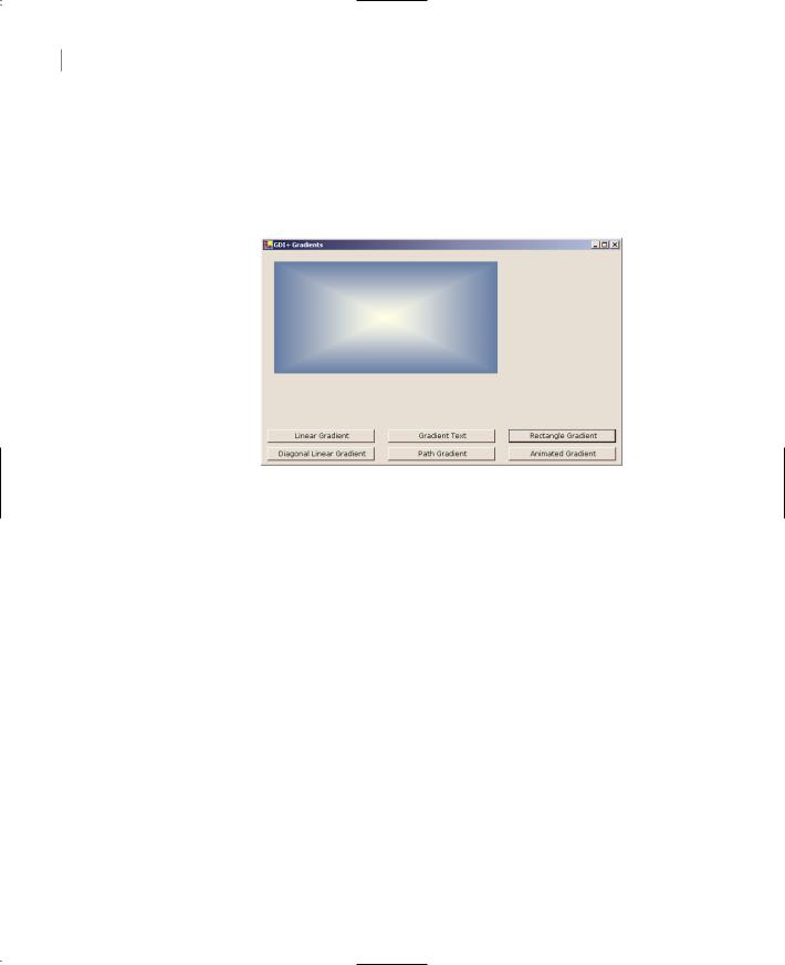
starting from a point in the interior of the rectangle, which is colored, say, black. Each corner of the rectangle may have a different ending color. The PathGradientBrush will change color in the interior of the shape and will generate a gradient that’s smooth in all directions. Figure 14.18 shows a rectangle filled with a path gradient, but the gray shades on the printed page won’t show the full impact of the gradient. Open GDIPlusGradients project on the CD to see the same figure in color (button Path Gradient).
Figure 14.18
A path gradient starting at the middle of the rectangle
To fill a shape with a path gradient, you must first create a path object. The PathBrush will be created for the specific path and can be used to fill this path—but not any other shape. Actually, you can fill any other shape with the PathBrush created for a specific path, but the gradient won’t fit the new shape. A path gradient must be applied only to the Path object for which it was created. To create a PathGradientBrush, use the following syntax:
Dim pgBrush As PathGradientBrush pgBrush = New LinearGradientBrush(path)
where path is a properly initialized Path object.
The pgBrush object provides properties that determine the exact coloring of the gradient. First, you must specify color of the gradient at the center of the shape, using the CenterColor property. The SurroundColors property is an array, with as many elements as there are vertices (corners) in the Path object. Each element of the SurroundColors array must be set to a color value, and the resulting gradient will have the color of the equivalent element of the SurroundColors array.
The following declaration creates an array of three different colors and assigns them to the SurroundColors property of a PathGradientBrush:
Dim Colors() As Color = {Color.Yellow, Color.Green, Color.Blue} pgBrush.SurroundColors = Colors
After setting the PathGradientBrush, you can fill the corresponding Path object by calling the FillPath method. The Path Gradient button on the form of GDIPlusGradient creates a rectangle filled with a gradient that’s red in the middle of the rectangle and has a different color at each corner. Listing 14.19 shows the code behind the Path Gradient button.
Copyright ©2002 SYBEX, Inc., Alameda, CA |
www.sybex.com |

DRAWING WITH GDI+ 665
Listing 14.19: Filling a Rectangle with a Path Gradient
Private Sub bttnPathGradient_Click(ByVal sender As System.Object, _
ByVal e As System.EventArgs) Handles bttnPathGradient.Click Dim G As Graphics
G = Me.CreateGraphics
Dim path As New System.Drawing.Drawing2D.GraphicsPath() path.AddLine(New Point(10, 10), New Point(400, 10)) path.AddLine(New Point(400, 10), New Point(400, 250)) path.AddLine(New Point(400, 250), New Point(10, 250))
Dim pathBrush As New System.Drawing.Drawing2D.PathGradientBrush(path) pathBrush.CenterColor = Color.Red
Dim surroundColors() As Color = _
{Color.Yellow, Color.Green, Color.Blue, Color.Cyan} pathBrush.SurroundColors = surroundColors
G.FillPath(pathBrush, path) End Sub
The gradient’s center point is, by default, the center of the shape. You can also specify the center of the gradient (the point that will be colored according to the CenterColor property). You can place the center point of the gradient anywhere by setting its CenterPoint property to a Point or PointF value.
The GDIPlusGradients application has a few more buttons that create interesting gradients, which you can examine on your own. The Rectangle Gradient button fills a rectangle with a gradient that has a single ending color all around. All the elements of the SurroundColors property are set to the same color. The Animated Gradient animates the same gradient by changing the coordinates of the PathGradientBrush object’s CenterPoint property.
Clipping
Anyone who has used drawing or image-processing applications already knows that many of the tools of a similar application make use of masks. A mask is any shape that limits the area in which you can draw. If you want to place a star or heart on an image and print something in it, you create the shape in which you want to limit your drawing tools, then convert this shape into a mask. When you draw with the mask, you can start and end your strokes anywhere on the image. Your actions will have no effect outside the mask, however.
The mask of the various image-processing applications is a clipping region. A clipping region can be anything, as long as it’s a closed shape. While the clipping region is activated, drawing takes place in the area of the clipping region. To specify a clipping area, you must call the SetClip method of the Graphics object. The SetClip method accepts the clipping area as argument, and the clipping area can be the Graphics object itself (no clipping), a Rectangle, a Path, or a Region.
Note A Region is a structure made up of simple shapes. There many methods to create a Region object—you can combine and intersect shapes, or exclude shapes from a region—but we aren’t going to discuss the Region object in this chapter, because it’s not among the common objects we use to generate the type of graphics discussed in the context of this book.
Copyright ©2002 SYBEX, Inc., Alameda, CA |
www.sybex.com |

666 Chapter 14 DRAWING AND PAINTING WITH VISUAL BASIC
The SetClip method has the following forms:
Graphics.SetClip(Graphics)
Graphics.SetClip(Rectangle)
Graphics.SetClip(GraphicsPath)
Graphics.SetClip(Region)
All methods accept a second optional argument, which determines how the new clipping area will be combined with the existing one. The second argument is the combineMode argument, and its value can be one of the members of the CombineMode enumeration: Complement, Exclude, Intersect,
Replace, Union, and XOR.
Once a clipping area has been set for the Graphics object, drawing is limited to that area. You can specify any coordinates, but only the part of the drawing that falls inside the clipping area is visible. The Clipping project demonstrates how to clip text and images within an elliptical area (see Figure 14.19). The button Boxed Text draws a string in a rectangle. The button Clipped Text draws the same text but first applies a clipping area. The clipping area is an ellipse. The Clipped Image button uses the same rectangle to clip an image. Since there’s no form of the SetClip method that accepts an ellipse as argument, we must construct a Path object, add the ellipse to the path, and then create a clipping area based on the path.
Figure 14.19
Clipping text and images in an ellipse
The following statements create the clipping area for the text, which is an ellipse. The path is created by calling the AddEllipse method of the GraphicsPath object. This path is then passed as argument to the Graphics object’s SetClip method:
Dim P As New System.Drawing.Drawing2D.GraphicsPath()
Dim clipRect As New RectangleF(30, 30, 250, 150)
P.AddEllipse(clipRect)
Dim G As Graphics
G = PictureBox1.CreateGraphics
G.SetClip(P)
The listing behind the Clipped Text and Clipped Image buttons is shown next. The first button prints some text in a rectangular area that is centered over the clipping area. The first button, Boxed Text, shows how the text is printed within the rectangle. The same rectangle and its text are then
Copyright ©2002 SYBEX, Inc., Alameda, CA |
www.sybex.com |

DRAWING WITH GDI+ 667
printed at a different location, right behind the clipping area. Both the rectangle and the ellipse are based on the same Rectangle object. Listing 14.20 shows the code behind the Boxed Text and the Clipped Text buttons.
Listing 14.20: The Boxed Text and Clipped Text Buttons
Private Sub bttnBoxedText_Click(ByVal sender As System.Object, _
ByVal e As System.EventArgs) Handles bttnBoxedText.Click Dim Rect As New RectangleF(30, 30, 250, 150)
Dim G As Graphics
G = PictureBox1.CreateGraphics
Dim format As StringFormat = New StringFormat() format.Alignment = StringAlignment.Center
G.DrawString(txt & txt, New Font(“Verdana”, 11, FontStyle.Regular), _ Brushes.Coral, Rect, format)
End Sub
Private Sub bttnClippedText_Click(ByVal sender As System.Object, _
ByVal e As System.EventArgs) Handles bttnClippedText.Click Dim P As New System.Drawing.Drawing2D.GraphicsPath()
Dim clipRect As New RectangleF(30, 30, 250, 150) P.AddEllipse(clipRect)
Dim G As Graphics
G = PictureBox1.CreateGraphics G.DrawEllipse(Pens.Red, clipRect) G.SetClip(P)
Dim format As StringFormat = New StringFormat() format.Alignment = StringAlignment.Center
G.DrawString(txt & txt, New Font(“Verdana”, 11, FontStyle.Regular), _ Brushes.Coral, clipRect, format)
End Sub
The difference between the two subroutines is that the second sets an ellipse as the clipping area and draws the same ellipse. Because the Graphics object has a clipping area, anything we draw on it is automatically clipped.
The Clipped Image button sets up a similar clipping area and then draws an image centered behind the clipping ellipse. As you saw in Figure 14.19, only the segment of the image that’s inside the clipping area is visible. The code behind the Clipped Image button is shown in Listing 14.21.
Listing 14.21: The Clipped Image Button
Private Sub bttnClippedImage_Click(ByVal sender As System.Object, _
ByVal e As System.EventArgs) Handles bttnClippedImage.Click Dim G As Graphics
G = PictureBox1.CreateGraphics
G.TranslateTransform(200, 200)
Copyright ©2002 SYBEX, Inc., Alameda, CA |
www.sybex.com |