

DC Electrics - Generators and Alternators |
|
6 |
|
||
|
|
|
Faraday’s Law
Faraday’s law states:
When the magnetic flux through a coil is made to vary, a voltage is set up. The magnitude of this induced voltage is proportional to the rate of change of flux.
Lenz’s Law
Lenz’s law states:
A change of flux through a closed circuit induces a voltage and sets up a current. The direction of this current is such that its magnetic field tends to oppose the change in flux.
This action produces a back EMF. (See next chapter on Motors).
Simple Generator
The simplest form of a generator is a single loop of wire turning in a fixed magnetic field produced by a permanent magnet (Figure 6.6). The closed circuit is made by attaching rotating slip rings to both ends of the loop which are in contact with stationary carbon brushes. Continuous contact between the slip rings and the brushes is maintained by spring pressure. The brushes are attached to cables which form a closed circuit.
•The rotating loop is known as the armature.
•The magnetic field is termed the field.
•In a simple generator the armature rotates in the field.
•An EMF is induced in the armature by electromagnetic induction.
•The slip rings, brushes and cables complete the closed circuit and current will flow.
This type of generator produces an AC voltage in the armature and therefore an Alternating Current in the external circuit (first flowing one way, then changing direction and flowing the opposite way).
Figure 6.6 and Figure 6.7 show the layout of a simple AC generator and the voltage output rising then falling then changing direction as the armature sides reverse their direction through the magnetic field. The graphical view shows how a sine wave output of AC is generated. The maximum voltage is induced when there is maximum cutting of lines of flux. The position where no voltage is induced (position 1, 3 and 5 Figure 6.7), when the armature is moving parallel to the lines of flux, is known as the neutral plane.
A coil of wire can be wrapped around the two poles of the magnet. Passing a current through this coil will allow the magnetic field strength to be increased and so increase the voltage output of the generator. This is termed the field coil and is used to control the voltage to a fixed value irrespective of the generator speed.
DC Electrics - Generators and Alternators 6
85

6 |
|
DC Electrics - Generators and Alternators |
||||||||||||||||||||||||
|
|
|
|
|
|
|
|
|
|
|
|
|
|
|
|
|
|
|
|
|
|
|
|
|
||
|
|
|
|
|
|
|
|
|
|
|
|
|
|
|
|
|
|
|
|
|
|
|
|
|
|
|
Alternators and Generators - Electrics DC 6
Figure 6.6 A simple AC generator
N |
N |
N |
N |
N |
S |
S |
S |
S |
S |
1 |
2 |
3 |
4 |
5 |
Figure 6.7 AC generator voltage output
86

DC Electrics - Generators and Alternators |
|
6 |
|
||
|
|
|
Simple DC Generator
To produce a DC output from the simple generator it is required to change the AC EMF induced into the armature to a DC output at the generator terminals. This is done by replacing the slip rings with a Split Ring Commutator.
Figure 6.8 The simple DC generator
Figure 6.9 DC generator voltage output
A split ring commutator is constructed of a single ring of conductive material with an insulator electrically separating each half of the ring. The armature is constructed with one end of the loop connected to one conductor of the split ring and the other end to the other one. The commutator rotates with the armature.
Electrical continuity from one side of the armature, through the armature circuit and to the other side of the armature is achieved by the use of carbon brushes.
As the armature rotates from 0° to 180° (Figure 6.9) the positive brush is in contact with commutator segment A, and the negative brush is in contact with commutator segment B. As it rotates from 180° to 360° the positive brush is in contact with commutator segment B and the negative brush is in contact with commutator segment A. The result is that every 180° the armature terminals are reversed. This causes the current and voltage in the armature circuit to become DC after commutation.
DC Electrics - Generators and Alternators 6
87
6 |
|
DC Electrics - Generators and Alternators |
|
||
|
|
|
Alternators and Generators - Electrics DC 6
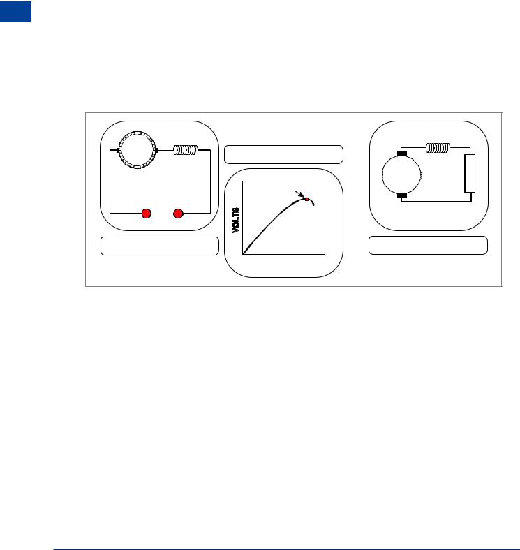
Characteristics of the Series Wound DC Generator
In a series wound DC generator, the armature (the rotating coil), the field coils (wire wrapped around the pole pieces to add strength to the magnetic field) and the external circuit are all in series.
This means that the same current which flows through the armature and external circuit also flows through the field coils.
Since the field current, which is also the load current, is large, the required strength of magnetic flux is obtained with a relatively small number of turns in the field windings. As the load draws more current from the generator this additional current increases the field strength and generates more voltage in the armature winding. A point is soon reached, A, where further increase in load current does not result in greater voltage, because the magnetic field has reached saturation point (this is the point where no more magnetic lines of force can be absorbed by the pole pieces). Because a constant voltage is required for aircraft systems the series generator cannot be used.
ARMATURE |
THE CHARACTERISTIC LOAD |
|
SERIES |
CURVE |
L |
FIELD |
|
O |
|
FIELD SATURATION |
A |
|
D |
|
|
POINT |
|
LOAD |
A |
|
|
|
|
A SERIES WOUND DC |
|
DIAGRAMMATIC VIEW |
GENERATOR |
|
|
|
|
|
|
LOAD CURRENT |
|
Figure 6.10 Series wound generator
Commutator Ripple
Commutator ripple is the term given to the fluctuation of the voltage output of a DC generator as the voltage rises and falls during the rotation of the armature loop, particularly at low RPM. By increasing the number of coils in the armature or the number of field coils, or indeed both then the pulsating or ripple effect of the DC produced by a generator can be reduced. The following diagram compares a single coil armature with a multiple coil.
88