


DC Electrics - DC Motors 7
Back EMF
The movement of the conductor in the magnetic field induces in it an electromotive force (EMF) which we know from Lenz’s law will oppose the rate of change of magnetic flux producing it. So an EMF is induced into the rotating part of the motor which tends to oppose the rotation of the motor. That is to say, the induced voltage will oppose the supply voltage. It is therefore called the back EMF.
The back EMF is proportional to motor speed and can never be as great as the supply input voltage. The difference between the applied EMF and the back EMF is always such that current can flow in the conductor and produce motion.
7
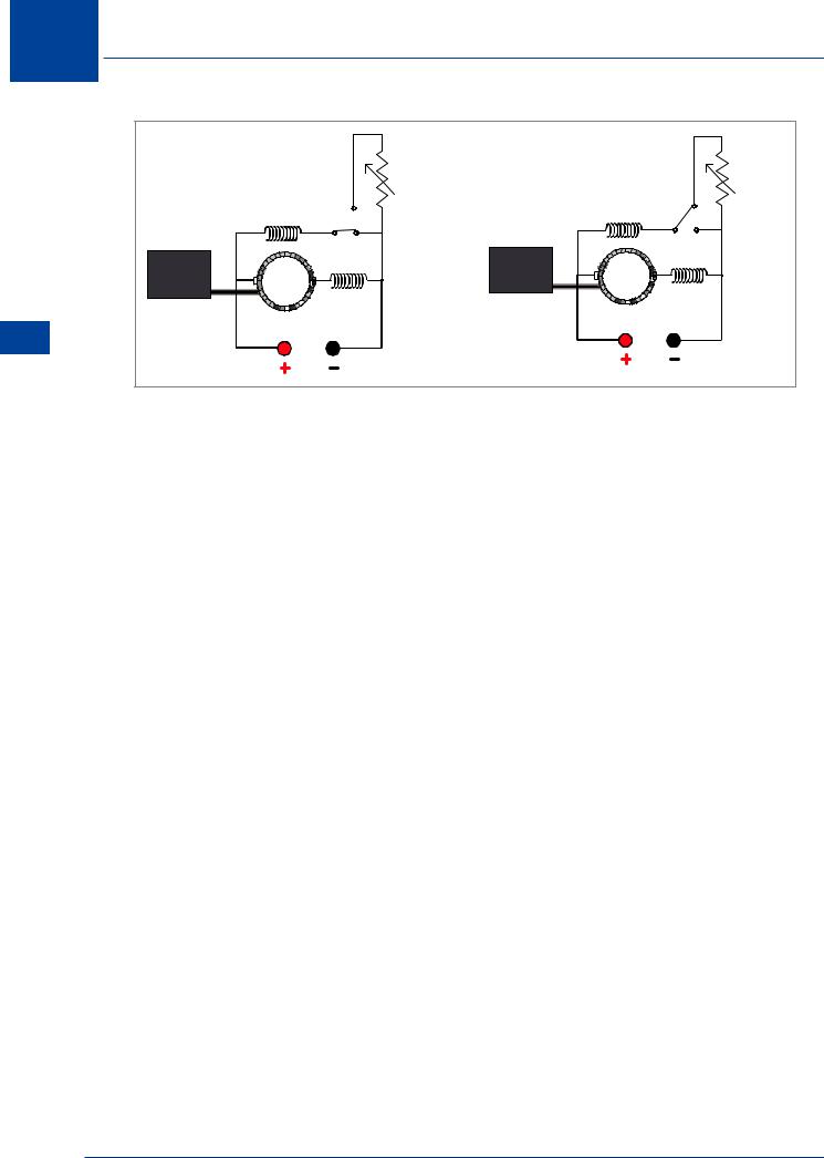
Slow Start Resistor
Some motors may have a slow start resistor in the circuit which is switched in series with the armature when the motor is first started to reduce the initial starting current before a back EMF has been established. The resistor is then bypassed by a centrifugal or time switch when the motor is turning to apply full current to the armature.
DC Electrics - DC Motors
Figure 7.4 Slow start resistor circuit
Commutation
The simplest form of motor has a single loop of wire able to rotate freely between the poles of a permanent magnet. A connection is made from the DC supply source (a battery) to the loop by brushes on a commutator; the 2 segments of which are connected to opposite ends of the loop. An example of this type of motor is shown (Figure 7.2a).
A single loop DC motor would not be able to turn heavy loads. To obtain a large mechanical output, with smooth running, the same improvements are made as in the case of the DC generator. That is a laminated iron core carrying a number of armature coils is used, and a corresponding number of commutator segments. The magnetic field is produced by an electro-
107

7 DC Electrics - DC Motors
magnet and its field coils and the spacing between the armature and pole pieces is kept as small as possible.
Series Wound Motors
The series wound motor has its field connected in series with the armature. The field coil consists of a few turns of heavy wire, and since the entire armature current flows through it, the field strength varies with the armature current. If the load on the motor increases, it slows down and the back EMF decreases, which allows the armature and field current to increase and so provide the heavier torque needed.
Motors DC - Electrics DC 7
Figure 7.5 Series wound motor
Series motors run slowly with heavy loads and very rapidly with light loads. If the load is completely removed, the motor can dangerously over speed and possibly disintegrate.
The reason for this is that the current required to rotate the motor with only a light load is very small, and consequently the series wound field coils produce only a weak magnetic field. This means that the motor cannot turn fast enough to generate the amount of back EMF needed to restore the balance. Series wound motors are variable speed motors and their speed changes with the applied load, for this reason they are not used either when a constant speed condition is needed, or where the load is intermittent. The series wound motor has a high starting torque and because of this it must never be started off load. Use of the series wound motor is mainly confined to electric actuators, starter motors and landing gear actuation.
Shunt Wound Motors
In a shunt wound motor, the field is connected directly across the voltage source, and is therefore independent of variation in load and armature current. The field coil consists of many turns of fine wire. The torque developed varies directly with the armature current.
If the load on the motor increases, the motor slows down, reducing the back EMF (which depends upon speed as well as on the constant field strength).
The reduced back EMF allows the armature current to increase, thereby furnishing the heavier torque needed to drive the increased load.
108

DC Electrics - DC Motors 7
If the load is decreased, the motor speeds up, increasing the back EMF and thereby decreasing the armature current and the torque developed whereupon the motor slows down. In a shunt wound motor, the variation of speed from ‘no-load’ to normal or ‘full’ load is only 10 % of the ‘no-load’ speed. Shunt wound motors are therefore considered constant speed motors.
Shunt wound motors are normally used where constant speeds under varying loads are required and tasks where it is possible for the motor to start under light or no-load conditions, such as fans, centrifugal pumps and motor generator units.
SHUNT FIELD |
|
|
7 |
ARMATURE |
- DC Motors |
|
DC Electrics |
A SHUNT WOUND DC |
DIAGRAMMATIC VIEW |
MOTOR |
|
Figure 7.6 Shunt wound motor |
|
Starter-generator Systems
Several types of turbine-powered aircraft are equipped with starter systems which use a starter generator having the dual function of engine starting and of supplying DC power to the aircraft’s electrical system.
Starter-generator units are basically compound-wound machines with two sets of field windings, one armature winding and a commutator. They are permanently coupled with the appropriate engine via a drive shaft and gear train.
For starting purposes, the unit functions as a fully compounded motor, the shunt field winding being supplied with current via a field changeover relay.
When the engine is running and the starter motor circuit is isolated from the power supply, the changeover relay is also automatically de-energized and its contacts connect the shunt field winding to a voltage regulator. The changeover relay contacts also permit DC to flow through the shunt winding to provide initial excitation of the field.
The machine thereafter functions as a conventional DC generator, its output being connected to the bus bar when it reaches the regulated level.
109
7 DC Electrics - DC Motors
Motors DC - Electrics DC 7
Motor mode |
|
Generator mode |
|
|
|
Voltage |
|
|
Voltage |
|
regulator |
|
|
regulator |
|
Shunt field |
|
Shunt field |
|
Engine |
Motor |
Engine |
Generator |
|
|
|
|||
|
|
|
|
|
Drive shaft |
Series field |
|
Drive shaft |
Series field |
|
|
|
||
Figure 7.7 Compound wound motor generator
The advantage of the starter-generator is that only one device provides both functions, thereby saving weight and complexity. The disadvantage is its inability to maintain full output at low RPM hence their use is typical on turbine engines which maintain a high engine RPM. A typical starter generator supplies 300 amps at 28 volts.
Actuators
Equipment and components which are installed in the modern aircraft are generally inaccessible for manual operation by the pilot or crew. Remote control of such items is achieved by the use of electrical actuators.
These actuators may be divided into two main groups:
•Solenoid actuators
•Motor actuators
Solenoid Actuators
Solenoid actuators are used to control hydraulic and pneumatic system selectors. Application of electrical power to a solenoid results in a valve opening under magnetic attraction.
Motor Actuator Construction
The actuator motor is a high speed reversible motor and it is widely used for the electrical operation of fuel valves, cooler shutters, trimming tabs, etc.
A wide ratio gear train is used to transmit the power and the actuator can be either rotary or linear in movement.
110