


AC Electrics - Logic Gates 17
The ‘EXCLUSIVE OR’ Gate
The ’EXCLUSIVE OR’ gate is designed to produce a ‘1’ output whenever its input signals are dissimilar.
An illustration of the representations of the ‘EXCLUSIVE OR’ gate is shown in Figure 17.6. This gate compares a maximum of two input signals to determine its output.
As shown in the truth table within Figure 17.6, if the input signals have like values, the output will be ‘0’, if the input signals have unlike values, the output will be ‘1’
A |
C |
B |
|
|
17 |
|
AC Electrics - Logic Gates |
Figure 17.6 Representations of the ‘EXCLUSIVE OR’ gate |
|
269

17 Questions
Questions
1. The logic function of the circuit shown is:
a. ‘AND’ b. ‘OR’ c. ‘NOR’ d. ‘NOT’
2.The circuit shown here represents:
a. an ‘AND’ gate b. a ‘NOR’ gate c. an ‘OR’ gate
d. an ‘EXCLUSIVE OR’ gate
3.The diagram is the equivalent of which of the accompanying symbols:
Questions 17
4.The gate symbols shown are:
a.‘AND’ and ‘NAND’ 


b.‘EXCLUSIVE OR’ and ‘EXCLUSIVE NOR’
c.‘OR’ and ‘NOR’
d.‘OR’ and ‘EXCLUSIVE OR’
5.A gate which requires that all inputs must be HIGH to obtain an output would be:
a.a ‘NOR’ gate
b.an ‘OR’ gate
c.an ‘AND’ gate
d.a ‘NOT’ gate
270

Questions 17
6.This diagram represents:
a.an inverter
b.an ‘AND’ gate
c.an ‘EXCLUSIVE NOR’ gate
d.an ‘OR’ gate
28 V |
7.To obtain logic ‘0’ at output ‘Z’ there must be:
|
a. |
logic ‘1’ at ‘X’ and logic ‘0’ at ‘Y’ |
|
|
|
|
|
|
|
|
|
|
|||||
|
b. |
logic ‘0’ at ‘X’ and logic ‘1’ at ‘Y’ |
|
|
|
|||
|
|
|
|
|||||
|
c. |
logic ‘1’ at ‘X’ and logic ‘1’ at ‘Y’ |
|
|
||||
|
d. |
logic ‘0’ at ‘X’ and logic ‘0’ at ‘Y’ |
|
|
|
|
|
|
|
|
|
|
|||||
|
|
|
|
|
||||
8. |
A transistor: |
|
|
|||||
|
a. |
can only be used as an amplifier |
|
|
||||
|
b. |
can be used as a demi-conductor to act as an automatic switch or an amplifier |
|
|
||||
|
c. |
is an inverted silicon controlled rectifier |
|
|
||||
|
d. |
can be used as a semiconductor to act as an automatic switch or an amplifier |
|
|
||||
9. |
A transistor: |
|
|
|||||
|
a. |
is made up of crystals in the arrangement of emitter, base and collector |
17 |
|||||
|
|
|
||||||
|
b. |
is made up of crystals in the arrangement of emitter, collector and base |
|
Questions |
||||
|
c. |
is made up of crystals in the arrangement of collector, emitter and base |
|
|||||
|
|
|
||||||
|
d. |
requires a current of ten amps through the base to transmit |
|
|
||||
10. |
A gate with only one input and one output: |
|
|
|||||
|
a. |
cannot be a ‘double’ gate |
|
|
||||
|
b. |
is a ‘NOT’ gate |
|
|
||||
|
c. |
can only be a ‘semi-gate’ |
|
|
||||
|
d. |
cannot be a ‘NOT’ gate |
|
|
||||
11. |
The two most commonly used gates are: |
|
|
|||||
|
a. |
‘NOT’ and ‘NOR’ |
|
|
||||
|
b. |
‘OR’ and ‘EXCLUSIVE AND’ |
|
|
||||
|
c. |
‘AND’ and ‘OR’ |
|
|
||||
|
d. |
‘AND’ and ‘NAND’ |
|
|
||||
12. |
Truth tables illustrate the relationship between: |
|
|
|||||
|
a. |
inputs and outputs |
|
|
||||
|
b. |
integrated gates for trouble shooting |
|
|
||||
|
c. |
the sequence of operation of the gates |
|
|
||||
|
d. |
electronic and electrical circuits |
|
|
||||
271
17 Questions
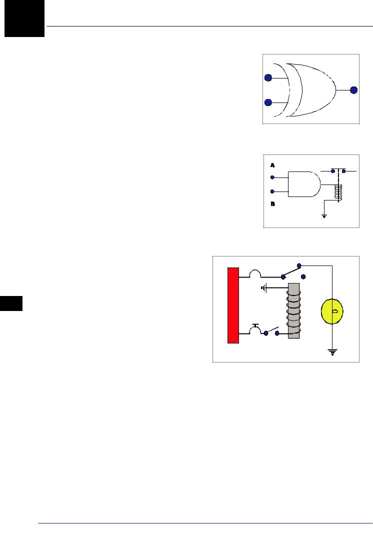
13.The output expression for this type of gate is:
a.‘AND’
b. ‘EXCLUSIVE NOR’ c. ‘EXCLUSIVE OR’
d.‘EXCLUSIVE NOT’
14.In order to energize the relay shown in this circuit, the logic state at the inputs must be:
a.logic ‘0’ at points ‘A’ and ‘B’
b. logic ‘0’ at point ‘A’ and logic ‘1’ at point ‘B’ c. logic ‘1’ at points ‘A’ and ‘B’
d. always identical at points ‘A’ and ‘B’
15.The type of logic gate represented by this diagram is:
a.‘OR’
b. |
‘NAND’ |
|
|
|
|
||
c. |
‘AND’ |
|
|
d.‘NOT’
Questions 17
272

Questions 17
Questions 17
273