- •Textbook Series
- •Contents
- •1 DC Electrics - Basic Principles
- •Introduction
- •Electromotive Force (EMF)
- •Current
- •Resistance
- •Factors Affecting the Resistance
- •Units of Resistance
- •Resistors
- •Power
- •Series and Parallel Circuits
- •Kirchoff’s Laws
- •Annex A
- •2 DC Electrics - Switches
- •Switches
- •Proximity Detectors
- •Time Switches
- •Centrifugal Switches
- •3 DC Electrics - Circuit Protection and Capacitors
- •Electrical Faults
- •Circuit Protection Devices
- •Fuses
- •The Cartridge Fuse
- •Spare Fuses
- •High Rupture Capacity (HRC) Fuses
- •Dummy Fuses
- •Current Limiters
- •Circuit Breakers
- •Reverse Current Circuit Breakers
- •Capacitors
- •Capacitance
- •Capacitor in a DC Circuit
- •Capacitor in an AC Circuit
- •Capacitors in Parallel
- •Capacitors in Series
- •4 DC Electrics - Batteries
- •Batteries
- •Secondary Cells
- •Lead Acid Battery
- •Alkaline Battery (Nickel Cadmium, NiCad)
- •Battery Checks
- •Battery Charging
- •Secondary Batteries Summary
- •5 DC Electrics - Magnetism
- •Magnetism
- •Temporary Magnets
- •Permanent Magnets
- •Permeability
- •Magnetism
- •The Molecular Structure of Magnets
- •The Magnetic Effect of a Current
- •The Corkscrew Rule
- •The Magnetic Field of a Solenoid
- •The Right Hand Grasp Rule
- •The Strength of the Field of a Solenoid
- •Solenoid and Relay
- •The Forces on a Conductor Which is Carrying a Current
- •Questions
- •Answers
- •6 DC Electrics - Generators and Alternators
- •Electromagnetic Induction
- •Fleming’s Right Hand Rule
- •Faraday’s Law
- •Lenz’s Law
- •Simple Generator
- •Simple DC Generator
- •Characteristics of the Series Wound DC Generator
- •Commutator Ripple
- •Characteristics of the Shunt Wound DC Generator
- •A Compound Wound DC Generator
- •Flashing the Generator Field
- •Alternators
- •Voltage Control
- •Voltage Regulator Operation
- •Layout of a Generator System
- •Load Sharing Circuits
- •Operation of Load Sharing Circuit
- •7 DC Electrics - DC Motors
- •Electric Motors
- •Fleming’s Left Hand Rule
- •Practical DC Motor
- •Back EMF
- •Slow Start Resistor
- •Commutation
- •Series Wound Motors
- •Shunt Wound Motors
- •Starter-generator Systems
- •Actuators
- •Solenoid Actuators
- •Motor Actuator Construction
- •The Split Field Series Actuator
- •The Split Field Series Actuator Operation
- •Motor Actuators
- •Rotary Actuators
- •Linear Actuators
- •Actuator Brakes
- •Actuator Clutches
- •Visual Indicators Used with Linear Actuators
- •Visual Indicators Used with Rotary Actuators
- •Indicator Lights
- •Electromagnetic Indicators
- •Questions
- •Answers
- •8 DC Electrics - Aircraft Electrical Power Systems
- •Aircraft Electrical Power Systems
- •Dipole or Two Wire System
- •Single Pole (Unipole or Earth Return) System
- •Generators and Alternators
- •Voltage Regulators
- •Overvoltage Protection Unit
- •Generator Cut-out or Reverse Current Relay
- •Rectifiers
- •Inverters
- •The Generator Differential Cut-out
- •Generator (or Alternator) Warning Light
- •Generator (or Alternator) Master Switch
- •Monitoring Instruments
- •Ammeters and Voltmeters
- •The Battery
- •Bus Bars
- •Bus Bar Systems
- •Parallel Bus Bar System
- •Load Shedding
- •Generator or Alternator Failure
- •9 DC Electrics - Bonding and Screening
- •Bonding
- •The Static Discharge System or Static Wicks
- •Discharge of Static on Touchdown
- •Screening
- •Questions
- •Answers
- •10 DC Electrics - Specimen Questions
- •Questions – General 1
- •Questions – General 2
- •Answers – General 1
- •Answers – General 2
- •11 AC Electrics - Introduction to AC
- •Introduction
- •The Nature of Alternating Current
- •Terms
- •The Relationship of Current and Voltage in an AC Circuit
- •Resistance in AC Circuits
- •Inductance in AC Circuits
- •Inductive Reactance
- •Capacitance in AC Circuits
- •Capacitive Reactance
- •Impedance
- •Resonant Circuits
- •Summary
- •Power in AC Circuits
- •Power in a Purely Resistive Circuit
- •Power in a Purely Inductive Circuit
- •Power in a Capacitive Circuit
- •Power in a Practical AC Circuit
- •Power Factor
- •Power Factor Resume
- •Questions
- •Answers
- •12 AC Electrics - Alternators
- •Introduction to Aircraft Power Supplies
- •Generators / Alternators
- •Rotating Armature Alternator
- •Rotating Field Alternator
- •Alternator Output Rating
- •A Single Phase Alternator
- •Polyphase Circuits
- •Three Phase Alternator Connections
- •The Four Wire Star Connection
- •Delta Connected Alternator
- •Practical AC Generators
- •Brushed Alternators
- •Brushless Alternators
- •Frequency Wild Alternators
- •Obtaining a Constant Frequency Supply from a Frequency Wild System
- •Constant Frequency Alternators
- •Constant Speed Generator Drive Systems
- •CSDU Fault Indications in the Cockpit
- •The Drive Disconnect Unit (Dog Clutch Disconnect)
- •Variable Speed Constant Frequency Power Systems (VSCF)
- •Self-excited Generators
- •Load Sharing or Paralleling of Constant Frequency Alternators
- •Real Load
- •Reactive Load
- •Parallel Connection
- •Before Connecting in Parallel
- •Layout of a Paralleled System
- •Real Load Sharing
- •Reactive Load Sharing
- •Load Sharing General
- •Alternator Cooling
- •Generator Fault Protection
- •Bus Tie Breakers (BTBs)
- •Discriminatory Circuits
- •Differential Fault Protection
- •Synchronizing Units
- •Generator Failure Warning Light
- •Load Meters
- •Voltage and Frequency Meters
- •Generator Control Unit (GCU)
- •Emergency Supplies
- •The Ram Air Turbine (RAT)
- •The Auxiliary Power Unit (APU)
- •The Static Inverter
- •Ground Power Constant Frequency Supply System
- •Typical Controls and Indications
- •Questions
- •Answers
- •13 AC Electrics - Practical Aircraft Systems
- •Power Distribution
- •The Split Bus System
- •Parallel Bus Bar System
- •Questions
- •Answers
- •14 AC Electrics - Transformers
- •Transformers
- •Transformation Ratio
- •Power in a Transformer
- •Three Phase Transformers
- •Autotransformers
- •Rectification of Alternating Current
- •Half Wave Rectification
- •Full Wave Rectification
- •Three Phase Rectifiers
- •Transformer Rectifier Units (TRUs)
- •Inverters
- •Questions
- •Answers
- •15 AC Electrics - AC Motors
- •Alternating Current Motors
- •The Principle of Operation of AC Motors
- •The Synchronous Motor
- •The Induction Motor
- •The Squirrel Cage Rotor
- •The Induction Motor Stator
- •Slip Speed
- •Starting Single Phase Induction Motors
- •Fault Operation
- •Questions
- •Answers
- •16 AC Electrics - Semiconductors
- •An Introduction to Semiconductors
- •Conductors and Insulators
- •Semiconductors
- •N-Type Material
- •P-Type Material
- •Current Flow
- •The P-N Junction
- •Reverse Bias
- •Forward Bias
- •The Junction Diode
- •The Bipolar or Junction Transistor
- •Summary
- •17 AC Electrics - Logic Gates
- •An Introduction to Logic Gates
- •Binary Logic
- •Truth Tables
- •Gate Symbols
- •Positive and Negative Logic
- •The ‘AND’ Gate
- •The ‘OR’ Gate
- •The ‘INVERT’ or ‘NOT’ Gate
- •The ‘NAND’ Gate
- •The ‘NOR’ Gate
- •The ‘EXCLUSIVE OR’ Gate
- •Questions
- •Answers
- •18 Index
AC Electrics - AC Motors 15
The Induction Motor
The induction motor gets its name from the fact that an alternating current is induced in the rotor by the rotating magnetic field in the stator.
It is the most commonly used because of its simplicity, its robustness and because it is relatively cheap to produce.
This relative cheapness is mainly because of the fact that the rotor is a self-contained unit and not connected to the supply.
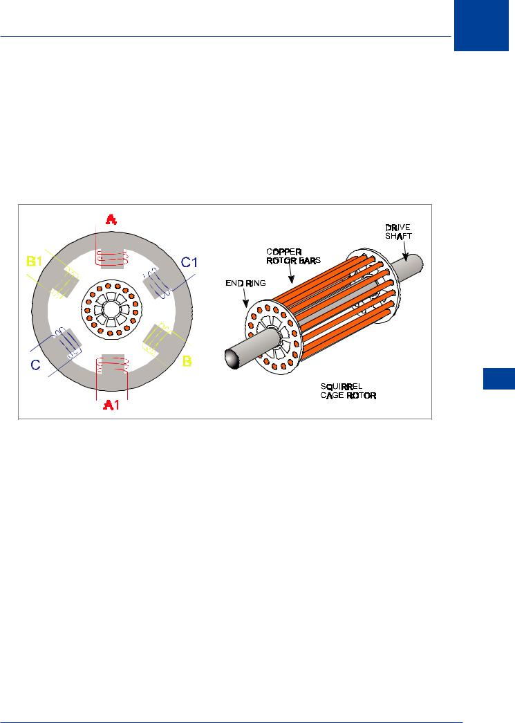
Figure 15.2 Squirrel cage induction motor
The Squirrel Cage Rotor
The rotor consists of a cylindrical laminated iron core which has a number of longitudinal bars of copper evenly spaced around the circumference. These bars are joined at either end by rings of the same material to form a composite structure called a Squirrel Cage. The rotor bars are of very low resistance material so that a large current can flow through them.
The Induction Motor Stator
The stator consists of windings, the number of which is related to the number of poles and also to the number of phases of the power supply. The rotating magnetic field produced in the stator cuts through the bars of the rotor which is basically a closed circuit of low resistance.
The resultant induced voltage creates a relatively large current flow in the squirrel cage. This current flow sets up its own magnetic field which interacts with the rotating field of the stator to produce a torque. If a three phase motor has two phases of its supply reversed, then its direction of rotation will be reversed also.
AC Electrics - AC Motors 15
243
15 AC Electrics -AC Motors
Slip Speed
Motors AC - Electrics AC 15
The speed of the motor is determined by the frequency of the supply and the load on the motor. The rotor never quite reaches true synchronous speed, if it did then the squirrel cage bars would not be cut by any lines of force and thus would not produce the induced voltage. The difference between synchronous speed and rotor speed is called the slip speed or rotor slip. A typical value of slip would be 5%. Because of the difference in speed between the stator field and rotor, the induction motor is sometimes referred to as being asynchronous.
Starting Single Phase Induction Motors
Single phase induction motors are not self-starting. Different methods are used to assist in making them self-starting. The most common method is the use of what is called a Split Phase Winding.
If the current in the split phase winding can be made to lead or lag the current in the main winding by 90° then a rotating field can be produced.
The lead or lag can be produced by the following methods:
•Resistance starting
•Inductance starting
•Resistance / inductance starting
•Capacitance starting
The application of each method depends on the power output of the motor, e.g. capacitance started motors are usually of less than 2 HP output.
Fault Operation
Occasionally the failure of one phase of the supply to a three phase induction motor does happen. If the motor is lightly loaded then it will probably continue to run at about half of its normal speed. This will create a humming noise in the motor which, because of the usually remote locations in which the motors are mounted, will probably not make itself apparent. The fault usually becomes apparent the next time an attempt is made to run the motor, when it will not start.
244
Questions
Questions
1.Synchronous motors are usually supplied by:
a.three phase AC
b.single phase AC
c.DC to the stator
d.DC to the stator and AC to the rotor
2.Reversing two phases to a three phase motor will:
a.blow the phase fuses
b.cause the motor to run in reverse
c.overheat the stator windings
d.stall the motor
3.A synchronous motor runs at a speed that depends upon the supply:
a.voltage
b.current
c.reactance
d.frequency
4.If one phase of the supply to a three phase motor fails, then:
a.the motor will continue to run at the same speed
b.will slow down and stop
c.will stop immediately
d.will run at about half speed but will not start on its next selection
5.The basic principle of operation of a 3 phase induction motor is:
a.a rotating field created in the rotor
b.a rotating field created in the stator
c.a stationary field created in the stator
d.a stationary field created in the rotor
6.In an induction motor:
a.the rotor is star connected
b.magnetic fields blend evenly with one another
c.AC is induced in the rotor
d.a DC supply produces DC in the rotor
7.In a synchronous motor, the rotor is:
a.energized by DC and it lines up with the magnetic field in the stator
b.wave wound
c.both AC and DC energized
d.impeded by the AC induced into it
15
Questions 15
245
15 Questions
8.An induction motor has:
a.slip rings and brushes
b.a commutator
c.no slip ring or brushes
d.slip rings but no brushes
9.A squirrel cage rotor:
a.is not connected to the supply
b.is expensive to produce
c.rotates at exactly synchronous speed
d.is a closed circuit of high resistance
10.A starting circuit for a powerful single phase induction motor might be:
a.a capacitance starter
b.a resistance / inductance starter
c.a cartridge starter
d.a bump starter
Questions 15
246
Questions 15
Questions 15
247