

AC Electrics - Logic Gates 17
The ‘OR’ Gate
The ‘OR’ gate is used to represent a situation where any input being ‘1’ (on) will produce a ‘1’ (on) output. To be an ‘OR’ gate, input No. 1 or input No. 2 or input No. 3, etc, must be ‘1’ to produce a ‘1’ output.
Only if all inputs become ‘0’ will the ‘OR’ gate produce a ‘0’ output. If any input is a ‘1’, regardless of the other input values, the ‘OR’ gate will produce a ‘1’ output.
A two-input ‘OR’ gate symbol and corresponding truth table are illustrated in Figure 17.2.
A simple ‘OR’ circuit may be made up of two switches in parallel controlling one light. If either switch is ‘1’ (on), the light will turn ‘1’ (on).
The OR gate may be called an “ANY or ALL“ gate.
A |
|
A |
|
C |
|
|
C |
|
|
|
|
B |
|
B |
|
|
|
|
|
17 |
|
|
AC Electrics - Logic Gates |
|
Figure 17.2 Representation of the ‘OR’ gate |
|
265
17 AC Electrics -Logic Gates
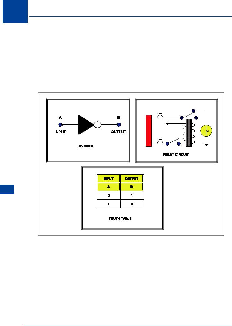
The ‘INVERT’ or ‘NOT’ Gate
The ‘INVERT’ gate is used to reverse the condition of the input signal. The ‘INVERT’ gate contains only one input and one output, and is most often used in conjunction with other gates.
The ‘INVERT’ gate is sometimes referred to as a ‘NOT’ gate. The symbol and truth table for an ‘INVERT’ gate are shown in Figure 17.3.
An ‘INVERT’ circuit might comprise a switch controlling a normally closed relay which turns on or off a light. As also illustrated in Figure 17.3, if the switch is turned ‘1’ (on), the light is ‘0’ (off).
B
A
Gates Logic - Electrics AC 17
Figure 17.3 Representation of the ‘INVERT’ or ‘NOT’ gate
266
AC Electrics - Logic Gates 17
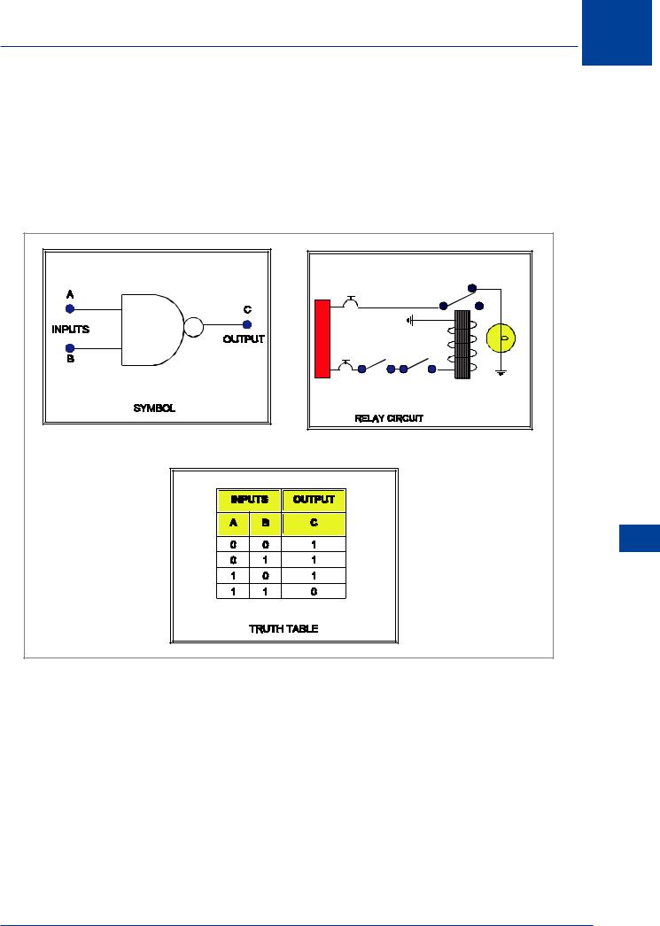
The ‘NAND’ Gate
The ‘NAND’ gate is an ‘AND’ gate with an inverted output. The output of this gate will be ‘1’ if any input is ‘0’. This is the exact opposite of an ‘AND’ gate. The representations of a ‘NAND’ gate are shown in Figure 17.4.
The ‘NAND’ gate circuit illustrated in Figure 17.4 shows if either switch is closed, there will be no output.
|
C |
A |
B |
|
17 |
|
AC Electrics - Logic Gates |
Figure 17.4 The representation of the ‘NAND’ gate |
|
267

17
Gates Logic - Electrics AC 17
AC Electrics -Logic Gates
The ‘NOR’ Gate
The ‘NOR’ gate is an ‘OR’ gate with an inverted output. This results in a gate where any input being ‘1’ will create a ‘0’ output. The ‘NOR’ symbol, the truth table and the relay circuit which represent a ‘NOR’ gate are all illustrated in Figure 17.5.
C |
A |
B |
Figure 17.5 Representations of the ‘NOR’ gate
268