

Chapter
12
AC Electrics - Alternators
Introduction to Aircraft Power Supplies |
|
|
187 |
Generators / Alternators . . . . . . . . . . . . . . . . . . . . |
. . . . |
. |
187 |
Rotating Armature Alternator . . . . . . . . . . . . . . . . . . |
. . . . |
. |
187 |
Rotating Field Alternator |
|
|
188 |
Alternator Output Rating . . . . . . . . . . . . . . . . . . . . |
. . . . |
|
.188 |
A Single Phase Alternator . . . . . . . . . . . . . . . . . . . . |
. . . . |
|
.188 |
Polyphase Circuits |
|
|
189 |
Three Phase Alternator Connections . . . . . . . . . . . . . . . . |
. . . . |
|
.190 |
The Four Wire Star Connection . . . . . . . . . . . . . . . . . . |
. . . . |
|
.191 |
Delta Connected Alternator . . . . . . . . . . . . . . . . . . . |
. . . . |
. |
192 |
Practical AC Generators |
|
|
192 |
Brushed Alternators |
|
|
193 |
Brushless Alternators . . . . . . . . . . . . . . . . . . . . . . |
. . . . |
|
.194 |
Frequency Wild Alternators . . . . . . . . . . . . . . . . . . . |
. . . . |
. |
194 |
Obtaining a Constant Frequency Supply from a Frequency Wild System . . . |
. . . . |
. 195 |
|
Constant Frequency Alternators . . . . . . . . . . . . . . . . . . |
. . . . |
|
.195 |
Constant Speed Generator Drive Systems |
|
|
195 |
CSDU Fault Indications in the Cockpit . . . . . . . . . . . . . . . . |
. . . . |
|
.195 |
The Drive Disconnect Unit (Dog Clutch Disconnect) . . . . . . . . . . |
. . . . |
. |
196 |
Variable Speed Constant Frequency Power Systems (VSCF) . . . . . . . . |
. . . . |
|
.196 |
Self-excited Generators |
|
|
197 |
Load Sharing or Paralleling of Constant Frequency Alternators . . . . . . |
. . . . |
. |
197 |
Real Load . . . . . . . . . . . . . . . . . . . . . . . . . . |
. . . . |
|
.197 |
Reactive Load . . . . . . . . . . . . . . . . . . . . . . . . |
. . . . |
. |
197 |
Parallel Connection . . . . . . . . . . . . . . . . . . . . . . |
. . . . |
. |
198 |
Before Connecting in Parallel . . . . . . . . . . . . . . . . . . |
. . . . |
. |
198 |
Layout of a Paralleled System . . . . . . . . . . . . . . . . . . |
. . . . |
. |
199 |
Real Load Sharing |
|
|
199 |
Continued Overleaf
185

12 AC Electrics -Alternators
Alternators - Electrics AC 12
Reactive Load Sharing . . . . . . . . . . . . . . . . . |
. . |
. . |
. . |
. |
. |
200 |
Load Sharing General |
|
|
|
|
|
201 |
Alternator Cooling . . . . . . . . . . . . . . . . . . |
. . |
. . |
. . |
. . |
|
.201 |
Generator Fault Protection |
|
|
|
|
|
202 |
Bus Tie Breakers (BTBs) |
|
|
|
|
|
202 |
Discriminatory Circuits . . . . . . . . . . . . . . . . . |
. . |
. . |
. . |
. |
. |
202 |
Differential Fault Protection . . . . . . . . . . . . . . . |
. . |
. . |
. . |
. |
. |
202 |
Synchronizing Units |
|
|
|
|
|
203 |
Generator Failure Warning Light |
|
|
|
|
|
203 |
Load Meters |
|
|
|
|
|
203 |
Voltage and Frequency Meters . . . . . . . . . . . . . . |
. . |
. . |
. . |
. |
. |
203 |
Generator Control Unit (GCU) . . . . . . . . . . . . . . |
. . |
. . |
. . |
. . |
|
.204 |
Emergency Supplies |
|
|
|
|
|
204 |
The Ram Air Turbine (RAT) |
|
|
|
|
|
204 |
The Auxiliary Power Unit (APU) . . . . . . . . . . . . . . |
. . |
. . |
. . |
. |
. |
204 |
The Static Inverter |
|
|
|
|
|
205 |
Ground Power Constant Frequency Supply System |
|
|
|
|
|
205 |
Typical Controls and Indications . . . . . . . . . . . . . . |
. . |
. . |
. . |
. |
. |
206 |
Questions . . . . . . . . . . . . . . . . . . . . . . |
. . |
. . |
. . |
. |
. |
208 |
Answers . . . . . . . . . . . . . . . . . . . . . . |
. . |
. . |
. . |
. . |
|
.218 |
186

AC Electrics - Alternators
Introduction to Aircraft Power Supplies
The requirement for more power to operate larger pieces of electrical equipment as passenger aircraft grew in size now means that most large commercial aircraft use alternating current distribution systems.
The industry standard that has evolved for constant frequency aircraft is: 115 V/ 200 V/ 400 Hz
/ 3 phase
And the requirement for DC is satisfied by converting AC to 28 V DC using transformer rectifier units (TRUs), while retaining the battery for emergency use.
The distribution system is laid out in a similar fashion to the DC aircraft using a system of bus bars having a distinct hierarchy, the emphasis being placed on the ability of the system to cope with failure with the minimum loss of electrical services.
As in a DC system, the AC generators can be operated in parallel if the designer requires.
This chapter will explain different types of AC generator, their operation, control and protection and some typical aircraft AC systems.
Generators / Alternators
In a DC generator the rotating part is always the armature. In an AC generator this is not generally true.
Another name for an AC generator is Alternator.
There are two types of alternator
•Rotating Armature.
•Rotating Field.
Rotating Armature Alternator
The rotating armature alternator is similar in construction to a DC generator in that the armature rotates in a stationary magnetic field. As it does so, an EMF is induced into it, and this EMF, rather than being converted to DC as it is in the commutator of a DC machine, is taken out as AC through Slip Rings.
The rotating armature is only used in very small output alternators and is not generally used for supplying AC systems.
12
AC Electrics - Alternators 12
187
12 AC Electrics -Alternators
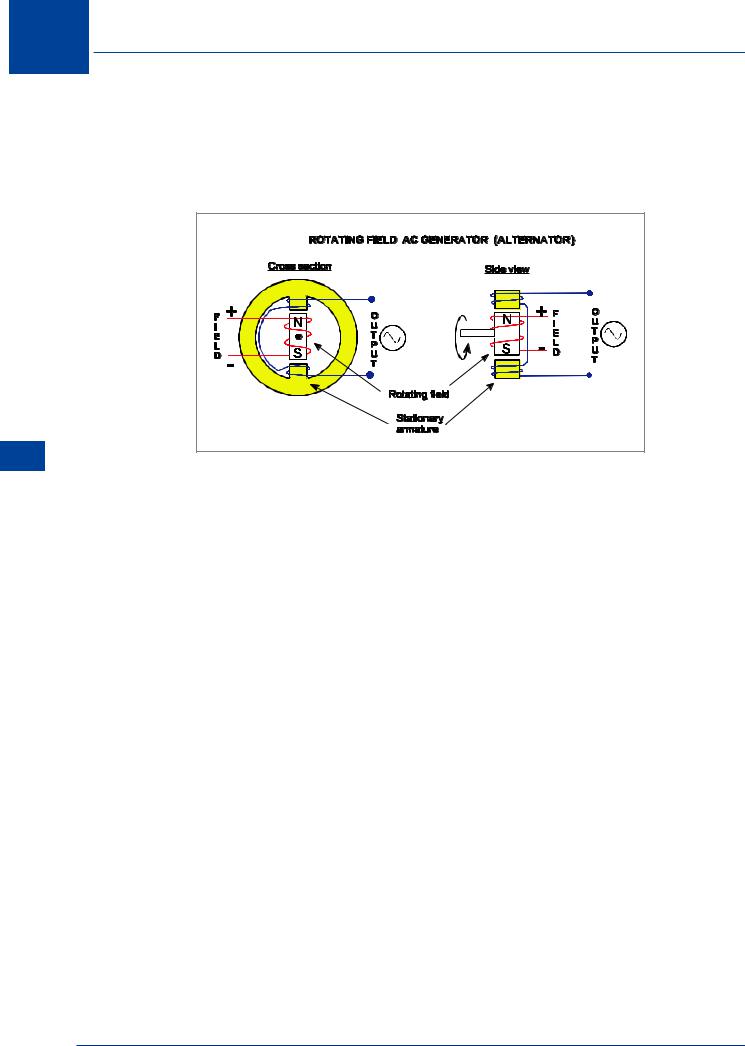
Rotating Field Alternator
Most practical alternators are designed with a rotating field and a stationary armature so that the rotor, the moving part, carries the field windings. The field can either be energized by a permanent magnet or by DC from a separate source.
Alternators - Electrics AC 12
Figure 12.1 Rotating field alternator
NOTE: The field MUST be energized by DC to keep the correct polarity in the rotor.
One advantage of a rotating field alternator is that only a low current is fed through slip rings to the field windings.
The output is taken from the stationary armature windings, which means that problems associated with arcing from the brush gear are greatly reduced. Figure 12.1 illustrates a simple rotating field alternator.
Alternator Output Rating
The maximum output current from an alternator depends on the amount of heat loss which can be sustained in the armature. This power loss heats up the conductors and can, in extreme cases, destroy the insulation of the windings. Alternators are rated in terms of this armature current as well as by their voltage output. Thus every alternator is rated in Volt Amperes (VA) or Kilovolt Amperes (kVA), the Apparent Power.
A Single Phase Alternator
A single phase alternator has its stator windings connected in series to supply the output. The stator windings (coils) are connected so as to be series-aiding, so that the induced voltages in them are in phase. The rotor consists of two poles of opposite polarity. This is illustrated in
Figure 12.2.
188