- •Textbook Series
- •Contents
- •1 DC Electrics - Basic Principles
- •Introduction
- •Electromotive Force (EMF)
- •Current
- •Resistance
- •Factors Affecting the Resistance
- •Units of Resistance
- •Resistors
- •Power
- •Series and Parallel Circuits
- •Kirchoff’s Laws
- •Annex A
- •2 DC Electrics - Switches
- •Switches
- •Proximity Detectors
- •Time Switches
- •Centrifugal Switches
- •3 DC Electrics - Circuit Protection and Capacitors
- •Electrical Faults
- •Circuit Protection Devices
- •Fuses
- •The Cartridge Fuse
- •Spare Fuses
- •High Rupture Capacity (HRC) Fuses
- •Dummy Fuses
- •Current Limiters
- •Circuit Breakers
- •Reverse Current Circuit Breakers
- •Capacitors
- •Capacitance
- •Capacitor in a DC Circuit
- •Capacitor in an AC Circuit
- •Capacitors in Parallel
- •Capacitors in Series
- •4 DC Electrics - Batteries
- •Batteries
- •Secondary Cells
- •Lead Acid Battery
- •Alkaline Battery (Nickel Cadmium, NiCad)
- •Battery Checks
- •Battery Charging
- •Secondary Batteries Summary
- •5 DC Electrics - Magnetism
- •Magnetism
- •Temporary Magnets
- •Permanent Magnets
- •Permeability
- •Magnetism
- •The Molecular Structure of Magnets
- •The Magnetic Effect of a Current
- •The Corkscrew Rule
- •The Magnetic Field of a Solenoid
- •The Right Hand Grasp Rule
- •The Strength of the Field of a Solenoid
- •Solenoid and Relay
- •The Forces on a Conductor Which is Carrying a Current
- •Questions
- •Answers
- •6 DC Electrics - Generators and Alternators
- •Electromagnetic Induction
- •Fleming’s Right Hand Rule
- •Faraday’s Law
- •Lenz’s Law
- •Simple Generator
- •Simple DC Generator
- •Characteristics of the Series Wound DC Generator
- •Commutator Ripple
- •Characteristics of the Shunt Wound DC Generator
- •A Compound Wound DC Generator
- •Flashing the Generator Field
- •Alternators
- •Voltage Control
- •Voltage Regulator Operation
- •Layout of a Generator System
- •Load Sharing Circuits
- •Operation of Load Sharing Circuit
- •7 DC Electrics - DC Motors
- •Electric Motors
- •Fleming’s Left Hand Rule
- •Practical DC Motor
- •Back EMF
- •Slow Start Resistor
- •Commutation
- •Series Wound Motors
- •Shunt Wound Motors
- •Starter-generator Systems
- •Actuators
- •Solenoid Actuators
- •Motor Actuator Construction
- •The Split Field Series Actuator
- •The Split Field Series Actuator Operation
- •Motor Actuators
- •Rotary Actuators
- •Linear Actuators
- •Actuator Brakes
- •Actuator Clutches
- •Visual Indicators Used with Linear Actuators
- •Visual Indicators Used with Rotary Actuators
- •Indicator Lights
- •Electromagnetic Indicators
- •Questions
- •Answers
- •8 DC Electrics - Aircraft Electrical Power Systems
- •Aircraft Electrical Power Systems
- •Dipole or Two Wire System
- •Single Pole (Unipole or Earth Return) System
- •Generators and Alternators
- •Voltage Regulators
- •Overvoltage Protection Unit
- •Generator Cut-out or Reverse Current Relay
- •Rectifiers
- •Inverters
- •The Generator Differential Cut-out
- •Generator (or Alternator) Warning Light
- •Generator (or Alternator) Master Switch
- •Monitoring Instruments
- •Ammeters and Voltmeters
- •The Battery
- •Bus Bars
- •Bus Bar Systems
- •Parallel Bus Bar System
- •Load Shedding
- •Generator or Alternator Failure
- •9 DC Electrics - Bonding and Screening
- •Bonding
- •The Static Discharge System or Static Wicks
- •Discharge of Static on Touchdown
- •Screening
- •Questions
- •Answers
- •10 DC Electrics - Specimen Questions
- •Questions – General 1
- •Questions – General 2
- •Answers – General 1
- •Answers – General 2
- •11 AC Electrics - Introduction to AC
- •Introduction
- •The Nature of Alternating Current
- •Terms
- •The Relationship of Current and Voltage in an AC Circuit
- •Resistance in AC Circuits
- •Inductance in AC Circuits
- •Inductive Reactance
- •Capacitance in AC Circuits
- •Capacitive Reactance
- •Impedance
- •Resonant Circuits
- •Summary
- •Power in AC Circuits
- •Power in a Purely Resistive Circuit
- •Power in a Purely Inductive Circuit
- •Power in a Capacitive Circuit
- •Power in a Practical AC Circuit
- •Power Factor
- •Power Factor Resume
- •Questions
- •Answers
- •12 AC Electrics - Alternators
- •Introduction to Aircraft Power Supplies
- •Generators / Alternators
- •Rotating Armature Alternator
- •Rotating Field Alternator
- •Alternator Output Rating
- •A Single Phase Alternator
- •Polyphase Circuits
- •Three Phase Alternator Connections
- •The Four Wire Star Connection
- •Delta Connected Alternator
- •Practical AC Generators
- •Brushed Alternators
- •Brushless Alternators
- •Frequency Wild Alternators
- •Obtaining a Constant Frequency Supply from a Frequency Wild System
- •Constant Frequency Alternators
- •Constant Speed Generator Drive Systems
- •CSDU Fault Indications in the Cockpit
- •The Drive Disconnect Unit (Dog Clutch Disconnect)
- •Variable Speed Constant Frequency Power Systems (VSCF)
- •Self-excited Generators
- •Load Sharing or Paralleling of Constant Frequency Alternators
- •Real Load
- •Reactive Load
- •Parallel Connection
- •Before Connecting in Parallel
- •Layout of a Paralleled System
- •Real Load Sharing
- •Reactive Load Sharing
- •Load Sharing General
- •Alternator Cooling
- •Generator Fault Protection
- •Bus Tie Breakers (BTBs)
- •Discriminatory Circuits
- •Differential Fault Protection
- •Synchronizing Units
- •Generator Failure Warning Light
- •Load Meters
- •Voltage and Frequency Meters
- •Generator Control Unit (GCU)
- •Emergency Supplies
- •The Ram Air Turbine (RAT)
- •The Auxiliary Power Unit (APU)
- •The Static Inverter
- •Ground Power Constant Frequency Supply System
- •Typical Controls and Indications
- •Questions
- •Answers
- •13 AC Electrics - Practical Aircraft Systems
- •Power Distribution
- •The Split Bus System
- •Parallel Bus Bar System
- •Questions
- •Answers
- •14 AC Electrics - Transformers
- •Transformers
- •Transformation Ratio
- •Power in a Transformer
- •Three Phase Transformers
- •Autotransformers
- •Rectification of Alternating Current
- •Half Wave Rectification
- •Full Wave Rectification
- •Three Phase Rectifiers
- •Transformer Rectifier Units (TRUs)
- •Inverters
- •Questions
- •Answers
- •15 AC Electrics - AC Motors
- •Alternating Current Motors
- •The Principle of Operation of AC Motors
- •The Synchronous Motor
- •The Induction Motor
- •The Squirrel Cage Rotor
- •The Induction Motor Stator
- •Slip Speed
- •Starting Single Phase Induction Motors
- •Fault Operation
- •Questions
- •Answers
- •16 AC Electrics - Semiconductors
- •An Introduction to Semiconductors
- •Conductors and Insulators
- •Semiconductors
- •N-Type Material
- •P-Type Material
- •Current Flow
- •The P-N Junction
- •Reverse Bias
- •Forward Bias
- •The Junction Diode
- •The Bipolar or Junction Transistor
- •Summary
- •17 AC Electrics - Logic Gates
- •An Introduction to Logic Gates
- •Binary Logic
- •Truth Tables
- •Gate Symbols
- •Positive and Negative Logic
- •The ‘AND’ Gate
- •The ‘OR’ Gate
- •The ‘INVERT’ or ‘NOT’ Gate
- •The ‘NAND’ Gate
- •The ‘NOR’ Gate
- •The ‘EXCLUSIVE OR’ Gate
- •Questions
- •Answers
- •18 Index
Chapter
2
DC Electrics - Switches
Switches . . . . . . . . . . . . . . |
. . . . . . . |
. . |
. . |
. . |
. . . . |
|
. 29 |
Proximity Detectors |
|
|
|
|
|
|
30 |
Time Switches . . . . . . . . . . . . |
. . . . . . |
. . |
. . |
. . |
. . . . |
. |
33 |
Centrifugal Switches . . . . . . . . . . |
. . . . . . |
. . |
. . |
. . |
. . . . |
. |
33 |
27
2 DC Electrics - Switches
Switches - Electrics DC 2
28
DC Electrics - Switches 2
Switches
The initiation and control of aircraft circuits is achieved by switches and relays. Some typical switches are described here.
Toggle Switch
A general purpose switch common in older aircraft having a number of isolating contacts inside. It can be a two position switch (on or off) or a multi-position switch sprung biased to the centre or off position and then pressed and held to select in the desired direction.
Figure 2.1
Switch Light
Switch lights have largely replaced toggle switches in modern aircraft and combine the functions of a switch with a push action and an indicator light for the associated function.
There are two basic types
• Momentary action press and hold to activate, release to deactivate.
• Alternate action press and release to activate, press and release a second time to deactivate.
The indicator in the lens confirms the selected position or provides a warning which requires the switch to be selected.
Figure 2.2
DC Electrics - Switches 2
29
2 DC Electrics - Switches
Switches - Electrics DC 2
Guarded Switches
Toggle switches or switch lights can be guarded to prevent inadvertent operation, e.g. generator disconnects the fuel dump master. (See previous diagram)
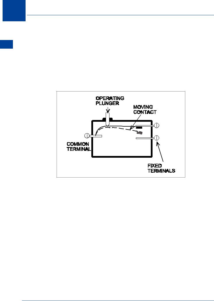
Microswitch
Microswitches are still used in modern aircraft to detect the position of a particular device e.g. door opened or closed.
The name Microswitch describes the small movement between the ‘make and break’ position. Microswitches can activate indications on the flight deck or control relays for a sequenced operation. They are largely replaced by proximity detectors on modern aircraft.
Figure 2.3 Microswitch
Bimetallic Switch (Thermal Switch)
Bimetallic switches are temperature sensitive switches and are activated when a certain value of temperature is reached to provide an indication to the pilot or to activate / deactivate a circuit, e.g. fire detection circuits, battery overheat switch, oil temperature warning light.
Proximity Detectors
Proximity detectors are electrical or electronic sensors that respond to the presence of a material. The electrical or electronic response is used to activate a switch, relay or transistor. There are many types of proximity detectors, the major types being inductive, capacitive and magnetic. The inductive and magnetic sensors need the monitored material to be metal, but the capacitive type can monitor either metal or non-metal materials.
InductiveType
This type of sensor has an inductance coil whose inductance changes when a ferromagnetic material (target) is brought into close proximity with it.
30
DC Electrics - Switches 2
Figure 2.4
This type of sensor is used in undercarriage systems in place of microswitches. A typical undercarriage system is described below. Each proximity switch consists of three components:
•A printed circuit card located in what is called the landing gear accessory unit.
•A sensor located on appropriate landing gear structure.
•An actuator (or target) for each sensor, located adjacent to its sensor.
The proximity sensor is a hermetically sealed unit, and is actuated by the presence of the actuator or target, i.e. it is not touched by it. As a result, the proximity switch is unaffected by atmospheric conditions, and is highly reliable.
CapacitiveType
In this type of sensor detection is made by a capacitor undergoing a capacitance change owing to the proximity of material.
The capacitive proximity detector is an extremely versatile device in that it is capable of detecting all materials, liquid and solid. As well as detecting the presence of a ferrous or nonferrous target, it can be used to detect high or low liquid levels in a hydraulic or fuel system.
MagneticType
A coil situated in a magnetic field will have an electromotive force (EMF) induced in it if the magnetic flux changes. The magnitude of the induced EMF will depend on the rate at which the flux is changed. These are the basic principles on which the magnetic proximity detectors operate.
In its simplest form, a coil is wound around a bar magnet and one pole of the magnet is then located close to a ferrous object. If the ferrous object moves, the flux in the magnet changes and an EMF is induced in the coil. If a number of ferrous objects move past the magnet, a train of pulses is induced in the coil.
31
2 DC Electrics - Switches
Switches - Electrics DC 2
Magnetic detectors are most commonly used in conjunction with mild steel gear wheels, each tooth in the wheel being, in effect, a ferrous object. The detector is located radially and close to the periphery of the wheel and provides an output having a frequency equal to the frequency of passage of the teeth past the detector.
Figure 2.5
Figure 2.6
32