

DC Electrics - Basic Principles 1
DC Electrics - Basic Principles 1
Figure 1.3 Comparison between voltage and water pressure
The source of the voltage can be a battery or a generator. Batteries become discharged as their voltage is used so are limited in their use. Generators are used to maintain a constant voltage.
For high and low voltages the following prefixes are used:
One Microvolt - one millionth of a volt (1 µV)
One Millivolt - one thousandth of a volt (1 mV)
One Kilovolt - one thousand volts (1 kV)
To measure voltage a voltmeter is used. It is connected across the two points between which the voltage is to be measured without disconnecting the circuit.
Current
The current (symbol I) in a conductor is the number of electrons passing any point in the conductor in one second and is measured in amperes or amps (symbol A).
Current can be measured by an instrument called an ammeter which is connected into the circuit so that the current in the circuit passes through the ammeter.
Small values of current are given the following prefixes:
One Microamp - one millionth of an ampere (1 µA)
One Milliamp - one thousandth of an ampere (1 mA)
Effects of an electric current:
•Heating Effect. When a current flows through a conductor it always causes the conductor to become hot - electric fires, irons, light bulbs and fuses.
•Magnetic Effect. A magnetic field is always produced around the conductor when a current flows through it - motors, generators and transformers.
•ChemicalEffect. When a current flows through certain liquids (electrolytes) a chemical change occurs in the liquid and any metals immersed in it - battery charging and electroplating.
5

1 DC Electrics - Basic Principles
Principles Basic - Electrics DC 1
Resistance
For a current to flow there must be a complete path or circuit. The fewer obstructions in the circuit the greater will be the current flow. The higher the voltage the greater will be the current flow.
The obstruction in the circuit which opposes the current flow is called resistance. Different materials have different numbers of free electrons those with more free electrons will have a lower resistance than those with few free electrons, so those with more free electrons are better conductors of electricity.
For a fixed voltage the smaller the resistance the larger will be the current flow and the larger the resistance the smaller will be the current flow. The current in the circuit can therefore be adjusted by altering the resistance.
Factors Affecting the Resistance
•Type of material. e.g. silver is a better conductor than copper
•Length. The longer the wire the greater the resistance
•Cross sectional area. The thicker the wire the smaller the resistance
•Temperature. The symbol for temperature coefficient is α(alpha). If resistance increases with an increase of temperature, the resistor is said to have a Positive Temperature Coefficient (PTC). If resistance decreases with an increase of temperature, the resistor is said to have a Negative Temperature Coefficient (NTC). Resistors having these characteristics are used in aircraft systems for temperature measurement.
Units of Resistance
The unit of resistance is the ohm (symbol Ω). A material has a resistance of one ohm if an applied voltage of one volt produces a current flow of one ampere.
For larger and smaller values:
One millionth of an ohm |
= |
one microhm (1 µΩ) |
One thousandth of an ohm |
= |
one milliohm (1 mΩ) |
One thousand ohms |
= |
one kilohm (1 kΩ) |
One million ohms |
= |
one megohm (1 MΩ) |
6

DC Electrics - Basic Principles 1
Resistors
Sometimes resistance is used to adjust the current flow in a circuit by fitting resistors of known value. These can be either fixed or variable and can be drawn like this:
Figure 1.4
Ohm’s Law
In a closed circuit there is a relationship between Voltage, Current and Resistance. If the voltage remains constant, any increase in resistance will cause a decrease in current and vice-versa (current inversely proportional to resistance).
If the resistance remains the same, any increase in voltage will cause an increase in current and viceversa (current directly proportional to voltage).
This is expressed as Ohm’s Law:
V = IR
And by transposition
I = VR or R = VI
Power
When a Force produces a movement then Work is said to have been done, and the rate at which work is done is called Power.
In an electric circuit work is done by the voltage causing the current to flow through a resistance, creating heat, magnetism or chemical action.
The rate at which work is done is called Power and is measured in Watts.
Watts (W) = Voltage (V) × Amperes (I)
DC Electrics - Basic Principles 1
7

1 DC Electrics - Basic Principles
Principles Basic - Electrics DC 1
Three formulae for calculating power can be derived from the two basic formulae V=IR and W=V×I
• |
Voltage unknown |
W = I2 R |
|||
• |
Resistance unknown |
W = V × I |
|||
• |
Current unknown |
|
V2 |
|
|
W = R |
|||||
|
|
||||
When a current passes through a resistor it becomes hot and will eventually melt if the current becomes excessive.
The amount of heat developed by a current (I) in a resistor (R) is I2R watts, therefore it can be seen that the heating effect is proportional to the square of the current. So a small increase in current can cause a significant increase in heating effect.
Each electrical component will be given a Power Rating (maximum wattage) which, if exceeded, will cause the component to overheat, e.g. 60 watt light bulb.
Each electrical circuit in an aircraft will be protected by a fuse or circuit breaker which will prevent the maximum power rating of a component to be exceeded by breaking the circuit if the current increases.
Series and Parallel Circuits
More than one resistance can be connected in any one circuit and they may be connected in Series - one after the other, or in Parallel - alongside each other.
• Series
Figure 1.5
Series connection reduces current flow and therefore power consumption, but can be impractical because individual loads (resistances) cannot be individually controlled. Also the failure of one resistance would mean failure of the rest of the circuit.
The total circuit resistance can be calculated by summing the individual resistances.
RT = R1 + R2 + R3 i.e. RT = 4 + 6 + 10
RT = 20 ohms
V = IR so current = 2012 = 0.6 amps
8
DC Electrics - Basic Principles 1
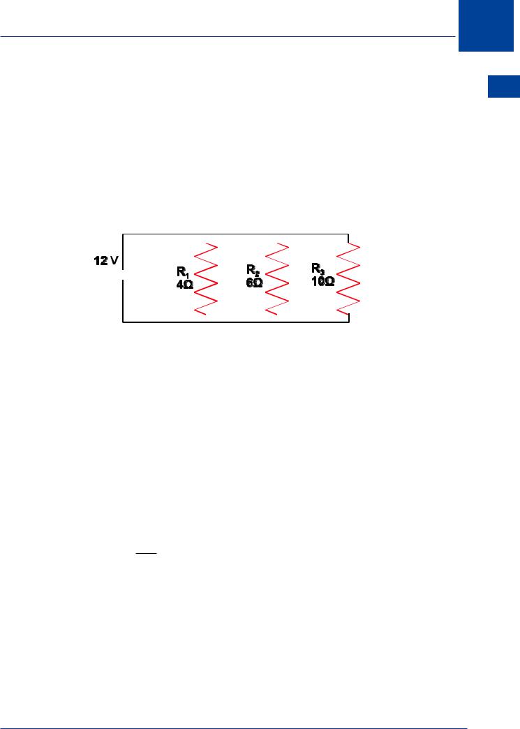
•Parallel
Parallel connection ensures each resistor is individually controllable and receives the same voltage. Failure of one resistor will not affect the others. Most aircraft loads are connected in parallel.
The total circuit resistance can be found by the following method.
1 |
= |
1 |
|
+ |
|
1 |
|
+ |
1 |
|
|
|
|||||||
R |
T |
R |
1 |
|
|
|
R |
2 |
R |
3 |
|
|
|
||||||
|
|
|
|
|
|
|
|
|
|
|
|
|
|
|
|||||
|
|
|
|
|
|
|
|
|
|
|
|
|
|
|
|
|
|
|
|
|
|
|
|
|
|
|
|
|
|
|
|
|
|
|
|
|
|
|
|
|
|
|
|
|
|
|
|
|
|
|
|
|
|
|
|
|
|
|
|
|
|
|
|
|
|
|
|
|
|
|
|
|
|
|
|
|
|
|
|
|
|
|
|
|
|
|
|
|
|
|
|
|
|
|
|
|
|
|
|
|
|
|
|
|
|
|
|
|
|
|
|
|
|
|
|
|
|
|
|
|
|
|
|
|
|
|
|
|
|
|
|
|
|
|
|
|
|
|
|
|
|
|
|
|
|
|
|
|
|
|
|
|
|
|
|
|
|
|
|
|
|
|
|
|
|
|
|
|
|
|
|
|
|
|
|
|
|
|
|
DC Electrics - Basic Principles 1
Figure 1.6
1 |
= |
1 |
+ |
1 |
+ |
1 |
||
R |
T |
|
4 |
6 |
10 |
|||
|
|
|
|
|
|
|
|
|
1 |
= |
15 + 10 + 6 |
|
|||||
R |
T |
|
|
60 |
|
|
|
|
|
|
|
|
|
|
|
|
|
1 |
= |
31 |
|
|
|
|
||
R |
T |
60 |
|
|
|
|
||
|
|
|
|
|
|
|
|
|
RT |
= |
60 |
|
|
|
|
||
|
|
|
31 |
|
|
|
|
|
RT = 1.94 ohms
V = IR so current = 1.9412 = 6 amps approx
9

1 DC Electrics - Basic Principles
• Combination of series and parallel resistors
Principles Basic - Electrics DC 1
Figure 1.7
First evaluate the parallel resistors then add the result to the series resistor.
1 |
= |
1 |
|
+ |
1 |
||||
R |
T |
10 |
|
6 |
|||||
|
|
|
|
|
|
|
|
|
|
1 |
= |
|
3 + 5 |
|
|
||||
RT |
30 |
|
|
||||||
|
|
|
|||||||
1 |
= |
|
8 |
|
|
|
|
||
RT |
30 |
|
|
|
|
||||
|
|
|
|
|
|||||
RT |
= |
30 |
|
|
|
|
|
||
8 |
|
|
|
|
|
||||
|
|
|
|
|
|
|
|
||
RT = 3.75 ohms
Find the lowest common denominator
Therefore the total resistance for the two parallel resistors is:
An alternative method of calculating the resistance of 2 resistors in parallel is:
RT |
= |
R1 |
× R2 |
|
R1 |
+ R2 |
|||
|
|
Using the above example
RT |
= |
10 × 6 |
|
||
|
10 + 6 |
|
|||
RT |
= |
60 |
|
RT = 3.75 ohms |
|
16 |
|
||||
10