

The Physics of Coronory Blood Flow - M. Zamir
.pdfPreface XIII
as for reading a draft of the book and o ering many valuable comments. I received valuable comments also from my friend and colleague Dr. Erik L Ritman, Professor of Physiology and Medicine at the Mayo Clinic College of Medicine, who kindly took time from his ever busy schedule to read the manuscript.
But the mission of this book was to be in Science and Engineering rather than in Pathology or Medicine. For many years I have been inspired by and learned enormously from the books of Professor Y.C. Fung who, in my eyes, is the father of biomechanics and of the notion that engineers should not only “dabble” in the mechanics of the cardiovascular system but should do so deliberately and with no apologies. His books on the subject exemplify this notion and have provided me with the inspiration to write a book in the same spirit. I am grateful to Professor Fung not only for this but for agreeing to read this book and to write the Foreword to it.
It was important for me to have the book scrutinized by experts on both sides of the divide, and I am grateful to three colleagues who were kind enough to plow through the analytical aspects of the book and the tedium of equations and algebra. Professor Guy Kember from the Department of Engineering Mathematics at Dalhousie University, Professor Matt Davison from the Department of Applied Mathematics at the University of Western Ontario, and Dr. Hope Alderson, formerly of the Department of Mathematics at the University of New Brunswick. I am indebted to all three for laboring tirelessly through the manuscript, particularly to Dr. Alderson who did so heroically with a baby in one hand and the manuscript in the other.
I am grateful to my friend and long-time aide, Mira Rasche, for technical help with the manuscript, and to the secretarial brigade in Applied Mathematics - Gayle McKenzie, Pat Malone, and Audrey Kager– for always being there. My deepest thanks go to my wife, Lilian, who may not share my enthusiasm for the subject, yet so willingly plowed through the manuscript and shared the burden in so many di erent ways. I am grateful to Dr. Elias Greenbaum, Editor-in-Chief of the Biological and Medical Physics, Biomedical Engineering Series, for his encouragement and continued support, and, at Springer NY, to David Packer and Lee Lubarsky for walking the manuscript to production, to MaryAnn Brickner for finally taking the manuscript away from my hands and setting the production wheels in motion, and to Frank McGuckin and Frank Ganz for helping with the nightmare of electronic typsetting.
M.Zamir
London, Ontario
February 7, 2005

Contents
Foreword . . . . . . . . . . . . . . . . . . . . . . . . . . . . . . . . . . . . . . . . . . . . . . . . . . . . . . VII
Series Preface . . . . . . . . . . . . . . . . . . . . . . . . . . . . . . . . . . . . . . . . . . . . . . . . . |
IX |
Preface . . . . . . . . . . . . . . . . . . . . . . . . . . . . . . . . . . . . . . . . . . . . . . . . . . . . . . . . XI
1 Static Design Issues . . . . . . . . . . . . . . . . . . . . . . . . . . . . . . . . . . . . . . . 1
1.1 The Lone Pump . . . . . . . . . . . . . . . . . . . . . . . . . . . . . . . . . . . . . . . . . 1
1.2 Heart “Disease”? . . . . . . . . . . . . . . . . . . . . . . . . . . . . . . . . . . . . . . . . 3
1.3 Origin of Coronary Blood Supply . . . . . . . . . . . . . . . . . . . . . . . . . . 5
1.4 Coronary Arteries . . . . . . . . . . . . . . . . . . . . . . . . . . . . . . . . . . . . . . . 7
1.5 Left/Right Dominance . . . . . . . . . . . . . . . . . . . . . . . . . . . . . . . . . . . 12
1.6 Branching Structure . . . . . . . . . . . . . . . . . . . . . . . . . . . . . . . . . . . . . 14
1.7 Underlying Design? . . . . . . . . . . . . . . . . . . . . . . . . . . . . . . . . . . . . . . 21
1.8 Coronary Flow Reserve . . . . . . . . . . . . . . . . . . . . . . . . . . . . . . . . . . . 27
1.9 Design Conflict? . . . . . . . . . . . . . . . . . . . . . . . . . . . . . . . . . . . . . . . . . 31
1.10 Summary . . . . . . . . . . . . . . . . . . . . . . . . . . . . . . . . . . . . . . . . . . . . . . . 32
2 Modelling Preliminaries . . . . . . . . . . . . . . . . . . . . . . . . . . . . . . . . . . . 35 2.1 Why Modelling? . . . . . . . . . . . . . . . . . . . . . . . . . . . . . . . . . . . . . . . . . 35 2.2 The “Lumped Model” Concept . . . . . . . . . . . . . . . . . . . . . . . . . . . . 37 2.3 Flow in a Tube . . . . . . . . . . . . . . . . . . . . . . . . . . . . . . . . . . . . . . . . . . 38 2.4 Fluid Viscosity: Resistance to Flow . . . . . . . . . . . . . . . . . . . . . . . . 41 2.5 Fluid Inertia: Inductance . . . . . . . . . . . . . . . . . . . . . . . . . . . . . . . . . 45 2.6 Elasticity of the Tube Wall: Capacitance . . . . . . . . . . . . . . . . . . . 56 2.7 Elasticity of the Tube Wall: Wave Propagation . . . . . . . . . . . . . . 62 2.8 Mechanical Analogy . . . . . . . . . . . . . . . . . . . . . . . . . . . . . . . . . . . . . 66 2.9 Electrical Analogy . . . . . . . . . . . . . . . . . . . . . . . . . . . . . . . . . . . . . . . 71 2.10 Summary . . . . . . . . . . . . . . . . . . . . . . . . . . . . . . . . . . . . . . . . . . . . . . . 75
XVI Contents
3 Basic Lumped Elements . . . . . . . . . . . . . . . . . . . . . . . . . . . . . . . . . . . 79 3.1 Introduction . . . . . . . . . . . . . . . . . . . . . . . . . . . . . . . . . . . . . . . . . . . . 79 3.2 RLC System in Series . . . . . . . . . . . . . . . . . . . . . . . . . . . . . . . . . . . . 81 3.3 Free Dynamics of the RLC System in Series . . . . . . . . . . . . . . . . . 84 3.4 R1,R2 in Parallel . . . . . . . . . . . . . . . . . . . . . . . . . . . . . . . . . . . . . . . . 88 3.5 R,L in Parallel . . . . . . . . . . . . . . . . . . . . . . . . . . . . . . . . . . . . . . . . . . 92 3.6 R,C in Parallel . . . . . . . . . . . . . . . . . . . . . . . . . . . . . . . . . . . . . . . . . . 97 3.7 RLC System in Parallel Under Constant Pressure . . . . . . . . . . . 101 3.8 RLC System in Parallel Under Constant Flow . . . . . . . . . . . . . . . 103 3.9 Summary . . . . . . . . . . . . . . . . . . . . . . . . . . . . . . . . . . . . . . . . . . . . . . . 112
4 Forced Dynamics of the RLC System . . . . . . . . . . . . . . . . . . . . . . 115
4.1 Introduction . . . . . . . . . . . . . . . . . . . . . . . . . . . . . . . . . . . . . . . . . . . . 115
4.2 The Particular Solution . . . . . . . . . . . . . . . . . . . . . . . . . . . . . . . . . . 116
4.3 Using the Complex Exponential Function . . . . . . . . . . . . . . . . . . . 117
4.4 Overdamped Forced Dynamics . . . . . . . . . . . . . . . . . . . . . . . . . . . . 119
4.5 Underdamped Forced Dynamics . . . . . . . . . . . . . . . . . . . . . . . . . . . 122
4.6 Critically Damped Forced Dynamics . . . . . . . . . . . . . . . . . . . . . . . 124
4.7 Transient and Steady States . . . . . . . . . . . . . . . . . . . . . . . . . . . . . . 126
4.8 The Concept of Reactance . . . . . . . . . . . . . . . . . . . . . . . . . . . . . . . . 131
4.9 The Concepts of Impedance, Complex Impedance . . . . . . . . . . . 137
4.10 Summary . . . . . . . . . . . . . . . . . . . . . . . . . . . . . . . . . . . . . . . . . . . . . . . 142
5 The Analysis of Composite Waveforms . . . . . . . . . . . . . . . . . . . . 145
5.1 Introduction . . . . . . . . . . . . . . . . . . . . . . . . . . . . . . . . . . . . . . . . . . . . 145
5.2 Basic Theory . . . . . . . . . . . . . . . . . . . . . . . . . . . . . . . . . . . . . . . . . . . 148
5.3 Example: Single-Step Waveform . . . . . . . . . . . . . . . . . . . . . . . . . . . 151
5.4 Example: Piecewise Waveform . . . . . . . . . . . . . . . . . . . . . . . . . . . . 157
5.5 Numerical Formulation . . . . . . . . . . . . . . . . . . . . . . . . . . . . . . . . . . . 164
5.6 Example: Cardiac Waveform . . . . . . . . . . . . . . . . . . . . . . . . . . . . . . 169
5.7 Summary . . . . . . . . . . . . . . . . . . . . . . . . . . . . . . . . . . . . . . . . . . . . . . . 174
6 Composite Pressure-Flow Relations . . . . . . . . . . . . . . . . . . . . . . . . 177 6.1 Introduction . . . . . . . . . . . . . . . . . . . . . . . . . . . . . . . . . . . . . . . . . . . . 177 6.2 Composite Pressure-Flow Relations Under Pure Resistance . . . 179 6.3 Example: Cardiac Pressure Wave . . . . . . . . . . . . . . . . . . . . . . . . . . 181 6.4 Composite Pressure-Flow Relations Under General Impedance 186 6.5 Composite Pressure-Flow Relations Under Inertial E ects . . . . 190 6.6 Composite Pressure-Flow Relations Under Capacitance E ects 198 6.7 Composite Pressure-Flow Relations Under RLC in Series . . . . . 207 6.8 Composite Pressure-Flow Relations Under RLC in Parallel . . . 213 6.9 Summary . . . . . . . . . . . . . . . . . . . . . . . . . . . . . . . . . . . . . . . . . . . . . . . 219
Contents XVII
7 Lumped Models . . . . . . . . . . . . . . . . . . . . . . . . . . . . . . . . . . . . . . . . . . . 221 7.1 Introduction . . . . . . . . . . . . . . . . . . . . . . . . . . . . . . . . . . . . . . . . . . . . 221 7.2 LM0: {R,C} . . . . . . . . . . . . . . . . . . . . . . . . . . . . . . . . . . . . . . . . . . . . 222 7.3 LM1: {R1,{R2+C}} . . . . . . . . . . . . . . . . . . . . . . . . . . . . . . . . . . . . . 229 7.4 LM2: {{R1+L},{R2+C}} . . . . . . . . . . . . . . . . . . . . . . . . . . . . . . . . . 235 7.5 LM3: {{R1+(pb)},{R2+C}} . . . . . . . . . . . . . . . . . . . . . . . . . . . . . . 241 7.6 Inflow-Outflow . . . . . . . . . . . . . . . . . . . . . . . . . . . . . . . . . . . . . . . . . . 249 7.7 Summary . . . . . . . . . . . . . . . . . . . . . . . . . . . . . . . . . . . . . . . . . . . . . . . 252
8 Elements of Unlumped-Model Analysis . . . . . . . . . . . . . . . . . . . . 255 8.1 Introduction . . . . . . . . . . . . . . . . . . . . . . . . . . . . . . . . . . . . . . . . . . . . 255 8.2 The Streamwise Space Dimension . . . . . . . . . . . . . . . . . . . . . . . . . 256 8.3 Steady Flow along Tube Segments . . . . . . . . . . . . . . . . . . . . . . . . . 258 8.4 Steady Flow Through a Bifurcation . . . . . . . . . . . . . . . . . . . . . . . . 265 8.5 Pulsatile Flow in a Rigid Tube . . . . . . . . . . . . . . . . . . . . . . . . . . . . 272 8.6 Pulsatile Flow in an Elastic Tube . . . . . . . . . . . . . . . . . . . . . . . . . . 279 8.7 Wave Reflections . . . . . . . . . . . . . . . . . . . . . . . . . . . . . . . . . . . . . . . . 287 8.8 Summary . . . . . . . . . . . . . . . . . . . . . . . . . . . . . . . . . . . . . . . . . . . . . . . 297
9 Basic Unlumped Models . . . . . . . . . . . . . . . . . . . . . . . . . . . . . . . . . . . 299 9.1 Introduction . . . . . . . . . . . . . . . . . . . . . . . . . . . . . . . . . . . . . . . . . . . . 299 9.2 Steady Flow in Branching Tubes . . . . . . . . . . . . . . . . . . . . . . . . . . 300 9.3 Pulsatile Flow in Rigid Branching Tubes . . . . . . . . . . . . . . . . . . . 307 9.4 Elastic Branching Tubes . . . . . . . . . . . . . . . . . . . . . . . . . . . . . . . . . . 313 9.5 E ective Impedance, Admittance . . . . . . . . . . . . . . . . . . . . . . . . . . 317 9.6 Pulsatile Flow in Elastic Branching Tubes . . . . . . . . . . . . . . . . . . 329 9.7 Cardiac Pressure Wave in Elastic Branching Tubes . . . . . . . . . . 343 9.8 Summary . . . . . . . . . . . . . . . . . . . . . . . . . . . . . . . . . . . . . . . . . . . . . . . 358
10 Dynamic Pathologies . . . . . . . . . . . . . . . . . . . . . . . . . . . . . . . . . . . . . . 361
10.1 Introduction . . . . . . . . . . . . . . . . . . . . . . . . . . . . . . . . . . . . . . . . . . . . 361
10.2 Magic Norms? . . . . . . . . . . . . . . . . . . . . . . . . . . . . . . . . . . . . . . . . . . 362
10.3 Coronary Heart Disease, Physical Exercise,
and the Conundrum of Coronary Flow Reserve . . . . . . . . . . . . . . 370
10.4 Wave Propagation Through a Coronary Bypass . . . . . . . . . . . . . 378
10.5 Wave Propagation Through a Coronary Stent . . . . . . . . . . . . . . . 381
10.6 Sudden Cardiac Death . . . . . . . . . . . . . . . . . . . . . . . . . . . . . . . . . . . 384
10.7 Broken Heart Syndrome . . . . . . . . . . . . . . . . . . . . . . . . . . . . . . . . . . 387
10.8 Summary . . . . . . . . . . . . . . . . . . . . . . . . . . . . . . . . . . . . . . . . . . . . . . . 388
References . . . . . . . . . . . . . . . . . . . . . . . . . . . . . . . . . . . . . . . . . . . . . . . . . . . . . 391
Index . . . . . . . . . . . . . . . . . . . . . . . . . . . . . . . . . . . . . . . . . . . . . . . . . . . . . . . . . . 403

1
Static Design Issues
1.1 The Lone Pump
There are approximately 1014 living cells within the human body, each needing to receive food (nutrients, metabolic products) and to dispose of waste products on an individual basis. The situation is not unlike that of the (somewhat lower, though equally overwhelming) number of humans on this planet, approximately 6× 10⁹ in this case, each needing to receive food and to dispose of waste products, again, on an individual basis. The cardiovascular system is responsible for bringing a line of supply and a line of return within reach of every living cell within the human body. These service lines are fully centralized, in the sense that they all originate from one location and all return to it. In the world analogy this would amount to having only one location for the dispatch of food for the entire world population, only one location for the return of all waste products, and a line of supply and one of return within reach of every individual on the planet.
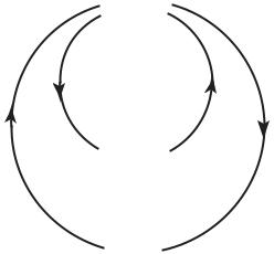
The cardiovascular system achieves this mammoth task within the human body not by storing food and waste products in one location, but by having them carried to and from every cell by a circulating fluid. The circulating fluid is blood, and the service lines along which it circulates are blood vessels. The central location which all lines of supply originate from and return to is not a massive warehouse but a small, very small, pump. The pump keeps the fluid in circulation (Fig.1.1.1). As it circulates, food is added to the fluid and waste products are extracted from it, on a continuing basis, somewhat in the manner of a conveyor belt.
The most important element of the cardiovascular system is therefore not so much the place where nutrients and metabolic products come from but the pump that circulates the fluid which carries these products. That pump is, of course, the heart. Circulation of blood that carries the food is as critical as the food itself because circulation keeps the food coming to the cells. Any disruption in that circulation is a disruption in food supply. Yes, life is not possible without blood, but in truth life is not possible without the circulation
2 1 Static Design Issues
HEART
pulmonary circulation
LUNGS
systemic circulation
BODY
Fig. 1.1.1. Circulation of a fluid medium makes it possible to meet the metabolic needs of several billion cells within the human body by means of only a small pump (HEART). Metabolic substances are carried by the fluid to and from cells in every part of the body (systemic circulation), and the fluid itself is reconditioned by a second circulation to and from the lungs (pulmonary circulation). Circulation of the fluid is therefore as critical as the metabolic goods which it carries. The pump must maintain both circulations at all times and without fail. There is no backup, no contingencies.
of blood. The heart is the pump that drives that circulation. It must pump at all times, which it does by contracting and relaxing in a rhythmic pattern, approximately once every second, more than 86 thousand times every day, and about 2 billion times in a lifetime of 75 years, nonstop. If it fails, the entire body is deprived of its lifeline and fails with it.
Is this a design error? Has nature made a mistake? We suspect not. The human cardiovascular system is highly evolved. Indeed, it has been observed that in the evolution of species the degree of complexity and sophistication of an organism goes hand in hand with the degree of complexity and sophistication of the metabolic system required to support it [119, 117, 118, 201]. We suspect, therefore, that far from there being any design error, the human cardiovascular system with its lone pump is fully tested. Yet questions about the wisdom of a lone pump linger, for when the system fails it does so in a catastrophic manner. There is an element of finality in its failure. There is no backup for the lone pump, no contingencies.
1.2 Heart “Disease”? |
3 |
1.2 Heart “Disease”?
While the heart, like other parts of the body, is subject to genetic disorders and infectious diseases [179], only a very small proportion of heart failures in the developed world are caused by such conditions. In all other cases a lack of blood supply to the heart muscle, or a lack of fuel which the muscle needs for doing its pumping work, is the principal cause of heart failure [83, 206, 14].
Yet, “heart disease” is the term most widely used in association with heart failure. The term is somewhat misleading because it suggests that the failure is due to a disease of the heart itself which, as stated above, occurs in only a very small proportion of cases. The situation is analogous to using the term “malfunction” to describe a car engine failure caused by lack of fuel. Terms that are less commonly used but that are somewhat more accurate are “coronary heart disease” and “coronary artery disease”, both at least hinting at a problem in the lines of blood supply to the heart.
In this book the term “heart disease” shall be reserved for only the small proportion of cases where the heart is diseased in the true sense of a genetic or infectious disorder. In all other cases the term “heart failure” shall be used instead, to mean failure of the heart as a pump caused by lack of blood supply. The lack of blood supply may be the immediate cause of heart failure as in the case of a thrombus or an embolus, or it may be the precipitating factor as in the case of myocardial infarction.
It is appreciated that this usage of the terms “heart disease” and “heart failure” di ers from common usage of these terms in the clinical setting. The intention here is to emphasize the strictly biomedical engineering view of the coronary circulation to be adopted in this book. According to this view, blood supply to the heart is provided by a highly dynamic system which can be disrupted by not only a problem in the lines of supply but also by a disturbance in the dynamics of the system. Indeed, the dynamics of blood supply to the heart are the principal subject of this book.
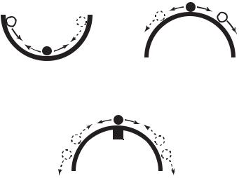
The complication, of course, is that the organ responsible for blood supply to the heart is the heart itself. When the heart fails, it fails to provide blood supply to not only every other part of the body but to itself, too. The situation has the elements of a control system with positive feedback. In such a system, a small failure produces a signal which leads to more failure, while in a system with negative feedback, a small failure produces a corrective signal which leads to less failure. The second system is regarded as stable and the first unstable, in the sense that after a small departure from equilibrium the second system can recover and return to equilibrium while the first cannot. A small steel ball at the bottom of a big bowl constitute a stable system, but if the bowl is turned upside down and the steel ball is positioned precariously at its peak, the system becomes unstable (Fig.1.2.1).
On the face of it, it would seem that the system of blood supply to the heart is an unstable system, since a small failure of the heart muscle would reduce its ability to pump which in turn would reduce blood supply to every
41 Static Design Issues
(a) |
|
(b) |
|
|
|
|
|
|
(c)
Fig. 1.2.1. Stability of coronary blood supply. Blood supply to the heart is provided by the heart itself: Does heart failure, therefore, lead to more failure? Shown here is the analogy of a small steel ball in equilibrium at the bottom of a large bowl (a). A small departure from equilibrium in this case is corrected by a negative signal which acts to move the ball back towards its neutral position. If the bowl is turned upside down as in (b), however, and the ball is positioned precariously at the peak, a small departure from equilibrium produces a positive signal which moves the ball yet further away from the peak. Regulatory mechanisms in coronary blood flow ensure that a small reduction in blood supply to the heart muscle does not lead to further reduction. In the bowl analogy it is as if a small magnet is placed under the bowl’s peak as in (c), so that a small departure of the ball from the peak is corrected by the pull of the magnet. But if blood supply is prevented from reaching the heart muscle because of coronary artery disease, this mechanism becomes less e ective or inoperative. In the bowl analogy it is as if the magnet is contaminated and can no longer pull back the ball e ectively.
part of the body, including the heart muscle itself. But the situation is not in fact as precarious as the steel ball at the top of the upside-down bowl. Regulatory mechanisms in coronary blood flow (autoregulation) ensure that a reduction in the ability of the heart to pump does not translate immediately into a reduction of blood supply to the heart itself [83, 128, 136, 100, 183]. This mechanism provides a local reprieve and allows recovery to occur. In the bowl analogy it is as if a magnet is placed under the peak of the upside-down bowl, so that a small excursion of the steel ball away from the peak is corrected by the magnet pull before the situation becomes beyond recovery (Fig.1.2.1).
This issue does not usually play a key role in heart failure because, in the overwhelming majority of cases, the cause of a reduction in blood supply to
1.3 Origin of Coronary Blood Supply |
5 |
the heart muscle is not a reduction in the innate ability of the heart muscle to pump but a gradual occlusion or sudden blockage of some of the vessels that carry this supply to the heart, caused in turn by a disease process within the vessels. Thus, heart failure (as defined in this book) is not usually mediated by positive feedback but by a direct reduction of blood supply to the heart muscle, which is not triggered by failure of the muscle to pump in the first place. The recovery mechanism that compensates for the reduction in blood supply to the heart muscle is thus disrupted because of an inability of blood supply to reach the heart. In the bowl analogy it is as if the magnet is contaminated and its ability to bring the steel ball back to the neutral position is diminished. “Heart disease” does not fairly describe the situation in hand, “heart starvation” would be a more accurate term. As stated earlier, the term “coronary heart disease”, used less often, is somewhat more accurate in that it hints at the involvement of the coronary arteries, while “coronary artery disease” is yet more accurate because it places the problem precisely where it belongs.
1.3 Origin of Coronary Blood Supply
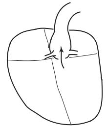
As a pump, the heart consists of four chambers, two ventricles and two atria, which contract and relax rhythmically. The two ventricles eject blood and the two atria act as receiving chambers for returning blood [133]. Output from the left ventricle is carried by the aorta to every part of the body, then returns to the right atrium, thus producing the so-called “systemic circulation” (Fig.1.1.1). Output from the right ventricle is carried by the pulmonary artery to the lungs where blood is oxygenated and then returned to the left atrium, constituting the “pulmonary circulation” [48].
The two systems must clearly operate in tandem to avoid accumulation (congestion) of fluid proximal to or in any of the four chambers. That is, on average, the systemic and pulmonary circulations must move the same volume of blood per cardiac contraction (Fig.1.1.1). However, the systemic circulation operates at a much higher pressure than the pulmonary, hence the work performed by the two ventricles is not the same. The pumping power produced by the left ventricle and hence its metabolic requirements are considerably higher than those of the right ventricle [135, 141]. Accordingly, the muscular walls of the left ventricle are the main focus of blood supply to the heart. While blood supply must reach every part of the heart for the organ to remain viable, blood supply to the left ventricle dominates coronary blood flow because of its intense requirements.
While the four chambers of the heart contain blood at all times, and while the left ventricle contains oxygenated blood ready for distribution to every part of the body, this blood must leave the heart before it can be tapped to supply the heart itself. The reason for this is that most cardiac cells, like those in other parts of the body, are served by a system of capillaries which are fed, ultimately, by a supply line from the aorta [199]. As it traverses the
6 1 Static Design Issues
AO
RA |
LA |
LCA
RCA
RV |
LV |
Fig. 1.3.1. Origin of blood supply to the heart. As the aorta (AO) leaves the left ventricle (LV) with oxygenated blood for every part of the body, its first two branches, the so-called left main and right coronary arteries (RCA, LCA), are destined to serve the heart itself. The figure is highly schematic, to show functional topology only.
body the aorta gives rise to many branches, destined to di erent parts of the body or to specific organs [48]. Each organ or territory within the body has its own supply line from the aorta, followed by a vascular tree structure to reach di erent parts of the organ or territory, and a system of capillaries to reach every cell. The heart is served in the same manner [81].
It would seem appropriate, therefore, that as the aorta leaves the left ventricle, laden with oxygenated blood for every part of the body, its first two branches are destined to serve the heart itself (Fig.1.3.1). They are known as the left main and right coronary arteries [133, 228, 216]. While this may seem as if the heart is being given “first priority”, it is more likely the result of physical proximity of the heart to the root of the aorta (Fig.1.3.1).
Not infrequently, more than two coronary branches arise at the root of the aorta to bring blood supply to the heart (Fig.1.3.2), but in most cases only two are prominent and serve the role of the left and right main coronary arteries. Additional branches are usually considerably smaller than the main two and make only a local contribution to coronary blood supply. In rare cases only one supplying artery may arise from the aorta, and in yet others a supplying artery may not arise directly from the aorta but from one of its branches. The range and frequency of these and other variations have been well studied and documented [94, 69, 16, 146, 127, 61, 73, 196, 133, 182, 81, 152].