

Multidimensional Chromatography
.pdf18 |
Multidimensional Chromatography |
2.2TRANSFER TECHNIQUES
This chapter will describe some of the direct transfer techniques used for both normal phase and reversed phase eluents. An overview of the various techniques (direct and indirect) for the analysis of water or water-containing eluents will also be given. In fact the nature of the eluent greatly influences the choice of the transferring technique, as will be explained in the discussion for each section. Figure 2.1 summarizes the concepts of eluent evaporation (with some subclasses), thus allowing the transfer of large LC fractions to the gas chromatograph.
2.2.1RETENTION GAP TECHNIQUES
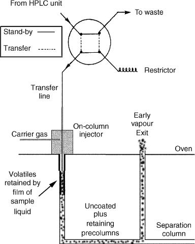
The retention gap method (1, 2) represents the best approach in the case of qualitative and quantitative analysis of samples containing highly volatile compounds. The key feature of this technique is the introduction of the sample into the GC unit at a temperature below the boiling point of the LC eluent (corrected for the current inlet pressure), (see Figure 2.2). This causes the sample vapour pressure to be below the carrier gas inlet pressure, and has two consequences, as follows:
•volatile components are reconcentrated by the solvent effects, primarily solvent trapping (3);
•the high-boiling compounds are spread by band broadening in space.
A layer of condensed eluent is built up ahead of the evaporation site which acts as a thick layer of retaining stationary phase, thus blocking the further movement of all but the most volatile compounds into the column. Solvent evaporation, therefore proceeds from the rear towards the front of the sample layer (see Figure 2.2).
These effects refer to the reconcentration obtained with an uncoated inlet. In fact, the term retention gap means a column inlet of a retention power lower than that of the analytical column. This retention gap is placed in front of the analytical column, thus allowing different reconcentration mechanisms to occur.
Together with this solvent effect, another effect, called phase soaking, occurs in the retention gap technique: if a large volume of solvent vapour has saturated the carrier gas, the properties of the stationary phase can be altered by swelling (thicker apparent film), a change in the viscosity or changed polarity. The consequence is that the column shows an increased retention power, which can be used to better retain the most volatile components.
During the evaporation process, band broadening in space spreads the highboiling compounds. Two retention gap effects can reconcentrate the bands, namely phase-ratio focusing and cold trapping, generally known as stationary phase focusing effects.
Phase ratio focusing is based on the higher migration speed of components through the retention gap compared to that through the analytical column. Reconcentration depends on the ratio between the retention power in the preand in

Coupled HPLC with HRGC |
19 |
Figure 2.1 LC – GC transfer techniques.
20 |
Multidimensional Chromatography |
the main column. Cold trapping occurs when the solutes reach an analytical column which is maintained at a temperature too low for them to migrate, so they accumulate and concentrate until the oven temperature is increased sufficiently to allow them to move through the column.
Figure 2.2 Schematic representation of an on-column interface. The eluent leaving the HPLC detector enters the valve and in the stand-by position, leaves it to go to waste. When the valve is switched on, the eluent is pumped through the transfer line into the inlet of the oncolumn injector. The liquid floods the capillary wall, thus creating a layer that will retain the solutes. Evaporation occurs from the rear part of the solvent so refocusing the chromatographic band. At the end of the transfer, the valve is switched off, and the eluent again flows to waste.
Coupled HPLC with HRGC |
21 |
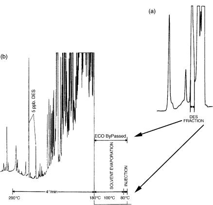
The retention gap technique, due to the solvent effects explained above, allows the analysis of compounds eluting immediately after the solvent peak. The limitation of this technique is the need for long retention gaps and long analysis times, since the solvent has to be completely evaporated prior to starting the elution of components of interest. It is possible to find in the literature many applications which use the classical retention gap for the transfer from HPLC to HRGC. In particular, Figure 2.3 (a)
(4) shows the LC chromatogram of a bovine urine sample after formation of the dipentaflorobenzyl ether of diethylstilbestrol (DES), which is a synthetic estrogen.
Figure 2.3 (a) LC chromatogram of a bovine urine sample of DES carried out on a 100 3 mm id glass column, packed with 5 m silica gel Spherisorb S-5-W, with cyclohexane/1% THF as eluent at a flow rate of 260 l/min. (b) GC – ECD (electron-capture detector) chromatogram of the transferred fraction coming from a urine sample spiked with 5 ppb of DES (two isomers). Reprinted from Journal of Chromatography, 357, K. Grob et al., ‘Coupled HPLC–GC as a replacement for GC–MS in the determination of diethylstil bestrol in bovine urine’, pp 416 – 422, copyright 1986, with permission from Elsevier Science.
22 |
Multidimensional Chromatography |
Transfer of an LC fraction of 300 l volume occurred by the conventional retention gap technique. In fact, Figure 2.3(b) shows the GC chromatogram obtained after the transfer of the LC fraction.
An additional technique, called ‘partially concurrent eluent evaporation,’ has been introduced in order to overcome some drawbacks of the retention gap technique. In this case, a large amount of solvent is evaporated during introduction (concurrently), yet still producing a zone flooded by the eluent, thus providing solvent trapping (5). This technique allows the use of shorter retention gaps or larger transfer volumes. In theory, an early vapour exit (6) should be placed between the uncoated precolumn and the main column, but in practice a short section of the main column (7) is placed between the precolumn and the vapor exit, so rendering the closure of the vent less critical.
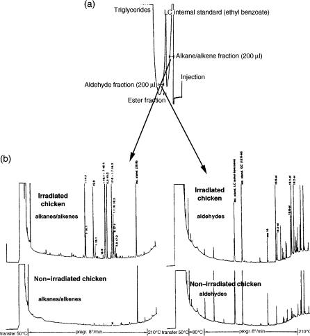
In particular, Figure 2.4(a) (7) shows the LC chromatogram of fat extracted from an irradiated chicken. Irradiation of foods containing fat produces radiolysis fragments of triglycerides, such as acids, propanediol esters, alkenes, aldehydes and methyl esters. The alkane/alkene fraction transferred to the gas chromatograph correspond to the first 200 l eluted after the dead volume. The second fraction of interest was that of the aldehydes, eluted after a few minutes. The two fractions (Figure 2.4(b)), both of about 200 l, were transferred by partially concurrent eluent evaporation by using a precolumn of 12 m 0.50 mm id, with a 3 m 0.32 mm id fused silica section of the separation column serving as a retaining precolumn before the solvent vapour exit.
2.2.2 LOOP-TYPE INTERFACES (CONCURRENT ELUENT EVAPORATION)
The retention gap techniques, essential for the analysis of very volatile components, are often replaced by concurrent eluent evaporation techniques, due to their simplicity and the possibility of transfering very large amount of solvent. In this case, the solvents are introduced into an uncoated inlet at temperatures at or above the solvent boiling point.
In this way, the liquid can be transferred at a speed corresponding to the evaporation speed. The fraction to be analysed is contained in a loop (see Figure 2.5), connected to a switching valve. By opening the valve, the sample in the loop is driven by the carrier gas into the GC unit (8), instead of the LC pump. An early vapour exit is usually placed after a few metres of the deactivated precolumn (9) and a short piece (3 – 4 m) of the main column (retaining precolumn). This valve is opened during solvent evaporation in order to reduce the amount of solvent that would reach the detector, and at the same time, to increase the solvent evaporation rate (6).
When the sample solvent evaporates at the front end of the liquid, volatile compounds co-evaporate with the solvent and start moving through the main column. In this way, volatile components can be lost through the early vapour exit or, if venting is delayed, the most volatile compounds reach the detector even before the end of
Coupled HPLC with HRGC |
23 |
Figure 2.4 (a) LC chromatogram of fat extracted from an irradiated chicken. The alkane/alkene and the aldehyde fractions (200 m each) were transferred to the GC unit in order to determine the effects of irradiation. (b) GC chromatograms of the fractions transferred of a non-irradiated and an irradiated chicken dose of 5 KGY. Reprinted from Journal of High Resolution Chromatography, 12, M. Biedermann et al., ‘Partially concurrent eluent evaporation with an early vapor exit; detection of food irradiation through coupled LC – GC analysis of the fat’, pp. 591 – 598, 1989, with permission from Wiley-VCH.
solvent evaporation. In practice, the first properly shaped peaks are eluted at temperatures only 40 – 120 °C above the transfer temperature.
The main advantages of this technique are that short retention gaps are sufficient (3 – 20 m), the evaporation rate is faster than that obtained with transfers at a temperature below the boiling point of the solvent, and the requirement that solvent

24 |
Multidimensional Chromatography |
Figure 2.5 Schematic representation of a loop-interface scheme for concurrent eluent evaporation. The sample is first loaded in a loop and then, after switching the valve, directed by the carrier into the GC column. The solvent evaporates from the front end of the liquid, thus causing band broadening. Since the column is not flooded, very large amount of liquid can be introduced.
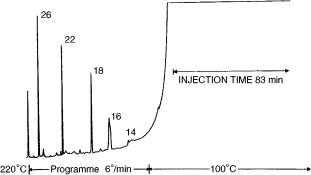
wets the retention gap is less important. Since its first reported use in 1985 (10), this technique has been largely used for the analysis of sterols, waxes, higher aliphatic and triterpene alcohols, contaminants of water and foods products, and fuel products. Figure 2.6, for example, shows the results of transferring a 10ml volume of n- hexane containing C 1 4 – C26 alkanes (about 1 ppb each) (8), introduced at a rate of 120 l/ min through an on-column interface under conditions of concurrent eluent evaporation.
Coupled HPLC with HRGC |
25 |
Figure 2.6 Gas chromatogram of a 10 ml test sample containing C 1 4 –C26 alkanes in n-hexane (about 1 ppb each): the carrier gas (H2) inlet pressure was 2.5 bar for a 22 m 0.32 mm id separation column coupled with a 2 m 0.32 mm id uncoated precolumn (no vapour exit). Reprinted from Journal of High Resolution Chromatography, 9, K. Grob et al.,
‘Concurrent solvent evaporation for on-line coupled HPLC – HRGC’, pp. 95 – 101, 1986, with permission from Wiley-VCH.
The main drawback of this technique is represented by the loss of volatile compounds. A solution to this problem is represented by the so-called co-solvent trapping technique used during concurrent eluent evaporation. In practice, a small amount of a higher boiling co-solvent is added to the main solvent at such a concentration that some co-solvent is left behind as a liquid, while some is co-evaporated with the main solvent. The co-solvent remaining forms a barrier of liquid film, which evaporates from the rear to the front, as in the retention gap technique. Volatile components are retained by the solvent trapping effect, and released when the evaporation of the co-solvent is completed. Although this technique shows some similarities to the retention gap technique, the main difference is represented by the interface used: the latter technique uses an on-column interface, while concurrent eluent evaporation is designed for a loop-type interface.
While partially concurrent eluent evaporation is easier to use, and is preferred for the transfer of normal phase solvents, concurrent eluent evaporation with co-solvent trapping is the technique of choice for transfer of water-containing solvents, because wettability is not required.
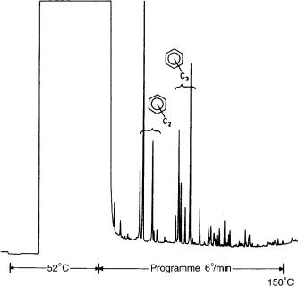
Figure 2.7 (11) shows a gas chromatogram obtained by co-solvent trapping and concurrent eluent evaporation after injecting 500 l of diluted gasoline. The main solvent was n-pentane with 5% of n-heptane as co-solvent. It is noteworthy that without the co-solvent, higher-boiling compounds could be lost.
2.3VAPORIZATION WITH HOT INJECTORS
Together with the techniques described above, other techniques using hot injectors for the transfer of large-volumes in capillary gas chromatography have been developed. Transfer of large-volume solvents in a programmed temperature vaporizing
26 |
Multidimensional Chromatography |
Figure 2.7 Gas chromatogram obtained for 500 l of diluted gasoline in n-pentane introduced by concurrent eluent evaporation, using n-heptane as the co-solvent. Reprinted from
Journal of High Resolution Chromatography, 11, K. Grob and E. Müller, ‘Co-solvent effects for preventing broadening or loss of early eluted peaks when using concurrent eluent evaporation in capillary GC. Part 2: n-heptane in n-pentane as an example’, pp. 560 – 565, 1988, with permission from Wiley-VCH.
(PTV) injector is carried out by opening the split valve during the transfer of the fraction. An additional purge time is used to remove the remaining solvent from the bed. The solvent is selectively eliminated, while the solutes are retained on the packing material. When solvent evaporation is concluded, the split line is closed before the chamber is heated, thus allowing splitless transfer of the solutes into the column. PTV, with solute trapping in packed beds, can be successfully applied to the transfer of large volumes, although this method does present some disadvantages. The main problem of injecting into a hot vaporising chamber occurs when thermally labile compounds need to be analysed. In fact, the temperature of the injector would decrease due to the large amount of solvent evaporating inside the chamber, and therefore higher temperatures are necessary. Moreover, since the packed bed has a high retention power, the chamber has to be heated above the column temperature in order to release the solutes. However, this technique shows some advantages when compared to the techniques that use uncoated precolumns for large sample introduction. First, wettability is not important for the retention of the liquid, and secondly, the packing materials used for the liners are more stable than deactivated silica tubing. In addition, packed beds retain more liquid per unit internal volume and the
Coupled HPLC with HRGC |
27 |
PTV chamber is more easily heated than a capillary column. The introduction of large volumes with the use of such an injector in solvent-split mode was first investigated in the 1970s. Staniewski, Cramers and co-workers (12–17) demonstrated that by reducing the injector temperature and by increasing the purge gas during the solvent elimination it was easier to remove solvent, and showed that by using chambers packed with porous glass beads instead of Tenax TA or Thermotrap recovery of solutes may be improved.
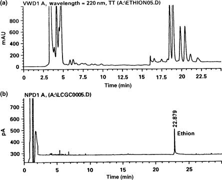
A different approach was recently introduced by Sandra and co-workers. (18, 19) for the transfer of large volumes from a liquid chromatograph, to a gas chromatograph. This interface consist of a flow cell that was made by modifying an autosampler vial. The solvent coming from the HPLC unit which contains the solutes is continuously sampled by the flow cell. When the fraction of interest is inside the vial, a large-volume injection is made using the PTV device in the solventvent mode. This technique was successfully applied to the analysis of pesticides, as shown in Figure 2.8 (19).
Figure 2.8 (a) HPLC fractionation of orange oil on Lichrosorb 100 diol. (b) LC – GC-NPD analysis of peel orange oil (from Florida), contaminated with ethion. Reprinted from Proceedings of the 20th International Symposium on Capillary Chromatography, F. David et al., ‘On-line LC – PTV – CGC: determination of pesticides in essential oils’, 1998, with permission from Sandra P.