

Micro-Cap v7.1.6 / Ug
.pdfSelection
Single objects or entire regions may be selected for editing, deleting, moving, rotating, mirroring, stepping, or copying. They may be selected or deselected individually or as a group. Clicking on an object or region while the SHIFT key is down toggles the selection state. If the object or region was formerly selected, it becomes deselected. If it was formerly deselected, it becomes selected.
To illustrate, press the SHIFT key and hold it down. Click on the Q7 transistor in the selected group. Be careful not to click on the name Q7 as that will select the PART attribute rather than the part itself. Release the SHIFT key and the circuit lookslikethis:
Figure 3-15 Partial selection using SHIFT + mouse click
The left transistor is now deselected. If you press the Del key, the transistor will remain but the rest of the selected region will be deleted. Press the SHIFT key and click the same transistor and it is again selected. If you now press the Del key, the entire selected region will be deleted.
By using partial selection, virtually any subset of a schematic can be selected for editing, copying, deleting, or moving.
To complete this part of the tutorial, click on the Revert option from the File menu to restore the DIFFAMP circuit.
75

Drag copying
Ordinarily, when you drag a selected object or group of objects, the entire group moves with the mouse. However, if you hold down the CTRL key while you drag, MC7 leaves the original selected objects in place, makes a copy, and drags the copy along with the mouse. It's like tearing off a sheet from a pad of printed copies. As with stepping and clipboard pasting, the part names are incremented. Grid text is incremented only if the Options / Preferences / Common Options / Text Increment option is enabled.
To illustrate with the DIFFAMP circuit, click on the Select button, and drag a region box around the V2 battery at the upper right. Release the button. Press CTRL. Click within the selected region and drag it to the right. Notice that a copy of the selected region is created as shown below.
Figure 3-16 Drag copying
Drag copying is usually more convenient than clipboard cut and paste when you need to make only one copy. Its one step operation is easier and simpler to use than copying and pasting from the clipboard.
If you plan to paste more than one copy, then copying and pasting from the clipboard is usually faster.
76 Chapter 3: Creating and Editing Simple Circuits
Pan means to move the window view.
Navigating large schematics
How do you navigate a large a schematic?
1. Panning: This is by far the easiest method. To mouse pan, drag the right mouse button. It's like sliding a piece of paper across a desktop. Keyboard panning uses CTRL + <any cursor key> to move the view in the direction of the arrow.
2.Scroll bars: Use the schematic scroll bars. This is slow but sure.
3.Relocation: Use the SHIFT + click method to relocate and change views. While holding down the SHIFT button, click the right mouse button where you want the window centered. Clicking toggles the scale between high and low magnification and centers the schematic at the mouse position.
4.Use the Page scroll bar if the desired area is on another page or use CTRL + PAGE UP and CTRL + PAGE DOWN to navigate the pages.
5.Place flags where desired using the flag mode  button. Then select a flag from the list by clicking on the Go To Flag
  button.
6.Use the Zoom-Out  or Zoom-In
  buttons in the Tool bar.
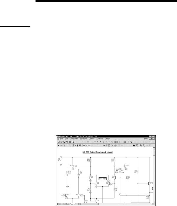
Figure 3-17 The UA709 circuit
77
To illustrate these methods, load the circuit UA709. It looks like Figure 3-17. At a resolution of 600 X 800, it's too large to see at the default scale, so shrink its scale by clicking twice on the Zoom-Out button. At this scale the circuit looks like this:
The Zoom-In button increases the image size
The Zoom-Out button decreases the image size
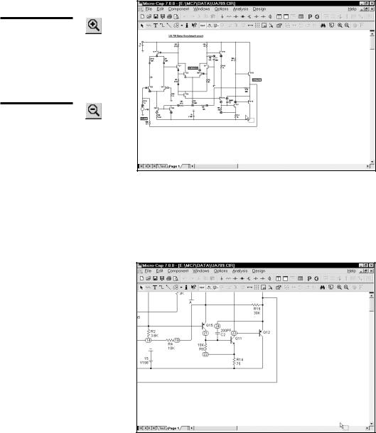
Figure 3-18 After clicking the Zoom-Out button
Simultaneously press the SHIFT key and click the right mouse button in the lower right, near the two transistors. This centers the schematic at the mouse position and redraws it at normal scale.
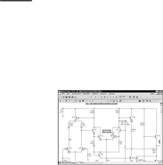
Figure 3-19 The UA709 after repositioning
78 Chapter 3: Creating and Editing Simple Circuits
Panning uses the keyboard cursor keys or a right button mouse drag to move the schematic.
Another SHIFT + click redraws the circuit at the low magnification scale. A final SHIFT + click near the upper left corner returns the schematic to 1:1 scale.
Panning is probably the easiest and most powerful method of moving around most schematics. To pan, drag anywhere on the schematic using the right mouse button. While holding the button down, drag the mouse and move the schematic. When the mouse is at or near a window edge, release the mouse button. Repeat the procedure until the schematic is in the desired position. Pan the UA709 circuit by clicking near the center and dragging left. This moves the schematic to the left, exposing more of the right-hand portion.
Finally, you can use flags to navigate the schematic. This method is most useful for very large schematics where panning might take many attempts to span the entire schematic. In this method you place flags in the schematic where you expect to want to visit in the future. Then simply picking the flag from the list centers the schematic view around the selected flag. To illustrate, click on the Go To
Flag  button or select Edit / Go To Flag. Select the 'DIFFPAIR' flag from the list. This redraws the schematic, centered on the flag, as shown below.
Figure 3-20 Navigating with flags
Close the UA709 file without saving it.
79

Creating and editing SPICE text files
MC7 can create and analyze SPICE text file circuit descriptions as well as schematics. SPICE text files may be created externally with a word processor or text editor, or internally using the MC7 text editor. To illustrate the procedure for creating a text file, select the New option from the File menu. This presents a dialog box where you specify the type of file to create. Click on the SPICE/Text option, then on the OK button. This opens a new text window and positions the text cursor at the upper left.
Type in the following:
CHOKE.CKT
V1 1 0 SIN (0 100 50)
V2 0 3 SIN (0 100 50)
D1 1 2 DIO
D2 3 2 DIO
L1 4 2 5
R1 0 2 10K
R2 0 4 10K
C1 0 4 2UF
.MODEL DIO D (IS=1E-14 CJO=10PF)
.TRAN .2m 0.05 0 .2m
.TEMP 27
.PLOT TRAN V(1) V(2) V(3) V(4) -150,200
.END
Save the circuit under the name CHOKE1.CKT using the Save As option from the File menu. Note that SPICE circuit file names do not require or assume an extension. There is no default extension. Any extension except "CIR" can be used. The "CIR" extension is reserved for schematic files. By convention, MC7 uses "CKT" for SPICE files, but any extension, except "CIR", will do.
New SPICE/Text files are created in the same way as schematics, by using the New command from the File menu.
80 Chapter 3: Creating and Editing Simple Circuits
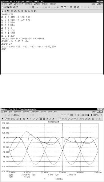
Figure 3-21 The sample SPICE circuit
Your circuit should look like Figure 3-21. Press ALT + 1 to run a transient analysis. When the Analysis Limits dialog box is displayed, press F2 to run the analysis. The results should look like Figure 3-22.
Figure 3-22 Transient analysis of the SPICE circuit
After the analysis the program automatically determines suitable scales if needed and plots the requested waveforms as specified in the .PLOT statement.
Exit the analysis by pressing F3, then close the file with CTRL + F4.
81

Summary
The most important ideas and methods covered in this chapter are:
•To open a new schematic use the New item on the File menu, or use the one automatically opened when the program first starts.
•Change the default component if it is different from the one you want to add. Default components are selected from the Component menu, a Component palette, or one of the part buttons in the Tool menu.
•To add a component, press CTRL + D or click the Component mode button. Select the component you want from the Component menu, User palette, or Tool bar button. Click the mouse on the schematic and drag it into place. If necessary, change its orientation with the right mouse button.
•Press CTRL + W or click the Wire item in the Tool bar to add wires.
•Components are connected with wires. To add a wire, click at one endpoint, drag the mouse to the other endpoint, then release it. Crossing wires do not connect.
•Press CTRL + T or click the Text button in the Tool bar to add text.
•Add text to nodes to name them for easy reference or use the node numbers. Nodes with the same name are connected.
•To edit, move, copy to the clipboard, or delete an object, it must first be selected. To select an object, press CTRL + E to enter the Select mode, then click the object. To select a region, drag the mouse over the region. Use SHIFT + click to deselect an object in a selected group.
•Selected objects are copied to the clipboard with CTRL + C and pasted to the cursor location with CTRL + V.
•CTRL + drag copies and renames selected objects.
•Navigating a schematic is done by scrolling, panning, changing the scale, positioning with SHIFT + click, using flags, and page scrolling.
82 Chapter 3: Creating and Editing Simple Circuits

Chapter 4 |
TransientAnalysis |
What's in this chapter
Transient analysis is the topic of this chapter. Using the MIXED4 circuit, the capabilities of the time domain simulator are explored. The goal is to introduce and build a sound understanding of these basic subjects:
•Controlling the analysis through the Analysis Limits dialog box
•Selecting curves to plot or print
•
•
State variables and initialization
State Variables editor
83

The Transient Analysis Limits dialog box
Load the MIXED4 circuit file and select Transient from the Analysis menu. MC7 extracts the necessary circuit information directly from the schematic. More information is needed before the analysis can begin, and that information is supplied by the Analysis Limits dialog box.
Command buttons |
|
Numeric limits |
Options |
|
Curve options
Expressions
Variables list
Command buttons
Figure 4-1 The Analysis Limits dialog box
The Analysis Limits dialog box has five main areas: Command buttons, Numeric limits, Curve options, Expression fields, and Options.
The Command buttons, located just above the Numeric limits field, contain seven commands.
Run: This command starts the analysis run. Clicking the Tool bar Run button  or pressing F2 will also start the run.
Add: This command adds another Curve options field and Expression field line after the line containing the cursor. The scroll bar to the right of the Expression field scrolls through the curves when there are more than
can be displayed.
Delete: This command deletes the Curve option field and Expression field line where the text cursor is.
84 Chapter 4: Transient Analysis