

Micro-Cap v7.1.6 / Ug
.pdfThe program has converted the circuitry in the box region into a macro circuit. To do this it did the following:
1.Placed the circuitry within the box region in a file called ECLGATE.MAC.
2.Placed an ECLGATE macro into the current component library.
3.Modified the ECLGATE circuit on the screen by replacing the contents of the region box with a macro call ECLGATE.
As a result of this action the ECLGATE circuit appears simpler. Its complexity is hidden and encapsulated in the macro block called ECLGATE. In addition the macro has been entered into the component library and is available for use by other circuits.
You can see the macro circuit by clicking on the Info  button and then clicking on the ECLGATE macro block. It looks like this:
Figure 11-8 The ECLGATE macro circuit
The program has determined that five pins are needed and has located the pin text as required. This form of macro creation always uses an adjustable macro box. Its sides and pins can be moved about as desired. It always retains its rectangular shape, however.
205

To change the location of the pins, select the macro by clicking on it. Drag the dot at the end of the pin to the new location and release it.
To change the shape of the macro box, select the macro by clicking on it. Drag a corner dot to change both length and width. Drag a side dot to change length or width. For example, the figure below shows an example of how the shape can be modified. Compare this with Figure 11-7.
Figure 11-9 The altered macro box shape
206 Chapter 11: Working with Macros

Chapter 12 Working with Subcircuits
What's in this chapter
This chapter describes the use of SPICE subcircuits. The four steps of subckt creation and usage are described. They are:
•
•
•
•
•
Creating the subckt circuit file
Selecting or creating a suitable shape for the subckt Entering the subckt into the Component library Using the subckt in a circuit
Using the Add Part wizard to add subckt parts
What is a subcircuit?
Subcircuits are complete SPICE text file circuits, created and saved on disk to be used by other circuits. The great virtue of subcircuits is the same as for macros; the behavior of a complex circuit block can be incorporated into and represented by a single component. The complexity and detail is hidden from view in the circuit that uses the macro.
Another major advantage is that most parts vendors use the SPICE subcircuit as the principal means for modeling their parts. Access to these models is the key reason for using subcircuits.
207
Creating the subcircuit text file
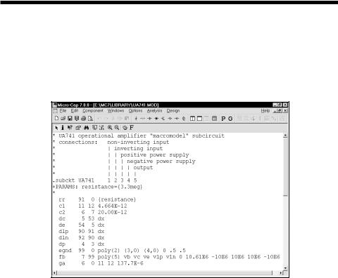
The first step is to create the subcircuit circuit itself. We won't do that here. Instead we'll use an existing subcircuit, supplied with MC7. To load the SPICE file, select the Open item from the File menu. Type "..\library\UA741.MOD". The circuit file looks like this:
Figure 12-1 The UA741.MOD subcircuit
This subcircuit is a standard Boyle-type model for the classic UA741. The circuit file can be created with the MC7 SPICE text editor or by using an external word processor. Frequently, it can be obtained as a text file from a manufacturer of the part. It must be placed in the library directory and the file name entered into the "NOM.LIB" file to be accessible to MC7. The file name is entered by adding a line such as,
.LIB "UA741.MOD"
to the NOM.LIB file. The NOM.LIB file is located in the library folder.
208 Chapter 12: Working with Subcircuits
Selecting a suitable shape for the subcircuit
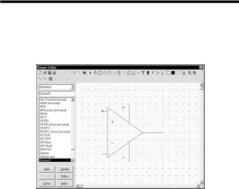
The second step is the selection or creation of a suitable shape. Select the Shape Editor from the Windows menu. For our example, the Opamp5 shape will do nicely. It looks like this:
Figure 12-2 The opamp5 shape
If there are no suitable shapes in the library, you can create a new one to visually suggest the function of the subcircuit. All shapes created are added to and appear in the Shape list field of the Component editor.
209
Putting subcircuits into the Component library
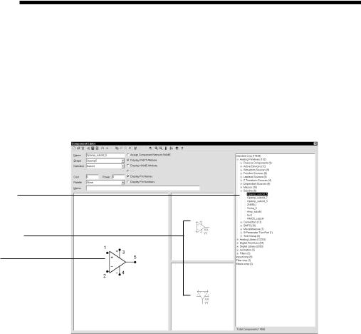
The third step is to enter the subcircuit in the Component library. To do this, select Component Editor from the Windows menu. Double-click on the Subckts group of the Analog Primitives group. This presents a list of the existing subcircuits. Click on the Opamp_subckt_5. This shows the existing Opamp_subckt_5 component. If you were adding this component as a new subcircuit you would have clicked first on the Subckt group to select it, then clicked on the Add Part button to add the Opamp_subckt_5 component to the macro group and edited the data fields to look like these:
Component selector
Attribute placement fields
Shape /pin display
Figure 12-3 The subckt Component library entry
The first data field is the Component name. This can be any alphanumeric name. It does not need to be the name of the subckt. In this case we used the general name, Opamp_subckt_5, but we could also have chosen the name UA741.
The Shape entry is the name of the shape to be used to represent the macro. Here we have selected the Opamp5 shape. Click on the down arrow to see a list of the available shapes from the Shape library.
The Definition field is where you specify the electrical definition. In this case, we specify Subckt. Click on the down arrow to see a list of the available definitions.
210 Chapter 12: Working with Subcircuits
The Attribute placement fields define the location of the attribute text (XX and YY in Figure 12-3) relative to the shape. Subckt attribute text is comprised of the PART attribute which provides the part name, the NAME attribute which specifies the name of the subcircuit, the optional FILE attribute which specifies the name of the file containing the .SUBCKT statement, the PARAMS attribute which provides any passed numeric parameters, and the TEXT attribute which provides any passed text parameters. These attributes are specified when the component is placed in a schematic. The Attribute placement fields let you drag the text with the left mouse button to define where the first (XX) and second (YY) attribute text will be initially placed. After the component is placed, attribute text can be relocated by dragging with the mouse.
An important aspect of entering a subckt into the library is defining where the pins are. For a component like a BJT, the pin names are predefined as Emitter, Base, and Collector. For a subckt, the pin names and locations must be defined by the user. This is done by clicking in the Shape / pin display field. This activates a Pin dialog box, allowing you to enter a new pin name and to specify if it is digital or analog. Double-clicking on an existing pin lets you edit it. Both the pin marker dot and the pin name can be independently dragged with the mouse to the desired locations.
The pin names used in the Component library must match those in the .SUBCKT statement in the file that contains the subckt itself. For example, the UA741 uses "1" as the name of the positive input pin, so we need a pin named "1" at the position on the shape we want to identify as the positive input pin. Similarly, "5" is used as the name of the output pin so we want to have a pin named "5" placed on the shape where we expect to find the opamp output.
UA741 Subckt Pin Names |
Description |
1 |
Positive input pin |
2 |
Negative input pin |
3 |
Positive power pin |
4 |
Negative power pin |
5 |
Output |
Notice that you could put the pins anywhere. There is no magic in placing the positive input pin near the + symbol. It is simply easier to remember where the pins are when you wire them into a circuit.
Close the Component editor.
211
Using the subcircuit as a component
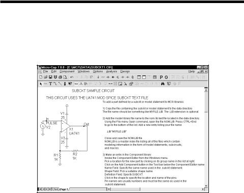
The final step is using the subckt. Once it has been entered into the Component library, it is available for use in any circuit and can be accessed from the Component menu group where it was added. Unload the UA741.MOD SPICE file and load the SUBCKT1 circuit. It looks like this:
Figure 12-4 Using the subckt component
The key points about using a subckt are:
1.When the part is placed in a circuit, its NAME attribute must be the same as its .SUBCKT name.
2.MC7 searches for the subckt in the following places:
•The text area of the schematic. You can paste the subckt to the text area and avoid the need to copy the subckt file to the library directory.
•The file name listed in the File attribute.
•The files in any .LIB statements, including the default .LIB NOM.LIB.
This is the preferred and most common access method.
3.Many different subcircuits can be covered with a single, generic subckt entry in the Component library, if they have the same pins and node order.
212 Chapter 12: Working with Subcircuits

Using the Add Part wizard to add subckt parts
The procedure described in the previous pages describes how to add a subckt part from scratch. Frequently, you may wish to add a part model supplied by a semiconductor parts vendor. The easiest way is to use the Add Part wizard. It combines the three basic steps into one operation.
1)Copy the file containing the subckt or model statement to the library folder.
2)Add the model file name to the nom.lib text file located in the library folder.
3)Make an entry in the Component library.
Suppose you have downloaded a file called AD.LIB from a vendor to the location C:\. In the file is a subckt statement for the power NMOS device IRF5101A. You want to add it to the library. Here is what you do.
1)Select Component Editor from the Windows menu.
2)Select the group where you want the part name to appear in the Component menu. For this illustration simply select Analog Library
3)Click on the Add Part wizard  button.
4)The first prompt is for the part name. Type in "IRF5101A". Click Next.
5)The next prompt is for the electrical definition. Select Subckt. Click Next.
6)The next prompt asks for the name of the file containing the subckt. Type C:\AD.LIB ( or wherever the file currently resides). Click Next.
7)The next prompt is the tricky one. The wizard has scanned the Component library and compiled a list of all subckt based parts that have pin names matching those it found for the IRF5101A subckt. Actually it tries to present only a representative list, as there may be thousands of possible parts. Select one from the list. In this case we will select the DNMOS as we know this to be a discrete NMOS device. Click Next.
8)The next prompt asks for an optional memo field. Click Next.
9)The next prompt asks for an optional palette assignment. Click Next.
213

10)The next panel lets you set the visibility of the various part attributes. Click Next.
11)The next panel lets you make the assignment of the component name to the NAME attribute. This assignment avoids the need to invoke the Attribute dialog box when one of these parts are added to a schematic. Click to enable the option. Click Next.
12)The final panel advises you to examine the entry to be sure all elements have been selected properly, particularly the choice of shape and where the pin names have been placed on the shape.
For our example, the new part should look like this.
Figure 12-5 The subckt Component library entry
It is also possible to import many parts simultaneously from one file. That is done with the Import wizard. Its operation is described in the Reference manual.
214 Chapter 12: Working with Subcircuits