

Micro-Cap v7.1.6 / Ug
.pdfDialog boxes
When you select options or enter data it is frequently done through a dialog box. Here, for example, is the Open dialog box for files:
Figure 2-19 The Open dialog box
Both the mouse and keyboard may be used for selection or data entry. The selected field will be highlighted or framed.
Using the keyboard: The TAB key is used to move among the fields. For text entry fields such as a file name, the data is simply typed in. The SPACEBAR is used to select the Open, Cancel, and Help options. For drop-down boxes or lists, the cursor keys may be used to scroll among the options. Type the first letter of the desired item to rapidly locate the group of items that begin with the letter. In the directories list, the ENTER key and cursor keys are used to change to a new directory. The TAB key moves through the fields in one direction and SHIFT + TAB moves in the opposite direction.
Using the mouse: Move the mouse to the desired field and click. For text entry fields such as a file name, the data is simply typed in. For the Open, Cancel, and Help items, click the buttons to select the option. For drop-down boxes, click on the drop-down arrow, and then click on the desired selection. In the directories menu, double click on the directory icon to change to that directory.
25
The File menu
The File menu provides commands for the management of schematic circuit files, SPICE circuit files, document text circuit files, and model library files.
•New: (CTRL + N) This command invokes the New dialog box to create a new file.
•Open: (CTRL + O) This command invokes the Open dialog box to load an existing file from the disk.
•Save: (CTRL + S) This command saves the active window file to disk using the name and path shown in the title bar.
•Save As: This command saves the active window file to disk after prompting the user for a new file name and (optionally) a new path.
•Paths: This lets you specify one or more default paths for DATA (circuits), LIBRARY (model libraries), and PICTURE (wmf and bmp picture files).
If more than one path is specified, they must be separated by a semicolon (;). MC7 first looks locally in the circuit for model data. It looks in the LIBRARY paths next, searching multiple paths in left to right order.
•Translate:
•Binary Library to SPICE Text File: This command translates a binary MC7 library parameter file, FILE.LBR, into a text file, FILE.LIB, containing model statements.
•SPICE Text File to Binary Library: This command translates a SPICE text file, FILE.LIB, containing model statements, into a binary MC7 library parameter file, FILE.LBR.
•Schematic to SPICE Text File: This command creates a SPICE netlist from the active schematic. Any or all analyses may be specified and several types of SPICE formats may be specified.
•Schematic to Printed Circuit Board: These commands create netlist files to be used as input to the Protel, Accel, OrCad, or PADS.
•MC7 Schematic to MC5 Version 1 Schematic File: This command saves the circuit file to disk under the older MC5 Version 1.0 format
26 Chapter 2: Exploring The Basics

•MC7 Schematic to MC5 Version 2 Schematic File: This command saves the circuit file to disk under the older MC5 Version 2.0 format.
•MC7 Schematic to MC6 Schematic File: This command saves the circuit file to disk in the MC6 format, creating a file that MC6 can read.
•Bill of Materials: This command creates a bill of materials for the schematic listing part name, type, value, quantity, cost, and power budget.
•Load MC File: This command loads a circuit numeric output file and scans it for references to Monte Carlo performance function error reports. It then creates the circuits which caused errors during the Monte Carlo run, showing each circuit with parameter values which caused failure. Failure means not meeting a performance function limit (like rise time or delay) specified in the original Monte Carlo run.
•Revert: This command restores the file in the active window to the one currently on disk.
•Close: (CTRL+F4) This command closes the active file. This means it removes it from the MC7 memory but not from the disk. It will optionally ask if you want to save any changes on disk.
•Print Preview: This option previews what the printed schematic, analysis plot, 3D plot, performance plot, or Monte Carlo plot will look like with current print options. It also lets you select, move, and re-size the schematic and plot.
•Print: (CTRL+P) This command prints a copy of the document shown in Print Preview in accordance with the instructions in Print Setup.
•Print Setup: This option changes the printer settings and paper choices. Its format will vary with different printers, but usually it lets you specify a particular printer to use and the paper size, source, and orientation.
•Recent Files: This is a list of the most recently used files. You can reload or display any one of them by clicking on its file name. The number of files displayed is set by the File List value in the Common Options section of the Preferences dialog box.
•Exit: (ALT+F4) This exits Micro-Cap 7.
27
The Edit menu
This menu provides the following options. Equivalent tool bar buttons appear next to the commands below.
•Undo: (CTRL + Z) MC7 has a multistage undo. It can undo the last N operations that change a circuit file. N is limited only by RAM memory and is usually greater than 20. Undo can also restore the last state of a text field, if the text cursor is still in the field.
•Redo: (CTRL + Y) Redo operates in the opposite direction of Undo. It restores the prior circuit state. Like Undo, it can redo the last N operations that change a circuit file.
•Cut: (CTRL + X) This command deletes the selected objects and copies them to the clipboard. Objects include text field text and schematic objects.
•Copy: (CTRL + C) This command copies selected objects to the clipboard. Objects include text from text fields and schematic objects.
•Paste: (CTRL + V) This command copies the contents of the clipboard
to the current cursor position. If a group of characters in a text field is currently selected at the time of the Paste operation, they are replaced with the text in the clipboard. If the front window is a schematic, the paste is done from the last point in the schematic where the mouse was clicked.
•Clear: (DELETE) This command deletes the selected items without copying them to the clipboard. This command deletes selected wires from their end points.
•Clear Cut Wire: (CTRL + DELETE) This command deletes selected wires by cutting them exactly at the sides of the select box.
•Select All: (CTRL + A) This command selects all objects in the current window or all text in the current text field or document.
•Copy to Clipboard: This command copies all or part of the visible portion of the front window in graphics format to the clipboard. It copies all or a part of the window contents in BMP, WMF, or EMF format to the clipboard. The picture in the clipboard may then be imported via pasting to other programs, such as Word, Excel, or MC7.
28 Chapter 2: Exploring The Basics

You can't paste a clipboard picture to MC7, though you can import a picture file to MC7 using the Picture item from the Mode part of the Options menu. After selecting the Picture mode, drag or click in the schematic and MC7 prompts for the picture file name.
•Copy the Entire Window to a Picture File: This command creates a picture file in BMP, WMF, or EMF format from the front window. The file can then be imported into MC7 or other Windows applications.
•Add Page: This command adds a new page to the schematic.
•Delete Page: This command deletes one or more schematic pages.
•Refresh Models: This command localizes circuit model information by copying subckts and model statements from the libraries to the circuit. It is a handy way to embed model information in the file prior to sending a copy of the circuit to a colleague who may not have your models. It can also serve as a refresh step, restoring model information from the master libraries in case you have edited the models and want to restore them.
•Box: These commands affect objects enclosed in the selected region.
•Step Box: This command steps all objects within the selected region vertically, horizontally (or both) a specified number of times.
•Mirror Box: This command creates a horizontal or vertical mirror image of the objects enclosed in a selected region.
•Rotate: (CTRL + R) This command performs a counterclockwise rotation of the objects in a selected region.
•Flip X: This command flips the objects in a selected region about the X-axis. The X-axis is defined as the horizontal line that bisects the selected region.
•Flip Y: This command flips the objects in a selected region about a Y- axis. The Y-axis is the vertical line that bisects the selected region.
•Make Macro: (CTRL + M) This command makes a macro circuit from the circuitry inside of the current box region. It gathers the circuitry into a new circuit, labels the pin names, saves the circuit to disk under a name you choose, records an entry in the Macro section of the
29

Component library, and replaces the circuitry within the box region with an adjustable macro symbol representing the circuitry. After the macro command, the circuit will simulate just as before, but the schematic will have less clutter.
•Change: This option lets you change several attribute features:
•Properties: (F10) This accesses the Characteristics dialog box for the circuit window. From here you can change the color of circuit features such as wire or component color. Changes affect all objects rather than just selected objects.
Attributes: This lets you change the display status of the five main attributes of all components in the circuit, en masse.
Color: This lets you change the attribute color of selected components.
Font: This lets you change the attribute font of selected components.
Rename Components: This command renames all components using standard naming conventions. It also reorders the components to make the node numbers flow from left to right and top to bottom. It updates the component names in analysis plot expressions, so that R(RRX) changes to R(R5) if the part name is changed from RRX to R5. It does not update node numbers in analysis plot expressions, however, so expressions like V(10) will not be changed to V(2) if node 10 gets changed to node 2.
Rename Defines: This command renames all .defined symbolic names where conflicts exist between the symbol name and predefined names.
Reset Node Positions: The relative printing position of the node number, node voltage, current, power, and condition can be changed by dragging its text. This command provides a way to restore their original default positions.
• Bring to Front: A mouse click on a stack of overlapping objects selects the front object in the stack. If the front object isn't the one you want, a way is needed to select other objects from the stack. This command makes the selected object the front object.
• Send to Back: This command makes the selected object the back object.
30 Chapter 2: Exploring The Basics

•Go To Flag: This command invokes the Go To Flag dialog box. It lets you reposition the display on a flag. Select a flag and click on the OK button and the program redraws the schematic, with the selected flag at the center of the display. This item is enabled only when there are flags in the schematic.
•Find: (CTRL + F) This command invokes the Find dialog box, which is used to search the circuit window for a variety of objects, including part names, node names, attributes text, component type, and grid text.
•Repeat Last Find: (F3) This command repeats the search and finds the next object in the circuit that matches the search criteria.
•Replace: This option replaces text in a text document or in the text area of a schematic. The replace function for schematic attributes is done from the Attribute dialog box using the Change button.
31
The Component menu
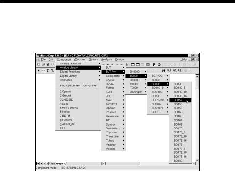
This hierarchical menu shows the contents of the Component library. The library was created and can be edited by the Component editor, although most users will not need to do much editing. One part of the menu looks like this:
Figure 2-20 The Component menu
The menu selects a component for adding to the schematic. The first level of the menu is divided into several sections.
Analog Primitives: The Analog Primitives section contains generic analog components for which the user supplies the values or model statements that define their electrical behavior.
Analog Library: The Analog Library section contains models for commercially available analog components. The values or model statements that define their electrical behavior are provided in the Model library.
Digital Primitives: The Digital Primitives section contains generic digital components for which the user supplies the values or model statements that define their electrical behavior.
Digital Library: The Digital Library section contains models for commercially available digital components. The values or model statements that define their electrical behavior are provided in the Model library.
32 Chapter 2: Exploring The Basics
Animation: This section contains objects which change their display or respond to user clicks during a simulation. The objects include a seven-segment display, an LED, and a switch which toggles its state between 1 and 0 when you click on it. These objects are designed to operate in transient or DC analysis in conjunction with the Animate mode. In this mode, a single analysis step (time or DC voltage or DC current) is taken and the states and animate devices are updated on the schematic. MC7 then waits for either a key press or a specified time delay before taking the next time step. The purpose is to slow the simulation down to show individual node voltage or state changes.
Filters: This section holds filter macros created by the filter design function (accessed from the Design menu). It is absent until one or more filter macros are created.
Find Component: (CTRL + SHIFT + F) This command lets you search the Component library for a part. Because there are thousands of parts in the library, you may need to search for a part without knowing its full name. This command lets you specify a name or a part of the name. It then displays a list of the parts whose names or, other fields, match the characters you have typed in. You then click on the name of the part you want and the OK button and MC7 sets the default part to the one you selected, a click away from adding it to the schematic.
You can search the Name, Shape, Definition, Memo, or All fields and you can specify whether the text must match at the beginning of the field or not.
For example, to search for any parts that use the word filter in their Memo field, select the Memo option and disable the Beginning of Line option. The search shows several switched-capacitor and several linear filters.
To select a component for placement click the mouse on one of the menu items and click on the OK button. When you select a component, MC7 automatically changes the tool mode to Component.
To actually place the component, click the left mouse button in the schematic, or click and drag the component to where you want it to be placed. To rotate the component, click the right button before the left button is released.
33
The Windows menu
•Cascade: (SHIFT + F5) This command cascades the open circuit windows in an overlapping manner.
•Tile Vertical: (SHIFT + F4) This command vertically tiles the open circuit windows in a non-overlapping manner.
•Tile Horizontal: This command horizontally tiles the open circuit windows in a non-overlapping manner.
•Overlap: This command overlaps the circuit window and the analysis plot window. If the Plot on Top option is enabled, the circuit is maximized and
a 1/4 size analysis plot is placed on top, otherwise the plot is maximized and a 1/4 size circuit is placed on top. This option is available only when a normal or Probe-mode transient, AC, or DC analysis is active.
•Maximize: This command maximizes a selected circuit window or circuit window icon.
•Arrange Icons: This command neatly arranges any minimized circuit window icons.
•Zoom-In: (CTRL + numeric keypad + ) If the active circuit window is a schematic, this command magnifies the schematic. This command affects only the display, not the printed size. If the active circuit window is a text window, this command draws the window using the next largest font size.
•Zoom-Out: (CTRL + numeric keypad - ) If the active circuit window is a schematic, this command shrinks it. The command affects only the display, not the printed size. If the active circuit window is a text window, this command redraws the window using the next smallest font size.
•Toggle Drawing/Text: (CTRL + G) Every schematic has a drawing area and a text area. The drawing area contains the schematic. The text area stores modeling information, such as model statements, digital stimulus command statements, and source table statements. This command toggles the window display between the drawing and text areas.
•Split Horizontal: This command horizontally splits the front schematic window into its drawing and text areas for simultaneous viewing.
34 Chapter 2: Exploring The Basics