

Micro-Cap v7.1.6 / Ug
.pdfThe Shape editor
The Shape editor is used to create and maintain the shapes, or graphical images used to represent the component in a schematic. It looks like this:
Tool bar
Shape list
Drawing region
Figure 2-23 The Shape editor
Shapes are created by selecting drawing tools from the Tool bar and clicking or dragging the mouse in the Drawing region to create a graphical object.
The Scale buttons in the Tool bar change the display size of the shape image shown in the Drawing region.
The Add button adds a new shape. The Delete button deletes the currently selected shape. The Object editor button invokes an editor that lets you edit the specific numerical values that determine a particular object's size or other features.
The Tool bar provides many specific tools and objects which are described in more detail in the Reference Manual.
55
The Model editor
Model libraries provided with MC7 come in two forms, text and binary.
In text form they are contained in files with the extension LIB, and encode device models as .MODEL, .MACRO, and .SUBCKT statements. Text files can be viewed and edited with any text editor, including the MC7 text editor.
In binary form, model libraries are contained in files with the extension LBR, and are implemented as a list of model parameters for the parts. These binary files can be viewed and edited only with the Model editor. The Model editor is invoked when the File menu is used to open or create a binary library file.
The Model editor should not be confused with the MODEL program, which is accessed from the Windows menu. MODEL is a separate Windows program which produces optimized analog model parameters from commercial data sheets. MODEL can create model libraries in either the text or binary form.
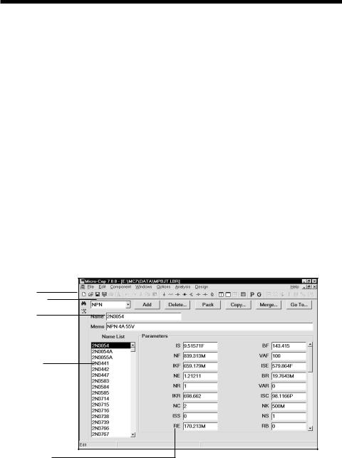
Once binary libraries are created, the Model editor can view and edit them. The Model editor display looks like this:
Menu bar
Type selector
Part name
Part selector
Model display
Figure 2-24 The Model editor
56 Chapter 2: Exploring The Basics
The various parts of the editor function as follows:
•Name: This field is where the part name is entered. If the part has been imported from the MODEL program, this field is a copy of the T1 text field.
•Memo: This is a simple text field that may be used for any descriptive purpose. If the part has been imported from the MODEL program, this field is a copy of the T3 text field.
•Type selector: This is used to select which device type to display. Each library may contain a mixture of different device types. Selecting NPN for example, displays all of the NPN bipolar transistors in the file.
•Part selector: This selects a part by name for display and possible editing. It provides a window to review the specific model values for the displayed part. As in other windows, the Maximize button may be used to enlarge the window to see more of the model values.
•Add: This adds a new part of the current device type to the current library.
•Delete: This deletes the displayed part.
•Pack: This removes all duplicated and untitled parts and reorders the parts alphanumerically.
•Copy: This command copies a part from the displayed library to a target library. If the target library already has a part with the same name, the name of the newly created copy is set to "name_copy". The target library may be the current library.
•Merge: This command merges a library from disk with the displayed library. The merged library is displayed but not saved to disk.
•Go To: This command lets you specify a parameter name, then scrolls the parameter list of the currently displayed part to show the parameter value.
Note that the Find function is available to locate parts by name in the current library file or in one of the library files on disk. Simply click on the Find
button  in the Tool bar.
57

Function keys
F1 is used to invoke the Help system. It accesses an information data base by contents and by alphabetical index.
F2 is used to start an analysis after selecting the type of analysis from the Analysis menu.
F3 quits the AC, DC, or transient analysis and returns to the Schematic editor. F3 also repeats the last search when in the Schematic editor.
F4 displays the analysis plot.
CTRL + F4 closes the active window.
F5 displays the Numeric Output window.
F6 scales and plots the selected analysis plot group.
CTRL + F6 cycles through the open windows.
F7 switches the analysis plot to Scale mode.
F8 switches the analysis plot to Cursor mode.
F9 displays the Analysis Limits dialog box for AC, DC, or transient analysis or their Probe equivalents.
CTRL + F9 clears the waveforms in Probe and invokes the Analysis Limits dialog box when in an analysis module.
F10 invokes a dialog box for the front window that lets you change the front window characteristics. The type of dialog box depends upon the type of front window.
F11 invokes the Parameter Stepping dialog box.
CTRL + F11 invokes the Optimizer dialog box.
F12 invokes the State Variables editor.
58 Chapter 2: Exploring The Basics

The Undo and Redo functions
Micro-Cap 7 has a multistep undo and redo capability. All schematic edits can be undone back to the point where the circuit was loaded. In general, text field undo is limited to the last state. The one exception to this is the Component editor, where text field edits are multistep.
Undo is accomplished by clicking on the Undo button  or by pressing CTRL + Z. The Undo function is shown under the Edit menu.
Redo is accomplished by clicking on the Redo button  or by pressing CTRL + Y. The Redo function is shown under the Edit menu.
For instance, suppose you load a circuit, and add a diode to it, then change a resistor value from 1K to 2K, then delete a capacitor. Pressing Undo once restores the capacitor. Pressing Undo again restores the resistor value to 1K. Pressing Undo again removes the diode, restoring the schematic to its initial state. Pressing Redo once restores the diode. Pressing it again restores the resistor to 2K, and a third press deletes the capacitor. Only RAM memory limits the depth of the undo/ redo for schematics.
Schematic edits may be undone even after running an analysis. You can delete a region of circuitry from a circuit, run an analysis, then return to the Schematic editor and use the Undo function to restore the circuit to its former condition.
Note that the Revert command on the File menu also functions like a large-scale undo command. It loads the existing version of the front window file from disk, discarding any changes to the front window that occurred since it was loaded.
59
60 Chapter 2: Exploring The Basics

Chapter 3 Creating and Editing Simple Circuits
What's in this chapter
This chapter shows you how to create and edit simple circuits. The goal of this chapter is to introduce the basic techniques and to refine them into working skills by practicing on sample circuits. The particular subjects covered are:
•Schematic creation
•Adding components
•Entering component parameters
•Connecting components with wires
•Using define and model statements
•Adding node names
•Schematic editing
•Text editing modes
•Editing component parameters and text
•
•
•
Deleting objects
The clipboard
Selection
•Viewing large schematics
•Creating and editing SPICE text files
61
Creating a simple circuit
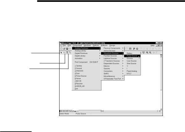
Begin by double-clicking the mouse on the MC7 icon. The program automatically opens a circuit window and names it CIRCUIT1. Using the mouse, select the
Component menu, then Analog Primitives, then Waveform Sources, and finally, select Pulse Source.
Select mode button
Component mode button
Text mode button
Selecting a part from the menu changes the mode to Component,anticipating the placement of the component in the schematic.
Figure 3-1 Selecting a part from the Component menu
The cursor changes to a pulse source shape. Click the left mouse button and hold it down. Press the right mouse button and the shape rotates. Eight clicks of the right mouse button produce the eight possible orientations. While still holding the mouse button down, slide the source to a position halfway down the circuit window and near the left window edge. Rotate it until the plus symbol is on top and the minus symbol is on the bottom. Release the mouse button. This activates the Attribute dialog box as shown in Figure 3-2.
For this type of source there are two important attributes, the part name and the model name. MC7 creates a suitable part name, in this case V1, which you can accept or edit. For some parts from the Analog Primitives section, we must also specify a model name. You can type in a new model name or select a model from the Model list box. Select the SAWTOOTH model from the list box.
If you enter a name that is not in the Model library, MC7 loads a set of default parameters. If you pick a part from the Model list, MC7 reads the model parameters from the library source file. Either way the parameters are displayed for
62 Chapter 3: Creating and Editing Simple Circuits

Attribute value field
Plot selector
Attribute list box
Model list box
Figure 3-2 The Attribute dialog box
review and editing. The model parameters shown are global, as you can see by the line: Source: Global library located at E:\MC7\LIBRARY\UTILITY.LBR
Place the cursor in the VZERO field and change it from 0 to 1. Click in any other field and the model parameters become local to the circuit as you can see in the line: Source: Local text area of E:\MC7\DATA\CIRCUIT1.CIR
This illustrates a principal point of how MC7 stores and accesses model data such as subcircuit descriptions and model parameters:
Model data is global until edited when it becomes local to the circuit.
Global means the information is stored in the MC7 library folders. Each time you run an analysis, MC7 uses the global libraries to build the simulation data base.
Local means the information is stored within the circuit. Each time you run an analysis, MC7 uses the local in-circuit copy of the models to build the simulation data base.
To localize or simply refresh model information, use the Refresh  command. This command can either copy model data into the local circuit or refresh model data already there depending upon the options chosen from its dialog box.
.
63
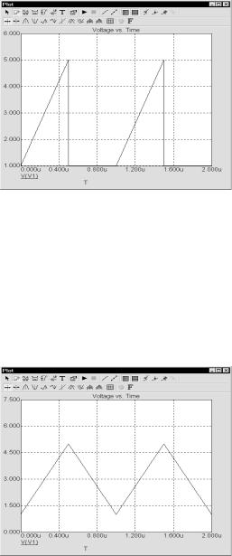
You can see the pulse source waveform by clicking on the Plot button. For this set of parameters the waveform looks like this:
Figure 3-3 Characteristic plot of the source
The Plot button produces zero to three plots for each basic part type (primitive). The plots are created on the fly from mini-simulations of test circuits designed to produce the plot in question. Some parts, like the Pulse source, have a simple simulation and a single plot. Others, like the NPN, have several plots that can be chosen from the plot selector. Some parts, like macros and subckts, have no plot at all since it is impossible to know what would be a relevant plot for a general part like a subckt. Once the plot is up, it responds dynamically to parameter edits. To illustrate, change the value of P4 to 1U and the plot looks like this:
Figure 3-4 Characteristic plot of the source with P4=1u
Click OK to place the edited SAWTOOTH pulse source.
64 Chapter 3: Creating and Editing Simple Circuits