

Micro-Cap v7.1.6 / Ug
.pdfFigure 9-3 Stepping BF in a single transistor
Now we'll use CJE to illustrate log stepping. Press F11 to access the Stepping dialog box. Click on the Model button and the Log button. From the left list box select NPN N1, and from the right list box, select CJE. Type "2P" into the From field, "16P" into the To field, and "2" into the Step Value field. Click OK. Press F2 to start the run and it looks like this:
Figure 9-4 Log stepping CJE
175
AC and DC examples
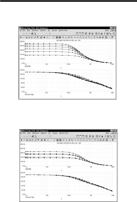
Press F3. Select Revert from the File menu. Press ALT + 2 to select AC. Press F11, click the Yes button in the Step It group. Press ENTER. Press F2.
Figure 9-5 AC analysis linear stepping
To illustrate list stepping, press F11. Click the List option in the Method group. Type "100,110,150,160,200,210" in the From field. Press ENTER, then F2. The run looks like this:
Figure 9-6 AC analysis list stepping
176 Chapter 9: Stepping Component Parameters

To illustrate stepping in DC, press F3 to exit the analysis. Press ALT + 3 for DC analysis. Press F11, click on the Linear option, Click on the Yes button, click OK, then press F2 to start the DC run. It looks like this:
Figure 9-7 DC analysis linear stepping
To illustrate multiple parameter stepping, press F11, click in the Yes option in the Step It field of parameter 2. Press ENTER, then F2. The run looks like this:
Figure 9-8 DC analysis stepping
Here we've simultaneously stepped BF and NF of all transistors using the N1 NPN model. Nested stepping was selected, and each parameter has six values, so 6•6 = 36 runs were done.
177
Text stepping
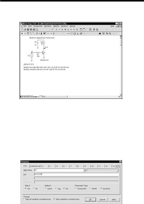
Text can also be stepped. Consider the circuit below:
Figure 9-10 Stepping the N1 variable
Here Q1's model is set to N1, which is defined as N1A via the statement,
.DEFINE N1 N1A
If we step N1 through a list that includes N1A and N1B, we get two simulations. One is for the case when N1 is N1A and uses the N1A model parameter set. The second is for the case when N1 is N1B and uses the N1B model parameter set.
The Stepping dialog box for this case is shown below.
Figure 9-11 The Stepping dialog box for text stepping the N1 variable
178 Chapter 9: Stepping Component Parameters
Notice two things about text stepping:
1)Text stepping is done with a symbolic variable that is created and defined with a .DEFINE statement.
2)Text stepping is done with the List method.
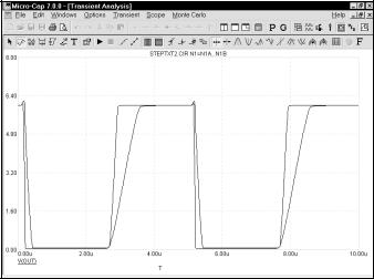
Here is what the simulation looks like for the specified stepping.
Figure 9-12 The simulation run
The two runs use two different model parameter sets and produce two different output curves.
179

Stepping summary
The most important things to remember when using stepping include:
1.The parameters of these components may not be stepped:
•Transformer
•User sources
•Laplace sources
•Function sources
•SPICE dependent sources (E,F,G,H sources)
•MC4 Switches; the S and W switches can be stepped.
The behavior of User, Laplace, Function, and SPICE sources is embodied in algebraic formulas and numeric tables, and thus can't be stepped. You can, however, step symbolic parameters which in turn are used in Laplace, Function, and SPICE source functions. For example, you could use,
.DEFINE TAU 5
A Laplace function source like,
1/(1+TAU*S)
could then be changed by stepping TAU.
Similarly in a Laplace table source like,
.DEFINE RVAL 2.0
.DEFINE TAB (1k,0,RVAL)
you could change the behavior of the source by stepping RVAL.
The User source gets its data from an external data file and has no parameter that can be stepped.
2. In Component mode, stepping affects one parameter of one device only if the PRIVATEANALOG and PRIVATEDIGITAL options (Global Settings) are enabled. In Model mode, stepping affects one parameter of all devices that use that model name. Thus you are potentially affecting many devices.
180 Chapter 9: Stepping Component Parameters
This is true regardless of the state of the PRIVATEANALOG or PRIVATEDIGITAL flags.
3.Certain model parameters may not be stepped. These include:
•The MOSFET Level model parameter may be stepped, but an error will occur if the model statement has been created with parameters for level 1, 2, or 3 and the level changes to a BSIM model (Level 4, 5, or 8). Each BSIM model uses model parameter names that are different from the other BSIM models as well as the level 1, 2, and 3 models, so the parameter names would be meaningless.
4.Linear stepping starts with the From value and adds the Step Value until it reaches the To value. Log stepping starts with the From value and then multiplies by the Step Value until it reaches the To value. A Step Value of 2 is often convenient and is called octave stepping. A Step Value of 10 is sometimes referred to as decade stepping. List stepping simply uses the values specified in the From field.
5.If multiple parameters are to be simultaneously stepped, they must each specify the same number of steps. If there is a mismatch, an error message is generated.
6.At least two parameters must be varied to create 3D performance plots.
7.Stepping a resistor, capacitor, or inductor that uses an expression for its value, replaces the value calculated from the expression with the step value. In other words, the step value takes precedence over the calculated value.
8.Text stepping requires a variable created with a .DEFINE statement and the List method must be used.
181
182 Chapter 9: Stepping Component Parameters

Chapter 10 Using Monte Carlo
What's in this chapter
Monte Carlo analysis statistically tests circuit performance. It creates a batch of circuits populated with toleranced components. After the analysis of each circuit, it employs user-selected functions to extract performance data from curves plotted or printed during the run. The results are statistically analyzed and plotted in the form of histograms. Careful review of the data can yield valuable insights into the reliability, cost, and the ability to manufacture the circuit.
Monte Carlo statistical analysis is available in transient, AC, and DC analysis.
Stepping and Monte Carlo are mutually exclusive. Either one, but not both, may be run simultaneously.
The chapter is organized as follows:
•How Monte Carlo works
•Distributions
•Performance functions
•Options
•An example
•Statistical summary
183

How Monte Carlo works
Monte Carlo works by analyzing many circuits. Each circuit is constructed of components randomly selected from populations matching the user-specified tolerances and distribution type.
Tolerances are applied to a component's numeric model parameters. Only model parameters and symbolic parameters can be toleranced. Tolerances are specified as an actual value or as a percentage of the nominal parameter value.
Both absolute (LOT) and relative (DEV) tolerances can be specified. A LOT tolerance is applied absolutely to each device. A DEV tolerance is then applied to the first through last device relative to the LOT toleranced value originally chosen for the first device. In other words, the first device in the schematic list receives a LOT tolerance, if any. All devices, including the first, then receive the first device's value plus or minus the DEV tolerance. DEV tolerances provide a means for having some devices track in their critical parameter values.
Both tolerances are specified by including the key words LOT or DEV after the model parameter:
[LOT[t&d]=<value>[%]] [DEV[t&d]=<value>[%]]
For example, this model statement specifies a 10% absolute tolerance to the forward beta of the transistor N1:
.MODEL N1 NPN (BF=300 LOT=10%)
In this example, for a worst case distribution, each transistor using the N1 model statement has a forward beta of either 270 or 330. If a Gaussian distribution were used, a random value would be selected from a Gaussian distribution having a standard deviation of 30. If a uniform distribution were used, a random value would be selected from a uniform distribution having a half-width of 30.
This example specifies a 1% relative tolerance to the BF of the N1 model:
N1 NPN (BF=300 DEV=1%)
The DEV value specifies the relative percentage variation of a parameter. A relative tolerance of 0% implies perfect tracking. A 1.0% DEV tolerance implies that the BF of each N1 device is the same to within 1.0%. Model statements that use
184 Chapter 10: Using Monte Carlo