

Interfaces
Interfaces
Purpose Interfaces are used to exchange data with ported peripheral devices:
Measured values and calculated values can be output to a printer, PC or control display; conversely, control commands and data inputs can be sent to ported devices (PC, keyboard, foot switch, barcode scanner).
Except for PS2, each interface has to be configured according to the peripheral device and desired function. No error messages are generated just because no device is connected to an interface port (open data port).
Features |
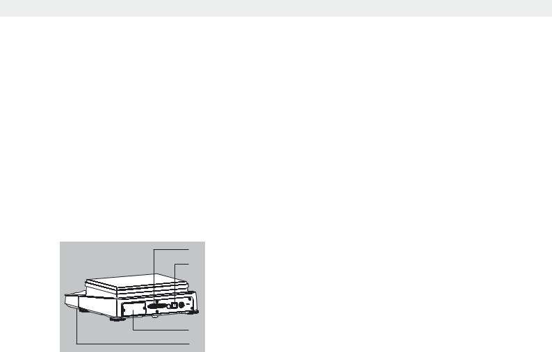
Cubis series balances have at least three interfaces: |
|
1 |
1 |
Peripheral port (25-pin interface), Com A |
2 |
2 |
USB interface for a PC connection, Com B |
3 |
The slot may contain other ports (Com C): |
|
|
– |
25-pin interface (YDO01MS-R) |
|
– 9-pin interface with 6-pin PS2 port (YDO01MS-P) |
|
|
– |
Bluetooth® module (YDO01MS-B) |
4 Ethernet interface (on the bottom of the display unit), Com D
3
4
Data Exchange Protocols For data exchange, the interfaces are configured with the following protocols:
–Printer output
–SBI (Sartorius Balance Interface): Sartorius standard protocol for output to a PC or control unit. This simple ASCII-based protocol allows you to use ESC commands from your PC to control the basic weighing functions.
–xBPI (eXtended Balance Processor Interface, also called X-Bus): Binary protocol with extended command volume. This protocol lets you control numerous weighing functions. For further information on this, please contact Sartorius.
–SICS and mini-SICS (Standard Interface Common Set): This interface protocol enables operation and control of the balance via a connected PC. You can read out measurement data, enter weighing commands and activate all operating
functions.
To use the protocols, application software must be installed on the PC, e.g., SartoTerminal.
Synchronization During data communication between balance and PC, messages consisting of ASCII or binary characters are transmitted via the interface. For error-free data exchange, parameters for baud rate, parity, handshake mode and character format must be identical for both units.
You can configure the respective settings in the System Settings menu. In addition to these settings, data output for the balance can also be made dependent on several conditions that are defined in the individual tasks. These conditions are described under each of the tasks.
Cubis MSA User Manual |
135 |
|
|

Interfaces
USB Port (PC)
Purpose Any Cubis balance can be connected to a PC equipped with a USB port. A virtual serial interface (virtual COM port) is set up as a device type at the USB port. This virtual serial interface is identified und operated by the application program.
The protocols xBPI, SBI and SICS can be transferred via the USB port.
3The USB port is designed for the laboratory environment and is not suitable for use in purely industrial environments. Full IP protection is only guaranteed when the USB cover is closed.
System Requirements – Computer (PC) with Windows 98SE®, Windows ME®, Windows 2000®, Windows XP®, Windows Vista® or Windows 7®
–Available USB port on the PC
–USB cable
Software Driver and Installation Guides The VCP driver, used to set up the virtual interface on the computer, can be downloaded from the internet: http://www.ftdichip.com/FTDrivers.htm
The installation guides for the drivers can be found here:
http://www.ftdichip.com/Documents/InstallGuides.htm
Connecting the Balance via USB
hThe current USB port for the computer is established when the software driver is being installed. The driver must be re-installed every time you wish to change the port. Therefore, choose one USB port that can permanently or regularly be used to connect the balance.
tSwitch off the balance.
tUnplug the balance from the mains.
tConnect the USB cable to the balance and to the USB port on the computer.
tPlug the balance into the mains again and switch it on.
yWindows detects the device connected to the USB port. If the device is being connected for the first time, the Windows Installation Wizard will run.
Installing Software Drivers
tRun the Installation Wizard for the driver.
tFollow the instructions that appear.
tTo complete the installation, click on Finish.
y The virtual interface is now ready for operation.
Windows® usually adds the virtual port in the position following your highestnumbered COM port.
Example: For a PC with up to 4 COM ports, the new virtual port would then be COM5 (see Device Manager).
Installation Guides for Windows XP®, Windows Vista® and Windows 7®
Changing the Port No. If you use the USB interface with a program that limits the number of COM port designations (e.g., only COM1, 2, 3, 4), you may have to assign one of these port numbers to the new virtual port.
136 Cubis MSA User Manual

Interfaces
t Open the setting for the USB serial port in the Windows® system control panel:
|
– START > My Computer > Control Panel |
|
– System > Hardware > Device Manager |
|
t Open the Connections submenu. |
|
t Double-click on USB Serial Port. |
|
t Select Port Settings / Advanced. |
Change Latency Time |
t Open the settings for the USB serial port, following the above instructions. |
|
t For a faster rate of communication, change the setting for the Latency Timer |
|
to 1 msec. |
Plug & Play Mode in Autoprint (SBI) |
t Open the settings for the USB serial port, following the above instructions. |
|
t Stop the Plug & Play mode from running. |
|
Uninstalling the Driver |
|
The software driver for the USB connection can be uninstalled with the Windows® |
|
Uninstaller. |
|
|
|
|
|
|
|
|
|
|
|
|
PS2 Interface for Barcode Scanner or Keyboard |
|
|
|
|
|
|
|
|
|
|
|
|
Via the PS2 port you can connect a bar code scanner or a PC “QWERTY” keyboard |
|
|
|
|
|
|
|
|
|
|
|
|
to enter data and operate the balance. |
|
|
|
|
|
|
|
Installation |
The interface installation is described in the installation instructions supplied. |
||||
|
|
Connecting the Device |
t Plug the connector plug into the PS2 port on the balance. |
|||||||||
|
|
|
|
|
|
|
|
|
|
|
|
y The input device is operational, no further settings are required. |
|
|
Using the Input Device |
You can input entries directly via the keyboard or bar code scanner whenever an |
|||||||||
|
|
|
|
|
|
|
|
|
|
|
|
input field is open in the display of the balance. |
|
|
|
|
|
|
|
|
|
|
|
|
Key Assignment of the PC Keyboard |
|
|
|
|
|
|
|
|
|
|
|
|
The five context-dependent buttons located at the bottom edge of the display are |
F1 |
F2 |
F3 |
|
F4 |
|
|
F5 |
operated via the function keys F1 to F5 on the PC keyboard. |
||||
|
|
|
|
|||||||||
|
|
|
|
|
|
|
|
|
|
|
|
Whenever the last button on the right is assigned with the function Back, |
|
|
|
|
|
|
|
|
|
Esc |
this function can also be activated using the Esc key on the keyboard. |
||
|
|
|
|
|
|
|
|
|
|
|||
|
|
|
|
D F9 |
The TASK key is operated via F9 (Open Task menu). |
|||||||
|
|
|
|
H F10 |
The USER key is operated via F10 (Open User menu). |
|||||||
|
|
|
|
|
|
p |
|
|
The PRINT key is operated via the Print key of the keyboard. |
|||
|
|
|
|
|
|
|
|
Shift F1 |
Use the shift F1 to select the first entry of a menu. |
|||
|
|
|
|
|
|
|
|
Shift F2 |
Use shift F2 to select the second entry of a menu. |
|||
|
|
|
|
|
|
|
|
|
|
|
|
etc. |
|
|
|
|
|
|
|
|
|
|
|
|
Pin Assignment PS2 |
|
|
|
|
|
|
|
|
|
|
|
|
Pin 1: Keyboard_DATA (universal) |
|
|
|
6 |
|
|
|
|
|
|
|
5 |
Pin 2: Not assigned (larger) |
|
|
|
|
|
|
|
|
|
|
Pin 3: Internal ground (GND) |
||
|
|
|
4 |
|
|
|
|
|
|
3 |
||
|
|
|
|
|
|
|
|
|||||
|
|
|
2 |
|
|
|
|
|
1 |
Pin 4: +5 V |
||
|
|
|
|
|
|
|
|
|||||
Pin 5: Keyboard_CLK (Set)
Pin 6: Not assigned (smaller)
Cubis MSA User Manual |
137 |
|
|

Interfaces
Interfaces (RS-232) 25-pin and 9-pin
1 |
13 |
14 


 25
25
1


 5 6
5 6 


 9
9
The balance is standard-equipped with a 25-pin interface (peripheral port) where different Sartorius peripherial devices can be connected, e.g., hand or foot switch. This interface is also used for the control lines for the Checkweighing application.
A 9-pin interface can be optionally installed. This port is intended for connecting a PC.
3RS-232 cables purchased from other manufacturers often have incorrect pin assignments for use with Sartorius devices. Failure to do so may damage or destroy your weighing system and/or peripheral devices!
t Be sure to check the pin assignments before you connect cables purchased
from other manufacturers.
t Disconnect any lines assigned differently (e.g., Pin 6).Warning when Using Pre-wired RS-232 Connecting Cables for the 25-pin Interface:
Features (*= Factory settings) |
|
|
Type of interface: |
|
Serial Interface |
Interface operating mode: |
|
Full duplex |
|
|
|
Level: |
|
RS-232 |
|
|
|
Interface connector: |
|
D-SUB female connector, 25or 9-pin |
Transmission rate: |
|
600, 1200, 2400, 4800, *9600 and |
|
|
19200 baud (selectable) |
Parity: |
|
*Even, odd, none; blank spaces (selectable) |
|
|
|
Character transmission: |
|
Start bit, 7/*8 bit ASCII, parity, *1 or 2 stop bits |
|
|
(selectable) |
|
|
|
Handshake (selectable): |
25-pin |
For 2-wire interface: Software (XON/XOFF) |
|
|
for 4-wire interface: *Hardware (CTS/DTR) |
|
|
|
|
9-pin |
Hardware (CTS/RTS) |
Operating mode: |
|
*SBI, xBPI, printer, SICS, 2nd display |
Manual print mode |
|
Without stability, *after stability |
|
|
|
Auto print mode |
|
*Without stability, at stability, after load change |
|
|
|
Cancel automatic printing: |
|
Not possible |
Time-dependent automatic |
|
|
printout: |
|
After 1 display update |
Data output of balance: |
|
16 or *22 characters |
|
|
|
Tare after individual printout: |
Off |
|
|
|
|
Basic values, application: |
|
Off |
|
|
|
Connectable Peripherials The following devices can be ported to the interface:
–Verifiable data printer YDP03-0CE, YDP10-0CE, YDP20-0CE
–Verifiable data printer with Bluetooth data transmission YDP10BT-0CE (module required)
–Universal (serial printer)
–Strip/label printer YDP04IS-OCEUV
–Hand switch YHS01
–Foot switch YFS01, YPE01RC
–External control display YRD11Z
–Remote display YRD03Z
138 Cubis MSA User Manual

Interfaces
Pin Assignment Chart for Connecting Peripherals
Purpose: For Sartorius peripheral devices
Female Interface Connector: 25-pin D-Submini (DB25S) with screwed fastening
Required Male Connector (Recommended): 25-pin D-Submini, DB25S, with integrated shielded cable clamp and shield plate assembly (Amp type 826 985-1C) and fastening screws (Amp type 164 868-1)
1 |
13 |
14 


 25
25
Pin assignment 25-pin socket, RS-232: |
|
|
|
Pin |
1: Signal ground |
Pin 14: Internal ground (GND) |
|
Pin |
2: Data output (TxD) |
Pin 15: Control input/output 12) |
|
Pin |
3: Data input (RxD) |
Pin 16: Control input/output 22) |
|
Pin |
4: Signal GND |
Pin 17: Control input/output 32) |
|
Pin |
5: Clear to Send (CTS) |
Pin 18: Control input/output 42) |
|
Pin |
6: Not used |
Pin 19: Control input/output 52) |
|
Pin |
7: Internal ground (GND) |
Pin 20: Data Terminal Ready (DTR) |
|
Pin |
8: Internal ground (GND) |
Pin 21: |
Not used |
Pin |
9: Not used |
Pin 22: |
Not used |
Pin 10: Not used |
Pin 23: |
Not used |
|
Pin 11: + 12 V output |
Pin 24: |
Not used |
|
Pin 12: Reset _ Out1) |
Pin 25: |
+5 V output |
|
Pin 13: + 5 V output |
|
|
|
1) |
= Peripherals restart |
|
|
2) = Allocation of control input/outputs menuis configurable (see below)
Control Inputs/Outputs
Data Output / |
Pin 15 |
Pin 16 |
Pin 17 |
Pin 18 |
Pin 19 |
|
Setting |
||||||
|
|
|
|
|
||
|
|
|
|
|
|
|
Infrared sensor |
Input 1: |
Output 2: |
Output 3: |
Output 4: |
Output 5: |
|
YHS01MS |
* “PRINT” key |
** “Smaller” |
** “Equal” |
** “Larger” |
** “Setp” |
|
|
|
|
|
|
|
|
Hand switch |
Input 1: |
Output 2: |
Output 3: |
Output 4: |
Output 5: |
|
YHS02 |
* “PRINT” key |
** “Smaller” |
** “Equal” |
** “Larger” |
** “Setp” |
|
|
|
|
|
|
|
|
Foot switch |
Input 1: |
Output 2: |
Output 3: |
Output 4: |
Output 5: |
|
YFS01 |
* “PRINT” key |
** “Smaller” |
** “Equal” |
** “Larger” |
** “Setp” |
|
|
|
|
|
|
|
|
Triple Foot switch |
Input 1: |
Input 2: |
No function |
No function |
Input 5: |
|
YPE01RC |
Left |
Right |
(disabled) |
(disabled) |
Center |
|
|
* “PRINT” key |
*Left Shieldpl.key |
|
|
* “TARE” key |
|
|
|
|
|
|
|
|
Control display |
Output 1: |
Output 2: |
Output 3: |
Output 4: |
Output 5: |
|
YRD11Z |
Currently |
** “Smaller” |
** “Equal” |
** “Larger” |
** “Setp” |
|
|
no function |
|
|
|
|
|
|
|
|
|
|
|
|
Control inputs |
Input 1: |
Input 2: |
Input 3: |
Input 4: |
Input 5: |
|
|
* “PRINT” key |
*Left |
*no function |
*no function |
* “TARE” key |
|
|
|
Shieldpl.key |
|
|
|
|
|
|
|
|
|
|
|
Control outputs |
Output 1: |
Output 2: |
Output 3: |
Output 4: |
Output 5: |
|
|
Currently |
** “Smaller” |
** “Equal” |
** “Larger” |
** “Setp” |
|
|
no function |
|
|
|
|
|
|
|
|
|
|
|
* Default allocation of input, otherwise configurable ** Allocation of outputs, on checkweigher
Cubis MSA User Manual |
139 |
|
|

Interfaces
Cabling Diagram 25-pin Interface
Diagram for connecting a computer or other peripheral device to the balance using the RS-232/V24 standard and cables up to 15 m (50 ft.) long
3Do not connect any other pins to the cable connector of the balance!
1


 5 6
5 6 


 9
9
Balance |
Computer, |
25-pin |
9-contact |
male connector |
female connector |
TxD 2 |
2 |
RxD 3 |
3 |
CTS 5 |
4 |
DTR 20 |
8 |
GND 4/7 |
6 |
GND 14 |
5 |
Cable type: AWG 2 specification
Pin assignment 9-pin socket, RS-232:
Pin 1: Not used
Pin 2: Data output (TxD)
Pin 3: Data input (RxD)
Pin 4: Not used
Pin 5: Internal ground (GND)
Pin 6: Not used
Pin 7: Clear to Send (CTS)
Pin 8: Request to Send (RTS)
Pin 9: Not used
Establish a connection via a conventional RS-232 cable.
140 Cubis MSA User Manual