


Getting Started
Installation Instructions
t Select the proper setup location:
–Set up the device on a stable, even surface that is not exposed to vibrations (e.g., weighing stone).
–Place the device in a location with enough free space around it so that excessive heat cannot build up.
–Maintain free access to the device at all times.
Choose a location that is not subject to the following negative influences:
–Heat (heater or direct sunlight)
–Drafts from open windows, AC systems and doors
–Extreme vibrations during weighing
–Excessive moisture
Acclimatization
Condensation from humidity can form on the surfaces of a cold device when it is brought into a substantially warmer area.
To avoid the effects of condensation, condition the balance for about two hours at room temperature, leaving it unplugged from the power supply.
°C Carefully read all warnings and safety precautions in the respective section of this manual.
Power Cord Receptacle
t Check the voltage rating and plug design.
– Make sure that the voltage rating printed on the manufacturer’s ID label is identical to that of your local line voltage.
– If the stated supply voltage or the plug design of the power cord does not comply with your country’s standard, please inform the nearest Sartorius representative or your dealer.
–The power connection must be made in accordance with the regulations
applicable in your country.
– In order to connect the equipment to the power supply (protection class 1), use a correctly installed wall outlet with a protective grounding conductor (PE) and a fuse of maximum 16 A.
–Only use original Sartorius AC adapters.
Cubis MSA User Manual |
17 |
|
|

Getting Started
Analytical and precision balances:
1.Plug the DC supply cable of the AC adapter into the power socket of the balance and tighten the threaded fitting.
1
Balances with a readability of ) 0.01 mg
1.Plug the DC supply cable of the AC adapter into the power socket of the electronics module and tighten the threaded fitting.
2.Plug the other end of the power cord into the AC adapter.
3.Insert the AC adapter power plug into the wall outlet.
y The balance is now ready to use.
2
Safety Precautions
The output line of the adapter has a terminal (GND) connected to the metal housing of the balance. The data port is also galvanically linked to the balance housing (GND).
18 Cubis MSA User Manual
Getting Started
Connecting Electronic Devices (Peripherals)
tMake absolutely sure that the device is unplugged from the power supply before connecting/disconnecting any peripheral device (printer, scanner, PC) to or from the data port.
3A device connected to the power supply should never be opened.
Anti-theft Locking Device (Accessory)
Balances with a readability of ) 0.01 mg
tAn anti-theft locking device can be installed on the back of the balance if required.
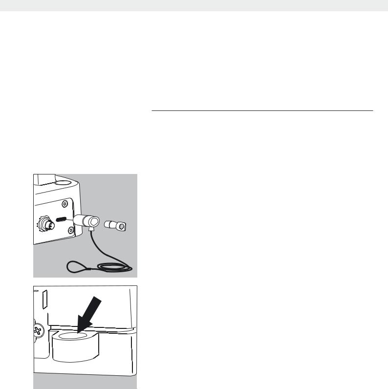
Balances with a readability of ) 1 μg
To fasten an antitheft locking device, use the lug located on the back of the weigh cell.
Cubis MSA User Manual |
19 |
|
|

Getting Started
Leveling the Balance, Setting the Level Indicator
R |
|
|
L |
h Leveling the balance compensates for slant or unevenness at the place |
|
|
|
|
|
|
|
|
|
|
|
|
of installation. The balance must be perfectly horizontal to ensure |
|
|
|
|
|
consistent, reproducible weighing results. All models are equipped with |
|
|
|
|
|
an electronic tilt angle detection feature. If the balance is not level, all |
|
|
|
R |
balance models issue an alert on the display. |
|
|
L |
|
|
Push-button automatic leveling is available on models with motorized |
|
|
|
|
|
|
leveling feet. For models with manual leveling feet, please follow the |
|
|
|
|
|
instructions on the display. |
|
|
|
|
|
|
Leveling the Balance Manually
tThe balance is leveled using both front leveling feet.
tScrew in both back leveling feet (only for models with back leveling feet).
tTurn the two front leveling feet as shown in the illustration until the air bubble is centered within the circle of the level indicator.
L
R
y Normally, several leveling attempts are required.
tUnscrew both back leveling feet until they touch the setup surface (only for models with back leveling feet).
Switching On
t Turn on device via the A key. The following appears on the display:
|
12 |
|
2 |
9 |
3 |
6
yYou can now follow the brief instructions to configure balance settings before beginning weighing operations.
Warm-up Time
yTo deliver precise results, the balance must warm up for at least 30 minutes after initial connection to the power supply. Only after this time will the device have reached the required operating temperature.
When a verified balance used in legal metrology (legal-for-trade applications) is connected to the power, it must warm up for at least two hours before operation.
20 Cubis MSA User Manual
Getting Started
Modifying the Balance
Setting Up the Display and Control Unit at the Place of Use
The display and control unit can be removed for all models to enable the operator to customize the work space.
Removing the Retainer with the Display and Control Unit
1
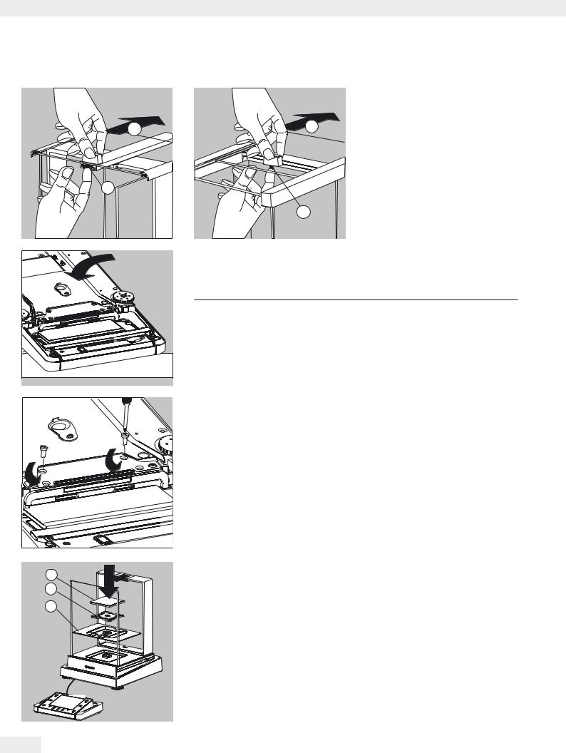
t Remove all items (such as weights) from the draft shield.
2
t Carefully remove all parts as shown in the illustration.
3
1. Weighing pan
2. Pan support (not for MSx225.../MSx125... models) 3. Shield plate/Draft shield
t Keep all parts in a safe place.
t Remove the panels (right and left).
Models with the analytical draft shield:
1.Press on the locking tab.
2.Remove the panel.
Models with the milligram draft shield: 1. Press on the locking tab.
2. Remove the panel.
t Keep all parts in a safe place.
1
1
2
2
Cubis MSA User Manual |
21 |
|
|
Getting Started
t Remove the upper draft shield
|
|
panel. |
2 |
Models with the analytical draft shield |
|
2 |
(left illustration). |
|
|
||
|
1. |
Press on the locking tab. |
|
2. |
Remove the panel. |
|
Models with the milligram draft shield |
|
1 |
(right illustration): |
|
|
1. |
Press on the locking tab. |
1 |
2. |
Remove the panel. |
|
t Keep all parts in a safe place. |
|
t Turn over the balance and place it on a soft surface. |
||
3Exercise caution to avoid breaking the glass on models with a draft shield.
t Use a 2.5 mm Allen wrench to remove the two screws from the display and
|
|
control unit retainer bracket. |
|
t Remove the display and re-insert both screws back into their holes. |
|
|
t Lengthen the cable and position the display and control unit as desired. |
|
|
t Turn the balance over again and place it on an even surface. |
|
|
t Carefully place all parts on the balance. |
|
3 |
1. |
Shield plate/Draft shield |
2 |
2. |
Pan support (not for MSx225.../MSx125... models) |
|
3. |
Weighing pan |
1 |
|
|
22 Cubis MSA User Manual

Getting Started
|
t |
Replace the upper and side shield panel. |
1 |
1. |
Upper draft shield panel |
|
2. |
Right draft shield panel |
|
3. |
Left draft shield panel |
3
2
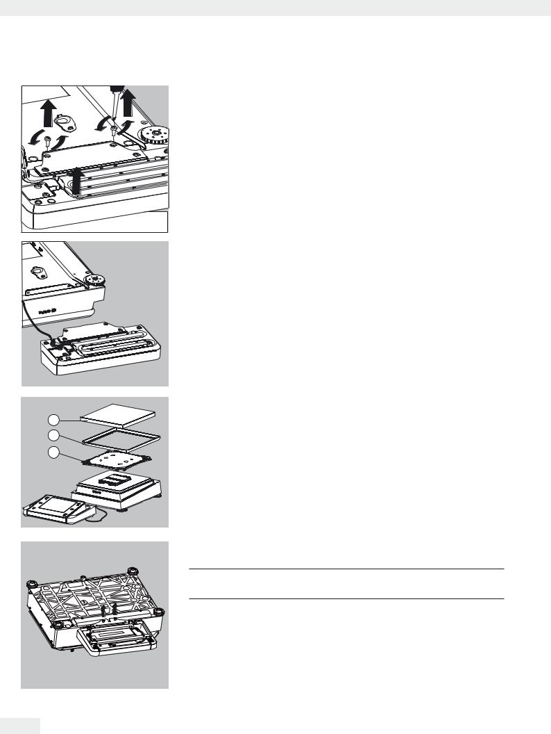
Removing the Display and Control Unit from Precision Balances with a Weighing
Range of up to 15 kg
t Carefully remove all parts as shown in the illustration.
1
|
1. |
Weighing pan |
2 |
2. |
Shield plate/Draft shield |
|
3. |
Pan support |
3
t Keep all parts in a safe place.
t Turn over the balance and place it on a soft surface.
|
|
|
|
|
|
|
Cubis MSA User Manual |
23 |
|
|
|
Getting Started
t Remove the two retaining screws.
t Remove the display and re-insert both screws back into their holes.
t Carefully pull the cable connected between the display and control unit from the retainer.
t Determine the required cable length.
|
t |
Return the balance to an upright position and fit the parts onto the balance. |
3 |
1. |
Attach the pan support. |
2 |
|
|
|
2. |
Shield plate (only for models with a readability of 10 mg) |
1 |
|
|
|
3. |
Weighing pan |
|
t |
Level the balance. |
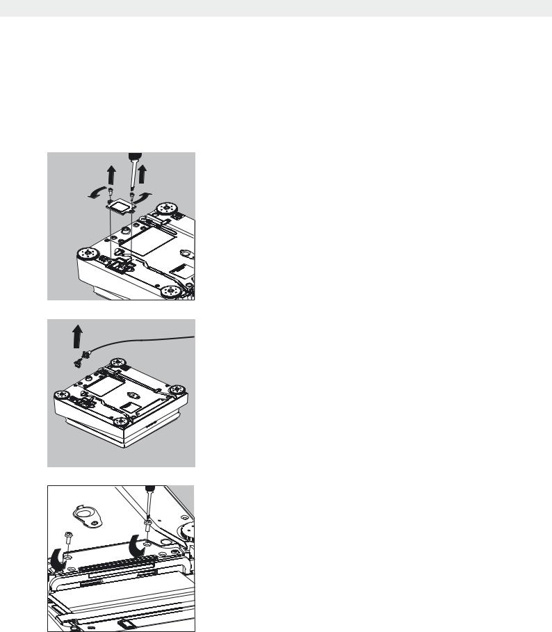
Removing the Display and Control Unit from Models with a Weighing Range of 20 kg or more
3 Remove the weighing pan before unscrewing the control unit, so that the weighing pan does not fall and cause injury.
t Turn over the balance so that the pan side is facing down. t Remove the two fixing screws using a screwdriver.
t Remove the control unit and re-insert both screws into their holes. t Carefully remove the connection cable from its holder.
y Long connection cables should only be installed by a Sartorius technician.
24 Cubis MSA User Manual
Getting Started
Semi-microbalances: Attaching the Display and Control Unit to the Electronics Module (MSx225.../MSx125... models)
The display and control unit can also be attached to the electronics module if required for operation.
t Turn over the balance and place it on a soft surface.
Remove the connection cable from the cable channel:
t Remove two screws from beneath the weigh cell and detach the plate.
tRemove the connection cable plug.
tThen reattach the plate to the slot.
tRemove the display and control unit from the weigh cell: Remove two retaining screws.
tRemove the display and control unit.
Cubis MSA User Manual |
25 |
|
|