

ASP.NET 2.0 Everyday Apps For Dummies (2006)
.pdfChapter 1: Designing ASP.NET 2.0 Applications |
27 |
Suppose the store gives a different discount percentage for each category of product, and the Products and Categories tables are designed like this:
Product
Product ID
Category ID
Name
Price
Image file
Discount Percent
Categories
Category ID
Name
Here, the Discount Percent column depends not on the Product ID column, but on the Category ID column. Thus the table is not in 3NF. To make it 3NF, you’d have to move the Discount Percent column to the
Categories table.
Step 5: Denormalize the database
What?! After all that fuss about normalizing the data, now I’m telling you to de-normalize it? Yes — sometimes. Many cases occur in which a database will operate more efficiently if you bend the normalization rules a bit. In particular, building a certain amount of redundancy into a database for performance reasons is often wise. Intentionally adding redundancy back into a database is called denormalization — and it’s perfectly normal. (Groan.)
Here are some examples of denormalization you might consider for the
Pirate Supply Store database:
Restoring the Subtotal column to the Orders table so the program doesn’t have to retrieve all the Line Items rows to calculate an order total.
Adding a Name field to the Line Items table so the program doesn’t have to retrieve rows from the Products table to display or print an order.
Adding the customer’s name and address to the Orders table so that the application doesn’t have to access the Customers table to print or display an order.
Adding the Category Name to the Products table so the application doesn’t have to look it up in the Categories table each time.

28 |
Part I: Introducing ASP.NET 2.0 Application Development |
In each case, deciding whether to denormalize the database should depend on a specific performance tradeoff — updating the redundant data in several places versus improving the access speed.
Step 6: Pick legal SQL names
All through the data-design process, I use names descriptive enough that I can remember exactly what each table and column represents. However, most SQL dialects don’t allow tables with names like Line Items or columns with names like Product ID or Discount Percent, because of the embedded spaces. At some point in the design, you’ll have to assign the tables and columns actual names that SQL allows. When picking names, stick to these rules:
No special characters, other than $, #, and _.
No spaces.
No more than 128 characters.
Shorter names are better, as long as the meaning is preserved. Although you can create names as long as 128 characters, I suggest you stick to names with 15 or fewer characters.
Step 7: Draw a picture
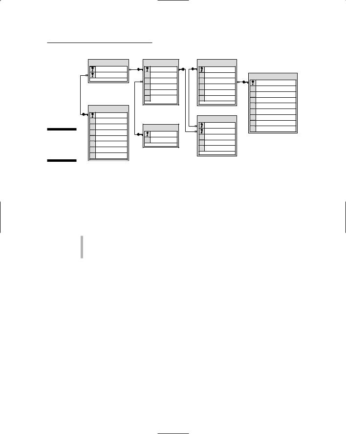
Computer professionals love to draw pictures, possibly because it’s more fun than real work, but mostly because (as they say) a picture is worth 1,024 words. So they often draw a special type of diagram — an Entity-Relationship Diagram (ERD) — when creating a data model. Figure 1-1 shows a typical ERD. Visual Studio 2005 includes a handy feature that automatically creates these diagrams for you.
The ERD shows each of the tables that make up a database and the relationships among the tables. Usually you see the tables as rectangles and the relationships as arrows. Sometimes, the columns within each table are listed in the rectangles; sometimes they aren’t. Arrowheads are used to indicate one-to-one, one-to-many, many-to-one, and many-to-many relationships. Other notational doodads may be attached to the diagram, depending on which drawing school the database designers attended — and whether they’re using UML (more about that shortly).
That’s it for the steps needed to design relational databases. In the next section, I describe another important aspect of application design: designing the various objects that will make up the application.
|
|
Chapter 1: Designing ASP.NET 2.0 Applications |
29 |
||
|
ProductVendor |
Products |
Orders |
|
|
|
ProductID |
ProductID |
OrderNumber |
|
|
|
VendorID |
Name |
Date |
Customers |
|
|
|
CategoryID |
CustomerEmail |
|
|
|
|
|
|||
|
|
Description |
Shipping |
|
|
|
|
LastName |
|
||
|
|
Price |
Tax |
|
|
|
|
FirstName |
|
||
|
|
ImageFile |
Total |
|
|
|
|
Address |
|
||
|
|
|
|
|
|
|
Vendors |
|
|
City |
|
|
|
|
State |
|
|
|
VendorID |
|
|
|
|
|
|
LineItems |
ZipCode |
|
|
|
Name |
|
|
||
|
|
PhoneNumber |
|
||
|
|
OrderNumber |
|
||
|
Address |
Categories |
|
||
|
CreditCardNumber |
|
|||
|
ProductID |
|
|||
Figure 1-1: |
City |
CategoryID |
|
|
|
Price |
|
|
|||
State |
|
|
|||
Name |
|
|
|||
A typical |
ZipCode |
|
Quantity |
|
|
ERD. |
PhoneNumber |
|
Item Total |
|
|
|
|
|
|
||
|
|
|
|
|
|
Designing Objects
The Microsoft .NET Framework is inherently object-oriented, so all ASP.NET applications are object-oriented applications. At minimum, each Web page that makes up the application is represented as two classes, as described by the Model-View-Controller (MVC) pattern:
The view defines the appearance of the page.
The model-controller represents the methods called to handle events, such as when the user clicks a button or selects an item from a drop-down list.
Many ASP.NET applications need additional classes to represent other types of objects. As a result, you might find yourself defining objects that represent business objects, or even some that implement business rules. Then you can write C# or VB code to implement those objects.
The task of designing these objects boils down to deciding what classes the application requires and what the public interface to each of those classes must be. If you plan your classes well, implementing the application is easy; plan your classes poorly, and you’ll have a hard time getting your application to work.
Diagramming Classes with UML
Since the beginning of computer programming, programmers have loved to create diagrams of their programs. Originally they drew flowcharts, graphic representations of a program’s procedural logic (the steps it took to do its job).
30 |
Part I: Introducing ASP.NET 2.0 Application Development |
Flowcharts were good at diagramming procedures, but they were way too detailed. When the Structured Programming craze hit in the 1970s, programmers started thinking about the overall structure of their programs. Before long, they switched from flowcharts to structure charts, which illustrate the organizational relationships among the modules of a program or system.
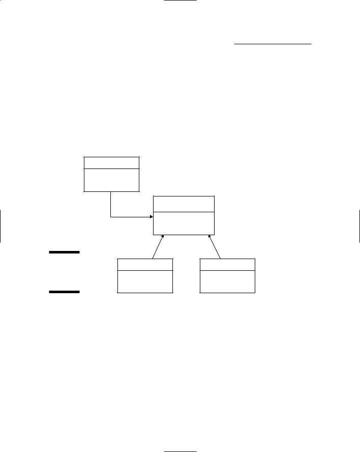
Now that object-oriented programming is the thing, programmers draw class diagrams to illustrate the relationships among the classes that make up an application. For example, the simple class diagram shown in Figure 1-2 shows a class diagram for a simple system that has four classes. The rectangles represent the classes themselves; the arrows represent relationships among classes.
Database
«abstract»
Person
Figure 1-2: |
Customer |
Employee |
|
A simple |
|||
|
|
||
class |
|
|
|
diagram. |
|
|
You can draw class diagrams in many ways, but most programmers use a standard diagramming approach called UML (which stands for Unified Modeling Language) to keep theirs consistent. The class diagram in Figure 1-2 is a simple example of a UML diagram; they can get much more complicated.
The following sections describe the details of creating UML class diagrams. Note that these sections don’t even come close to explaining all the features of UML. I include just the basics of creating UML class diagrams so that you can make some sense of UML diagrams when you see them, and so that you know how to draw simple class diagrams to help you design the class structure for your applications. If you’re interested in digging deeper into UML, check out UML 2 For Dummies by Michael Jesse Chonoles and James A. Schardt (Wiley).

Chapter 1: Designing ASP.NET 2.0 Applications |
31 |
Drawing classes
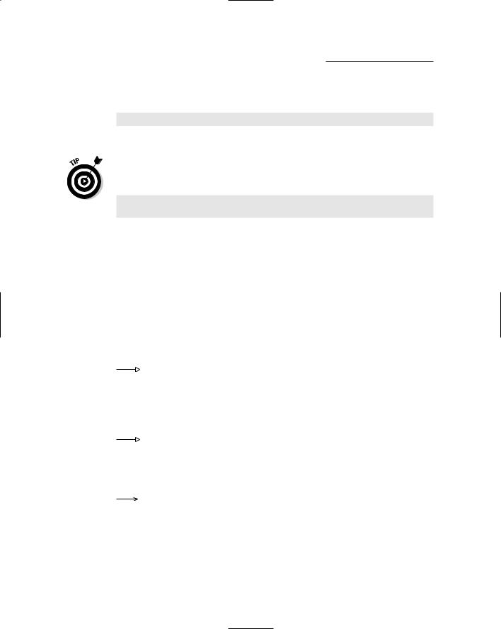
The basic element in a class diagram is a class — drawn as a rectangle in UML. At minimum, the rectangle must include the class name. However, you can subdivide the rectangle into two or three compartments that can contain additional information about the class, as shown in Figure 1-3.
CustomerDB
+ConnectionString
+ConnectionStatus
+GetCustomer
+UpdateCustomer
+DeleteCustomer
Figure 1-3: +AddCustomer
A class. +GetAllCustomers
The middle compartment of a class lists the class variables; the bottom compartment lists the class methods. You can precede the name of each variable or method with a visibility indicator — one of the symbols listed in Table 1-1 — although actual practice commonly omits the visibility indicator and lists only those fields or methods that have public visibility. (Visibility refers to whether or not a variable or method can be accessed from outside of the class.)
Table 1-1 |
Visibility Indicators for Class Variables and Methods |
Indicator |
Description |
+ |
Public |
|
|
- |
Private |
|
|
# |
Protected |
|
|
If you want, you can include type information in your class diagrams — not only for variables, but for methods and parameters as well. A variable’s type is indicated by adding a colon to the variable name and then adding the type, as follows:
connectionString: String
A method’s return type is indicated in the same way:
getCustomer(): Customer
32 |
Part I: Introducing ASP.NET 2.0 Application Development |
Parameters are specified within the parentheses; both the name and type are listed, as in this example:
getCustomer(custno: int): Customer
Note: The type and parameter information are often omitted from UML diagrams to keep them simple.
Interfaces are drawn pretty much the same way as classes, except the class name is preceded by the word interface, like this:
«interface»
ProductDB
Note: The word interface is enclosed within a set of double-left and doubleright arrows. These double arrows are often called chevrons and can be accessed in Microsoft Word via the Insert Symbol command.
Drawing arrows
Besides rectangles to represent classes, class diagrams also include arrows that represent relationships among classes. UML uses various types of arrows; this section shows a basic set of them.
A solid line with a hollow, closed arrow at one end represents inheritance:
The arrow points to the base class.
A dashed line with a hollow, closed arrow at one end indicates that a class implements an interface:
The arrow points to the interface.
A solid line with an open arrow indicates an association:
An association simply indicates that two classes work together. It may be that one of the classes creates objects of the other class, or that one class requires an object of the other class to perform its work. Or perhaps instances of one class contain instances of the other class.
You can add a name to an association arrow to indicate its purpose. For example, if an association arrow indicates that instances of one class create objects of another class, you can place the word Creates next to the arrow.

Chapter 2
Using Visual Studio 2005
In This Chapter
Using Visual Web Developer to create a basic Hello World application
Adding additional features to the Hello World application
Using the debugger to find and correct errors
Deploying an ASP.NET application
Technically, everything you need to create ASP.NET 2.0 applications is free. You can download the .NET Framework from Microsoft’s Web site for
free, most versions of Windows come with the IIS Web server, and the only development environment you need is Notepad.
But building ASP.NET applications with Notepad is kind of like cutting down your own trees and milling your own lumber to build a doghouse. Yes, you can do it, but it’s much easier to go to Home Depot and buy the two-by-fours already cut.
Likewise, ASP.NET applications are much easier to develop if you use Visual Studio, Microsoft’s development environment for creating .NET applications. The least expensive edition of Visual Studio you need if you’re going to create an ASP.NET 2.0 application is Visual Web Developer 2005 Express Edition (also known as VWDE). You can purchase it for about a hundred bucks — even less if you’re a student. Although you can use one of the more expensive versions of Visual Studio 2005, VWDE is sufficient for the applications presented in this book.
This chapter walks you step-by-step through the process of creating a simple ASP.NET 2.0 application using VWDE. Before you get started, you should first install VWDE according to the instructions that come with it. After you’ve installed VWDE, you’re ready to go.
34 |
Part I: Introducing ASP.NET 2.0 Application Development |
If you’re using one of the professional editions of Visual Studio, the steps for creating Web applications are the same. However, you can’t create Web applications using one of the language-specific Express editions of Visual Studio such as Visual Basic 2005 Express Edition or Visual C# 2005 Express Edition. Those editions can only create Windows-based applications.
Creating a Basic Hello World Application
Many classic programming books begin with a simple Hello World application that displays the text Hello, World! on the screen. Because I’d like this book to become a classic, we start with a Hello World program and develop it step by step, adding new features as we go.
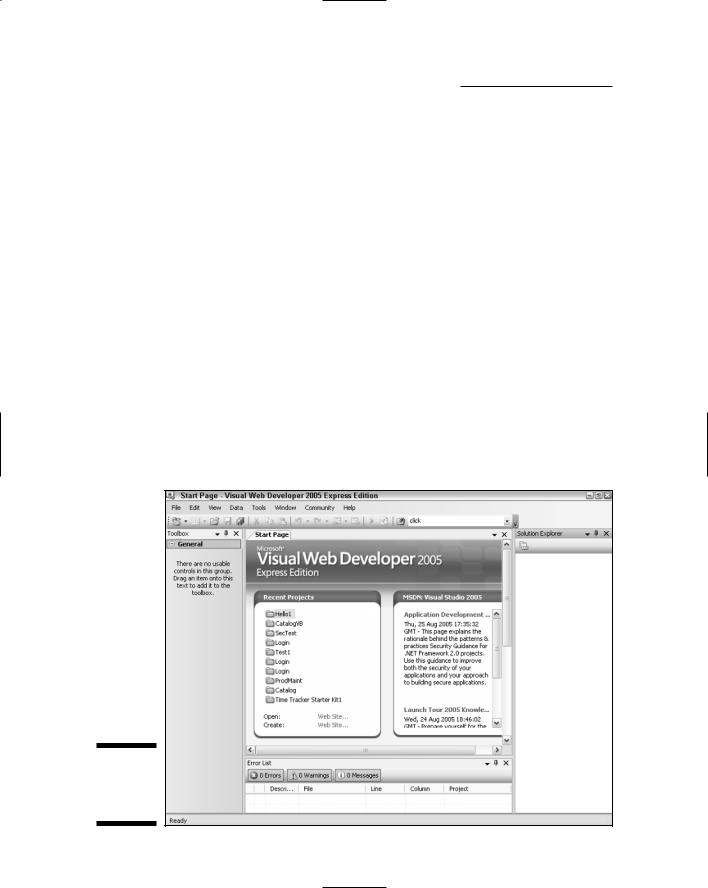
To get started, fire up Visual Web Developer. The Start Page will appear, as shown in Figure 2-1. As you can see, this page gives you fast access to the projects you’ve been recently working on. You can click one of the links in the Recent Projects section to open a project.
The Start Page also shows recent information from Microsoft’s MSDN site, which contains useful information for developers. If any of these items interests you, click it to read more.
Figure 2-1:
Visual Web
Developer’s
Start page.

Chapter 2: Using Visual Studio 2005 |
35 |
Creating a new Web site
To create a new Web site, follow these steps:
1.Choose File New Web Site.
This brings up the New Web Site dialog box, as shown in Figure 2-2. This dialog box lists the templates available for creating Web sites. By default, the ASP.NET Web Site template is selected. That’s the one you want to use to create a basic Web site.
Figure 2-2:
The New Web Site dialog box.
2.Choose File System from the Location drop-down menu.
The Location drop-down list enables you to choose one of three types of Web sites you can create:
•File System: This option creates a Web site that’s run by Visual Web Developer’s built-in Web server, which is called the ASP.NET Development Server. For the applications in this book, file system Web sites are adequate.
•HTTP: This option creates a Web site on an IIS server (IIS refers to Internet Information Services, Microsoft’s Web server). The IIS
server can run on your own computer or another server computer you have access to. This is the option used most often for professional Web site development.
36 |
Part I: Introducing ASP.NET 2.0 Application Development |
•FTP: This option creates a Web site on a remote IIS server to which you don’t have HTTP access. It uses the File Transfer Protocol
(FTP) to upload your Web site files to the server.
FTP sites are used mostly when you’re working with a hosting service to host your site.
3.Type the name and location for your Web site in the path text box.
By default, file system Web sites are created in My Documents\Visual
Studio 2005\WebSites. You’ll have to scroll to the end of this long path to type the name of your Web site at the end of this path.
You can use the Browse button to bring up a dialog box that enables you to browse to the location where you want to create the Web site.
4.Choose the language you want to use from the Language drop-down menu.
The choices are Visual Basic, Visual C#, and Visual J#.
5.Click OK.
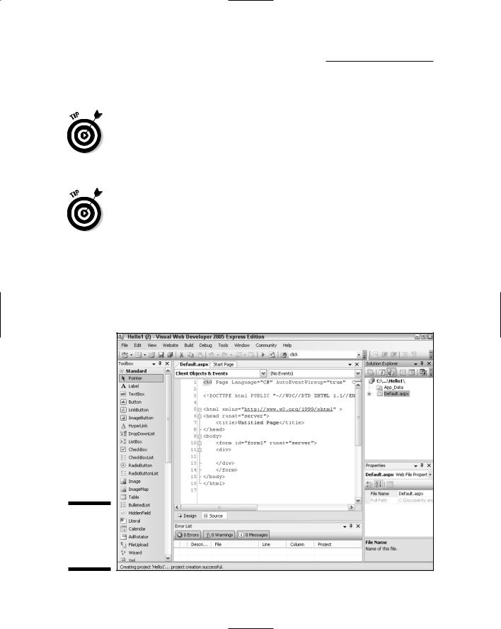
Visual Web Developer grinds and whirs for a moment as it creates your Web site. When it’s finished, a screen similar to the one shown in Figure 2-3 appears. Here, the Default.aspx page is opened in Source view.
Figure 2-3:
A newly created Web site (C#).