

Emerging Tools for Single-Cell Analysis
.pdf6 |
Cell-Sorting Technology |
F i g . 1.3A. An approach for sorting into a microwell plate. The waste stream is deflected and the sorted stream drops into the plate. The plate is moved by a computer-controlled X–Y stage.
tions produce uniformly sized microdroplets at a fixed distance from the exit orifice. A stable droplet generator, combined with the previously described flow system, will make the transit time, or delay, between the time a particular cell is measured in the laser beam and the time it arrives at the last attached stream undulation a nearly constant value.
A desired cell is sorted by waiting for the cell to arrive in the last attached undulation and then applying a charge of duration T (the period of the transducer drive signal), synchronized with the droplet formation. If a positive charge is applied, then the undulation, already depleted of electrons, will carry a positive charge on its surface after it has broken free. The charge will reside on the surface of the droplet and will not affect the cell encased in the droplet. The now-free charged droplet then passes through an electric field produced by the potential difference between the deflection plates D (Fig. 1.1). The resulting electromagnetic force steers the droplet along a predictable trajectory based on the geometry of the plates, the value of the potential difference, and the amplitude of the charge applied to the droplet. Care must be taken to eliminate air currents and any other sources of electromagnetic fields in the collection area to ensure proper droplet trajectory. Cells are usually collected into tubes

Droplet Cell Sorters |
7 |
F i g . 1.3B. Four-way sorting configuration. Cell trajectory is controlled by adjusting the amplitude of the charge placed on the stream.
containing appropriate growth media, at collection points C (Fig. 1.1). Unsorted droplets receive no charge and pass straight through to waste or to a collection vessel.
There are several variations on stream deflection based on the collection scheme for the sorted fraction. Figure 1.3A shows a typical orientation for sorting directly into microwell plates. This is the inverse of the traditional bidirectional arrangement previously described. The stream is continuously charged until a droplet is to be sorted. The charge is then removed and the stream returned to the ground potential, causing the sorted microdroplets to fall straight down into the well of the plate. The plate rests on an X–Y stage and indexes its position under computer control. This arrangement is used routinely for selecting cells for cloning and for isolating cells for polymerase chain reaction (PCR) amplification. This method requires a very accurate sorted-droplet trajectory since the diameter of the target in a conical bottom microwell plate can be as small as 1 mm in some cases. Figure 1.3B shows a four-way sorting configuration where the two streams formed on each side are produced by discrete variations in the sort charge amplitude. The advantage of this arrangement is the increased number of sorted fractions that can be collected.
The process of droplet cell sorting can then be summarized by the following sequence of operations: (1) measure the cell; (2) classify the cell as to its sort status;
8 |
Cell-Sorting Technology |
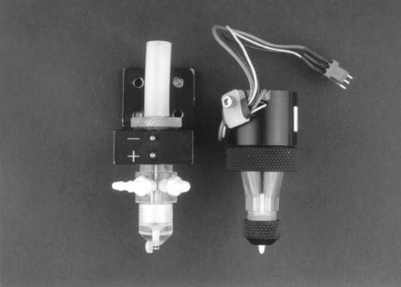
F i g . 1.4. Droplet generator assemblies from two commercial cell sorters: left, Beckman-Coulter instrument; right, Cytomation instrument.
(3) wait for the cell to arrive at the last undulation; (4) properly charge the undulation to accomplish the sort operation; and (5) deflect and then collect the sorted droplets.
Droplet Generation
Proper design and maintenance of the droplet generator are essential for reliable performance of a droplet cell sorter. Droplet generators often consist of a flow cell or nozzle attached in some manner to a piezoelectric device. The droplet generator assemblies for two commercial cell sorters are shown in Figure 1.4. Figure 1.4A (left) shows the generator used on the EPICS Altra (Beckman-Coulter) and Figure 1.4B (right) shows the droplet generator used on the MoFlo MLS 2000 (Cytomation). Both generators incorporate a piezoelectric transducer located above their respective flow cell assemblies. For any droplet generator, nozzle diameter, sheath pressure, and droplet generation frequency must all be properly matched to ensure stable droplet generation. For convenience, the relationship and codependencies of these variables are described briefly below. More detailed derivations and discussion of the properties of droplet generators appear in Chapter 2.
As previously discussed, stream undulations are initiated by introducing lowamplitude modulation of the stream velocity. This is accomplished by either coupling acoustic energy to the nozzle tip or directly modulating sheath pressure. The wavelength of these undulations is given by:
Droplet Cell Sorters |
9 |
|
λ = v |
|
f |
where |
λ = undulation wavelength |
|
v = stream velocity |
|
f = modulation frequency |
The hydrodynamic properties of the system govern the conditions necessary for stable droplet formation. The details of the fluid dynamics that govern this system are beyond the scope of this text, but the topic is covered in detail elsewhere (Kachel et al., 1977, 1990). In short, droplets form due to forces arising from the surface tension of the stream and perturbations induced by the generator. The range of droplet generation frequencies (∆f ) that will result in stable droplet formation is constrained by the diameter of the stream. Kachel et al. (1990) derive that stable droplet break-off will occur only if λ exceeds the circumference of the stream and thus the circumfer-
ence of the exit orifice. The minimum value for λ (λmin) in terms of the exit orifice diameter d is given by
λmin = πd
Kachel et al. proceed to derive the optimal value for λ (λopt) to be
λopt = 4.5d
It follows from the previous equations that the maximum and optimal droplet generation frequencies for a droplet sorter are given by
fmax |
= v |
fopt |
= v |
|
πd |
|
4.5d |
The optimal droplet generation frequency for a given nozzle diameter is therefore dictated by the jetting stream velocity. In Chapter 2 van den Engh develops the relationship of velocity to sheath pressure, which yields
|
v = |
2P |
1/2 |
fopt |
(2P/ρ)1/2 |
|
|
= |
|||
|
|
ρ |
|
|
4.5d |
where |
v = jet velocity |
|
|
||
|
d = jet diameter |
|
|
||
|
ρ = density |
|
|
||
P = pressure drop across the exit orifice
For nozzle diameters and pressures typical for cell sorters, the optimal droplet generation frequency is therefore a function of the nozzle diameter and the pressure drop across the exit orifice of the nozzle.
The coaxial flow system employed by droplet cell sorters requires that nonturbulent flow be maintained. This requirement can limit the maximum jet velocity and thereby the maximum droplet generation frequency. For a parabolic velocity profile,
10 |
Cell-Sorting Technology |
this critical operating point can be estimated from the Reynolds number (Re) for the orifice–sheath fluid combination in use. For a flowing stream of phosphate-buffered saline (PBS) with a parabolic velocity profile, the probability that laminar flow may break down is significant for Re > 2300 (Kachel et al., 1990). The equation for the Reynolds number is given as
|
|
|
dρv |
|
|
|
Re = η |
where |
d |
= |
nozzle diameter (cm) |
|
ρ |
= |
fluid density (g/cm3) |
|
v |
= |
average fluid velocity (cm/s) |
|
η = |
fluid viscosity (g/cm s) |
|
The short path length in the flow nozzle may prevent full parabolic flow from developing (Lindmo et al., 1990), and therefore nonturbulent flow may be sustainable for higher Re values. However, the impact of temperature on viscosity and ultimately on the maximum allowable jet velocity is important for both large-particle and highspeed cell-sorting applications.
Droplet Sorter Flow Cells
A key component of the droplet generator is the nozzle that produces the jetting stream. It must be large enough to accommodate the largest particles in the sorting suspension, it must maintain the stream position for laser intersection, and it must effectively transfer energy from the generator’s transducer to the stream. The diameter of the orifice in a droplet cell sorter nozzle typically ranges 50–150 µm. Cells entering the undulating stream will introduce random perturbations in the stream that may temporarily alter the droplet break-off from the location established without flowing cells. The perturbations become more significant as the cell diameters approach the diameter of the stream (i.e., the orifice diameter). This manifests on a droplet sorter as instability, or fanning of the sorted droplet stream. Observations reported by Bonner et al. (1972) indicate that a 5 : 1 ratio between the sorting orifice diameter and the average cell diameter results in stable droplet generation.
Shown in Figure 1.5 are several different nozzle assemblies used in commercial droplet sorters (5A, Beckman-Coulter; 5B, Becton Dickinson; 5C, CytomationCoulter). There are many variations in shape and fabrication materials; however, one major difference among these nozzles is whether the laser intersection occurs in a quartz channel or in the jetting stream in air. The jet-in-air nozzles are relatively easy to construct and offer the simplest transition to laminar flow. Optically, the jetting stream acts as a short-focal-length cylindrical lens. In addition, undulations superimposed on the stream by the droplet generator add to the refractive effect. Flow cells that place the laser intersection in a quartz channel, such as the one shown in Figure 1.5A, offer improved optical performance. The quartz flow cell shown in Figure 1.5A (left) is based on a design described by Watson (1989) and further developed by Larry Arnold (personal communication) at the University of North Carolina. It con-

Droplet Cell Sorters |
11 |
F i g . 1.5. Examples of flow cells used on three commercial sorting systems (left to right): (A) Beck- man-Coulter; (B) Becton-Dickinson; (C) Cytomation. Laser intersection for A is in quartz. Laser intersection for B and C is in the jetting stream.
sists of a 1-mm-long, 100-µm-square channel with a lens bonded to one face of the quartz. The integral lens couples light from the laser intersection point to the fluorescence collection system, increasing the effective numerical aperture, thus improving the fluorescence sensitivity of the instrument. This type of flow cell has made possible the use of lower-power lasers for cell sorting. The lensing effect caused by the stream, as described above for jet-in-air systems, is eliminated and the quartz provides a better index-of-refraction match, substantially reducing the scatter at the interface points. Quartz sorting flow cells have been successfully employed and can improve fluorescence collection efficiency and light scatter resolution. On the other hand, they also chip easily, are more difficult to unclog, and are more expensive to replace than their jet-in-air counterparts.
Droplet Charging
The trajectory of the sorted droplets is adjusted on most droplet cell sorters by varying the amplitude of the charging pulse delivered to the stream while maintaining a constant potential difference of 3–5 kV between the deflection plates. Left and right sorting is accomplished by switching the polarity of the charge pulse. Multiple sorted streams can be obtained by establishing a unique charge amplitude–polarity combination for each sorted fraction. It is essential that the charge pulse be applied in phase
12 |
Cell-Sorting Technology |
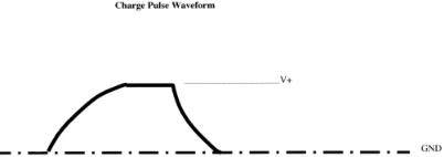
with droplet generation. The correct phase relationship will produce the maximum droplet deflection, and most droplet sorters provide a method for making this phase adjustment. Figure 1.6 shows the waveform obtained from a commercial cell sorter for a charge pulse applied to sort a single droplet. The pulse is shaped in this manner to correct for charge coupling that occurs between the last undulation and the preceding free charged droplet (Lindmo et al., 1990). Other electromagnetic fields or charged surfaces in the vicinity can affect the trajectory of the charged droplets. Care should be taken to choose collection vessels that will not accumulate a surface charge or to properly ground them.
The arrival times of cells at the laser interrogation point (Fig. 1.1) are expected to be random, independent events and may therefore be described by a Poisson probability distribution. It follows, then, that the relative phase difference between cell arrival times and the synchronous formation of droplets will be uniformly distributed. This means that some droplets will have cells positioned very near the boundaries separating them from adjacent droplets. For cells near the edge of a droplet period when measured, uncertainty regarding the time of flight to the break-off point results in uncertainty as to which of two adjacent free droplets will actually contain the cell. In this case, to achieve a high probability of sorting the cell it is necessary to sort both of the droplets in question, that is, both the droplet that corresponds to the detection time and the adjacent droplet closest (either before or after) to the detection time point. This result has been achieved in some instruments by sorting a three-droplet set. However, sorting three droplets is unnecessary if the sort decision system is designed to use the phase of the cell’s arrival time to select the correct droplet pair. Sorting the correct two-droplet pair as described will increase the probability that the identified cell actually makes it into the collection tube. Unfortunately, it also increases the time during which a contaminating cell must be avoided. For this reason, single-droplet sorts will always provide the highest sorting rates.
Cell Queueing and Coincidence
The undulating stream can be thought of as a short queue that advances with the formation of each droplet. As each droplet advances, the sort decision system must
F i g . 1.6. Typical waveform for the voltage pulse used to charge a sorted drop or frame of sorted droplets. This pulse shape corrects for the coupling charge between adjacent droplets.
Droplet Cell Sorters |
13 |
classify or define the state of the newest queue entry. If we define a contaminating cell as either a cell identified as unselected or a cell detected but unidentified, then the states of interest for a simple one-direction sort would be (1) empty; (2) containing one or more selected cells; (3) containing one or more contaminating cells; or (4) containing one or more selected cells and one or more contaminating cells. When an undulation advances down the queue to the position of last attached undulation, the sorting system performs the prescribed sorting operation for that state. State 4, as described above, is referred to as coincidence. A droplet with state 4 cannot be sorted without also including a contaminating cell. The states become more complicated if we introduce the recognition of the phase location of the cells in the droplet period. States 2, 3, and 4 might be divided into three substates indicating whether the corresponding cells were near the front edge, near the back edge, or centered in the droplet period. In this case, the sort decision system would need to look not only at the state of last attached undulation but also at the states of the previous droplet and the next undulation before deciding on a sort operation.
Electronic Processing of a Cell Measurement
As a labeled cell traverses the focused laser beam, the instrument photodetectors produce electronic pulses proportional to the intensity of the light scatter and fluorescence emissions. Each detector in use produces its own pulse similar to that shown in Figure 1.7. In some cases, analog processing is done on the original pulse to produce secondary pulses having peak amplitudes proportional to the integral, pulse width, or logarithm of the original pulse. After amplification these pulses are used by the sorting electronics to detect the arrival of a cell and then to classify the cell as to its sorting status. Two basic parameters define the theoretical performance of a particular electronic sorting system: the detection time tdet and the cycle time tcy of the system. As illustrated in Figure 1.7, the detection time starts with the initial detection of cell arrival (pulse amplitude rises above a lower threshold) and ends with the departure of the cell (pulse amplitude passes below a threshold). If another cell arrives during the detection time (as depicted in Fig. 1.7B), it will not be independently recognized. Instead, the electronics will assume that the combination of the cell emissions represent a single cell, and thus the cells will be misclassified. The cycle time starts at the same time as the detection time, but it continues until the electronic system is ready, or rearmed to receive the next pulse. A second cell arriving after tdet but before tcy (as depicted in Fig. 1.7C) will be detected as present but will remain unclassified because the electronics are busy. The difference between tcy and tdet is usually referred to as the system dead time.
Detection time (typically 1–2 µs on droplet sorters) is primarily determined by the width of the pulse driving the sorting system. For high-speed applications it is essential to minimize pulse width by not using integral pulses and by reducing the laser beam height to approximately one cell diameter. Cycle time (typically 4–10 µs on droplet sorters) is dictated by the electronics system design. Figure 1.7 represents a relatively simplistic example of event detection; other more complex schemes have

14 |
Cell-Sorting Technology |
F i g . 1.7. Three examples of pulses detected and then processed by the cell-sorter electronic system. (A) Pulse arrives and is processed with no coincidence. (B) Two pulses arrive (dotted lines) within tdet. The pulses cannot be resolved by the electronics and are treated as one longer pulse. This will result in the misclassification of these cells. (C) Another pulse arrives during the dead time (after tdet but within tcy). The first pulse is classified. The second pulse is not classified but the coincidence detection system records its presence and can abort the sort decision if necessary. The condition in panel C impacts efficiency and recovery. The condition in panel B can impact purity.
been implemented (van den Engh and Stokodijk, 1989; Dean et al., 1985; Cupp et al., 1984). Given a well-designed, stable droplet generation and sorting system, the performance of a droplet cell sorter will ultimately be limited by its effective tdet and tcy values.
Defining Cell Sorter Performance
Cell sorter performance is usually defined in terms of efficiency, purity, recovery, and yield. These four terms are defined below in terms of the following variables:
xtot |
Total number of cells that pass through the laser(s) |
xin |
Number of cells that should satisfy the sort criteria and that pass through the |
|
laser(s) |
xsrt |
Number of cells that the instrument actually attempts to sort |
xtub |
Number of cells that satisfy the sort criteria and that can be found in the collec- |
|
tion tube |
xcon |
Number of contaminating cells or cells which do not satisfy the sort criteria and |
|
that can be found in the collection tube |
Droplet Cell Sorters |
15 |
Sorting performance terms are defined as:
Sort efficiency (E) in %—sorts attempted as a percent of targeted cells in sample:
E = xsrt × 100
xin
Sort purity (P) in %—targeted cells collected as a percent of total cells collected:
P = xtub × 100
xtub + xcon
Sort recovery (R) in %—targeted cells collected as a percent of sorts attempted:
R = xtub × 100
xsrt
Sort yield (Y) in %—targeted cells collected as a percent of targeted cells in sample:
Y = xtub × 100
xin
Predicting Cell Sorter Performance
Accurate predictions of cell sorter performance can be problematic due to the many independent variables involved. Assume a stable droplet generator is properly phased with the sort charging pulses, a fluidic system delivers cells with Poisson-distributed arrival times, and a sample can be reliably classified by fluorescence emission and neglect targeted cells missed due to arrival within tdet of another cell. Then the sort efficiency, rate, and maximum purity can be estimated using the following expressions, which are developed in detail by Lindmo et al. (1990) and are presented here as a convenient reference.
Sort efficiency (%):
E = exp[-m(1 – a)nT ] × 100
Sorting rate (targeted cells per second):
|
Rs = ma exp(-m(1 – a)nT |
||
Maximum purity (%): |
|
|
|
|
|
|
1 + amtcy |
|
|
Pmax = × 100 |
|
|
|
|
1 + mtcy |
where |
m = |
average analysis rate (cells/s) |
|
|
a |
= |
xin/xtot |
|
n |
= |
number of droplets sorted |
|
T |
= |
period of droplet generator |
|
tcy |
= |
cycle time |