

EISA System
Architecture
Second Edition
MINDSHARE, INC.
TOM SHANLEY
DON ANDERSON
▲
▼▼
Addison-Wesley Publishing Company
Reading, Massachusetts • Menlo Park, California • New York Don Mills, Ontario • Wokingham, England • Amsterdam Bonn • Sydney • Singapore • Tokyo • Madrid • San Juan Paris • Seoul • Milan • Mexico City • Taipei
MindShare, Inc (r)
SINGLE-USER LICENSE AGREEMENT
Please read this document carefully before proceeding. This Agreement licenses this electronic book to you and contains warranty and liability disclaimers. By viewing this book, you are confirming your acceptance of the book and agreeing to become bound by the terms of this Agreement. If you do not wish to do so, immediately return the book to MindShare, Inc.
1. DEFINITIONS
(a) "book or electronic book" means the electronic book covered by this Agreement, and any related updates supplied by MindShare, Inc. The book consists of the encrypted PDF file supplied in electronic form.
2. LICENSE
This Agreement allows the SINGLE END-USER to:
(a)View the book on a computer or a stand-alone ebook viewer.
(b)You may make and distribute copies of the book and electronically transfer the book from one computer to another or over a network.
(c)Certain rights are not granted under this Agreement, but may be available under a separate agreement. If you would like to enter into a Site or Network License, please contact MindShare.
3. RESTRICTIONS
(a)You may not copy screen images of the book, or any portion thereof.
(b)You may not decompile, reverse engineer, disassemble, or otherwise reduce the book to a human-perceivable form.
(c)You may not modify, rent, resell for profit, distribute or create derivative works based upon the book or any part thereof.
(d)You will not export or reexport, directly or indirectly, the book into any country prohibited by the United States Export Administration Act and the regulations thereunder.
(e)The book may not be used in a group viewing environment.
4. OWNERSHIP
The foregoing license gives you limited rights to use the book. You do not become the owner of, and MindShare retains title to, the intellectual property contained within the book, and all copies thereof. All rights not specifically granted in this Agreement, including Federal and International Copyrights, are reserved by MindShare.
5. DISCLAIMER OF WARRANTIES AND OF TECHNICAL SUPPORT:
The book is provided to you on an "AS IS" basis, without any technical support or warranty of any kind from MindShare including, without limitation, a warranty of merchantability, fitness for a particular purpose and non-infringement. SOME STATES DO NOT ALLOW THE EXCLUSION OF IMPLIED WARRANTIES, SO THE ABOVE EXCLUSION MAY NOT APPLY TO YOU. YOU MAY ALSO HAVE OTHER LEGAL RIGHTS WHICH VARY FROM STATE TO
STATE. These limitations or exclusions of warranties and liability do not affect or prejudice the statutory rights of a consumer; i.e., a person acquiring goods otherwise than in the course of a business.
6. LIMITATION OF DAMAGES:
MINDSHARE SHALL NOT BE LIABLE FOR ANY INDIRECT, SPECIAL, INCIDENTAL OR CONSEQUENTIAL DAMAGES OR LOSS (INCLUDING DAMAGES FOR LOSS OF BUSINESS, LOSS OF PROFITS, OR THE LIKE), WHETHER BASED ON BREACH OF CONTRACT, TORT (INCLUDING NEGLIGENCE), PRODUCT LIABILITY OR OTHERWISE, EVEN IF MINDSHARE OR ITS REPRESENTATIVES HAVE BEEN ADVISED OF THE POSSIBILITY OF SUCH DAMAGES. SOME STATES DO NOT ALLOW THE LIMITATION OR EXCLUSION OF LIABILITY FOR INCIDENTAL OR CONSEQUENTIAL DAMAGES, SO THIS LIMITATION OR EXCLUSION MAY NOT APPLY TO YOU. The limited warranty, exclusive remedies and limited liability set forth above are fundamental elements of the basis of the bargain between Mindshare and you. You agree that Mindshare would not be able to provide the book on an economic basis without such limitations.
7. GOVERNMENT END USERS (USA only):
RESTRICTED RIGHTS LEGEND The book is "Restricted Computer Software." Use, duplication, or disclosure by the U.S. Government is subject to restrictions as set forth in this Agreement and as provided in DFARS 227.7202-1(a) and 227.7202-3(a) (1995), DFARS 252.227-7013 (OCT 1988), FAR 12.212(a)(1995), FAR 52.227-19, or FAR 52.227-14, as applicable." Manufacturer: Mindshare, Inc., 4285 Slash Pine Drive, Colorado Springs, CO 80908.
8. GENERAL:
This Agreement shall be governed by the internal laws of the State of Colorado. This Agreement contains the complete agreement between the parties with respect to the subject matter hereof, and supersedes all prior or contemporaneous agreements or understandings, whether oral or written.
All questions concerning this Agreement shall be directed to: Mindshare, Inc., 4285 Slash Pine Drive, Colorado Springs, CO 80908, Attention: Chief Financial Officer.
Mindshare is registered trademark of Mindshare, Inc.
Single-User License Agreement 9/8/00.
Many of the designations used by manufacturers and sellers to distinguish their products are claimed as trademarks. Where those designations appear in this book, and Addison-Wesley was aware of a trademark claim, the designations have been printed in initial capital letters or all capital letters.
The authors and publishers have taken care in preparation of this book, but make no expressed or implied warranty of any kind and assume no responsibility for errors or omissions. No liability is assumed for incidental or consequential damages in connection with or arising out of the use of the information or programs contained herein.
Library of Congress Cataloging-in-Publication Data
Copyright © 1995 by MindShare, Inc.
All rights reserved. No part of this publication may be reproduced, stored in a retrieval system, or transmitted, in any form or by any means, electronic, mechanical, photocopying, recording, or otherwise, without the prior written permission of the publisher. Printed in the United States of America. Published simultaneously in Canada.
Sponsoring Editor: Keith Wollman
Project Manager: Eleanor McCarthy
Production Coordinator: Lora L. Ryan
Cover design: Barbara T. Atkinson
Set in 10 point Palatino by MindShare, Inc.
1 2 3 4 5 6 7 8 9 -MA- 9998979695 First printing, February 1995
Addison-Wesley books are available for bulk purchases by corporations, institutions, and other organizations. For more information please contact the Corporate, Government, and Special Sales Department at (800) 238-9682.

This book is dedicated to my son, Ryan, a ray of sunshine who possesses an incredible amount of that rarest of elements, common sense.

|
Contents |
Contents |
|
Acknowledgments................................................................................................................... |
i |
About This Book |
|
The MindShare Architecture Series..................................................................................... |
1 |
Organization of This Book..................................................................................................... |
2 |
Part One – The EISA Specification .................................................................................. |
2 |
EISA Overview ........................................................................................................... |
2 |
EISA Bus Structure Overview................................................................................... |
2 |
EISA Bus Arbitration.................................................................................................. |
2 |
Interrupt Handling..................................................................................................... |
2 |
Detailed Description of EISA Bus............................................................................. |
3 |
ISA Bus Cycles ............................................................................................................ |
3 |
EISA CPU and Bus Master Bus Cycles .................................................................... |
3 |
EISA DMA................................................................................................................... |
3 |
EISA System Configuration ...................................................................................... |
3 |
Part Two – The Intel 82350DT EISA Chipset ................................................................. |
3 |
EISA System Buses ..................................................................................................... |
3 |
Bridge, Translator, Pathfinder, Toolbox .................................................................. |
3 |
Intel 82350DT EISA Chip Set .................................................................................... |
4 |
Who This Book Is For.............................................................................................................. |
4 |
Prerequisite Knowledge......................................................................................................... |
4 |
Documentation Conventions................................................................................................. |
4 |
Hex Notation...................................................................................................................... |
5 |
Binary Notation.................................................................................................................. |
5 |
Decimal Notation............................................................................................................... |
5 |
Signal Name Representation............................................................................................ |
5 |
Bit Field Identification (logical bit or signal groups) .................................................... |
5 |
We Want Your Feedback ........................................................................................................ |
6 |
Bulletin Board..................................................................................................................... |
6 |
Mailing Address ................................................................................................................ |
6 |
Part One – EISA Specification |
|
Chapter 1: EISA Overview |
|
Introduction .............................................................................................................................. |
9 |
Compatibility With ISA ......................................................................................................... |
10 |
Memory Capacity..................................................................................................................... |
10 |
v
EISA System Architecture |
|
Synchronous Data Transfer Protocol ................................................................................... |
10 |
Enhanced DMA Functions..................................................................................................... |
10 |
Bus Master Capabilities ......................................................................................................... |
11 |
Data Bus Steering .................................................................................................................... |
12 |
Bus Arbitration......................................................................................................................... |
12 |
Edge and Level-Sensitive Interrupt Requests.................................................................... |
12 |
Automatic System Configuration......................................................................................... |
12 |
EISA Feature/Benefit Summary............................................................................................ |
13 |
Chapter 2: EISA Bus Structure Overview |
|
Community of Processors....................................................................................................... |
15 |
Limitations of ISA Bus Master Support.......................................................................... |
16 |
EISA Bus Master Support................................................................................................. |
17 |
EISA System Bus Master Types............................................................................................ |
20 |
Types of Slaves in EISA System ........................................................................................... |
21 |
Chapter 3: EISA Bus Arbitration |
|
EISA Bus Arbitration Scheme ............................................................................................... |
23 |
Preemption................................................................................................................................ |
28 |
Example Arbitration Between Two Bus Masters............................................................... |
29 |
Memory Refresh ...................................................................................................................... |
30 |
Chapter 4: Interrupt Handling |
|
ISA Interrupt Handling Review ........................................................................................... |
33 |
ISA Interrupt Handling Shortcomings................................................................................ |
34 |
Phantom Interrupts ........................................................................................................... |
34 |
Limited Number of IRQ Lines ......................................................................................... |
35 |
EISA Interrupt Handling........................................................................................................ |
35 |
Shareable IRQ Lines .......................................................................................................... |
35 |
Phantom Interrupt Elimination ....................................................................................... |
40 |
Chapter 5: Detailed Description of EISA Bus |
|
Introduction .............................................................................................................................. |
41 |
Address Bus Extension ........................................................................................................... |
43 |
Data Bus Extension.................................................................................................................. |
45 |
Bus Arbitration Signal Group ............................................................................................... |
45 |
Burst Handshake Signal Group............................................................................................ |
48 |
Bus Cycle Definition Signal Group ..................................................................................... |
48 |
Bus Cycle Timing Signal Group ........................................................................................... |
49 |
Lock Signal ............................................................................................................................... |
49 |
Slave Size Signal Group......................................................................................................... |
50 |
AEN Signal ............................................................................................................................... |
50 |
vi

|
Contents |
EISA Connector Pinouts......................................................................................................... |
50 |
Chapter 6: ISA Bus Cycles |
|
Introduction .............................................................................................................................. |
53 |
8-bit ISA Slave Device............................................................................................................ |
53 |
16-bit ISA Slave Device.......................................................................................................... |
54 |
Transfers With 8-bit Devices................................................................................................. |
54 |
Transfers With 16-bit Devices............................................................................................... |
57 |
Standard 16-bit Memory ISA bus Cycle ......................................................................... |
58 |
Standard 16-bit I/O ISA bus Cycle ................................................................................. |
61 |
Zero Wait State ISA bus Cycle Accessing 16-bit Device............................................... |
64 |
ISA DMA Bus Cycles.............................................................................................................. |
67 |
ISA DMA Introduction ..................................................................................................... |
67 |
8237 DMAC Bus Cycle...................................................................................................... |
68 |
Chapter 7: EISA CPU and Bus Master Bus Cycles |
|
Intro to EISA CPU and Bus Master Bus Cycles.................................................................. |
71 |
Standard EISA Bus Cycle....................................................................................................... |
72 |
General................................................................................................................................ |
72 |
Analysis of EISA Standard Bus Cycle............................................................................. |
73 |
Performance Using EISA Standard Bus Cycle............................................................... |
75 |
Compressed Bus Cycle............................................................................................................ |
75 |
General................................................................................................................................ |
75 |
Performance Using Compressed Bus Cycle................................................................... |
76 |
Burst Bus Cycle ........................................................................................................................ |
77 |
General................................................................................................................................ |
77 |
Analysis of EISA Burst Transfer ...................................................................................... |
77 |
Performance Using Burst Transfers ................................................................................ |
82 |
DRAM Memory Burst Transfers ..................................................................................... |
82 |
Downshift Burst Bus Master ............................................................................................ |
82 |
Chapter 8: EISA DMA |
|
DMA Bus Cycle Types............................................................................................................ |
83 |
Introduction........................................................................................................................ |
83 |
Compatible DMA Bus Cycle ............................................................................................ |
84 |
Description .................................................................................................................. |
84 |
Performance and Compatibility ............................................................................... |
84 |
Type A DMA Bus Cycle.................................................................................................... |
85 |
Description .................................................................................................................. |
85 |
Performance and Compatibility ............................................................................... |
85 |
Type B DMA Bus Cycle .................................................................................................... |
86 |
Description .................................................................................................................. |
86 |
vii

EISA System Architecture |
|
Performance and Compatibility ............................................................................... |
87 |
Type C DMA Bus Cycle.................................................................................................... |
87 |
Description .................................................................................................................. |
87 |
Performance and Compatibility ............................................................................... |
87 |
EISA DMA Transfer Rate Summary ............................................................................... |
88 |
Other DMA Enhancements.................................................................................................... |
88 |
Addressing Capability ...................................................................................................... |
88 |
Preemption ......................................................................................................................... |
89 |
Buffer Chaining.................................................................................................................. |
89 |
Ring Buffers........................................................................................................................ |
90 |
Transfer Size....................................................................................................................... |
90 |
Chapter 9: EISA System Configuration |
|
ISA I/O Address Space Problem........................................................................................... |
91 |
EISA Slot-Specific I/O Address Space................................................................................. |
94 |
EISA Product Identifier.......................................................................................................... |
98 |
EISA Configuration Registers............................................................................................... |
100 |
Configuration Bits Defined by EISA Spec ......................................................................... |
101 |
EISA Configuration Process .................................................................................................. |
101 |
General................................................................................................................................ |
101 |
Configuration File Naming .............................................................................................. |
102 |
Configuration Procedure .................................................................................................. |
103 |
Configuration File Macro Language ............................................................................... |
104 |
Example Configuration File ............................................................................................. |
104 |
Example File Explanation................................................................................................. |
110 |
Part Two – Intel 82350DT EISA Chipset |
|
Chapter 10: EISA System Buses |
|
Introduction .............................................................................................................................. |
117 |
Host Bus..................................................................................................................................... |
118 |
EISA/ISA Bus ........................................................................................................................... |
119 |
X-Bus .......................................................................................................................................... |
119 |
Chapter 11: Bridge, Translator, Pathfinder, Toolbox |
|
Bus Cycle Initiation................................................................................................................. |
123 |
Bridge......................................................................................................................................... |
124 |
Translator .................................................................................................................................. |
128 |
Address Translation .......................................................................................................... |
128 |
Command Line Translation ............................................................................................. |
128 |
Pathfinder.................................................................................................................................. |
129 |
Toolbox ...................................................................................................................................... |
132 |
viii
|
Contents |
Chapter 12: Intel 82350DT EISA Chipset |
|
Introduction .............................................................................................................................. |
133 |
EISA Bus Controller (EBC) and EISA Bus Buffers (EBBs)............................................... |
134 |
General................................................................................................................................ |
134 |
CPU Selection..................................................................................................................... |
135 |
Data Buffer Control and EISA Bus Buffer (EBB) ........................................................... |
137 |
General......................................................................................................................... |
137 |
Transfer Between 32-bit EISA Bus Master and 8-bit ISA Slave............................ |
139 |
Transfer Between 32-bit EISA Bus Master and 16-bit ISA Slave.......................... |
145 |
Transfer Between 32-bit EISA Bus Master and 16-bit EISA Slave ....................... |
150 |
Transfer Between 32-bit EISA Bus Master and 32-bit EISA Slave ....................... |
153 |
Transfer Between 32-bit EISA Bus Master and 32-bit Host Slave........................ |
155 |
Transfer Between 16-bit EISA Bus Master and 8-bit ISA Slave............................ |
156 |
Transfer Between 16-bit EISA Bus Master and 16-bit ISA Slave.......................... |
158 |
Transfer Between 16-bit EISA Bus Master and 16-bit EISA Slave ....................... |
160 |
Transfer Between 16-bit EISA Bus Master and 32-bit EISA Slave ....................... |
160 |
Transfer Between 16-bit ISA Bus Master and 8-bit ISA Slave .............................. |
162 |
Transfer Between 16-bit ISA Bus Master and 16-bit ISA Slave ............................ |
162 |
Transfer Between 16-bit ISA Bus Master and 16-bit EISA Slave.......................... |
163 |
Transfer Between 16-bit ISA Bus Master and 32-bit EISA Slave.......................... |
164 |
Transfer Between 32-bit Host CPU and 32-bit Host Slave.................................... |
165 |
Transfer Between 32-bit Host CPU and 8-bit ISA Slave........................................ |
165 |
Transfer Between 32-bit Host CPU and 16-bit ISA Slave...................................... |
166 |
Transfer Between 32-bit Host CPU and 16-bit EISA Slave ................................... |
167 |
Transfer Between 32-bit Host CPU and 32-bit EISA Slave ................................... |
167 |
Address Buffer Control and EBB..................................................................................... |
168 |
Host CPU Bus Master ................................................................................................ |
170 |
EISA Bus Master ......................................................................................................... |
170 |
ISA Bus Master ........................................................................................................... |
170 |
Refresh Bus Master..................................................................................................... |
171 |
DMA Bus Master ........................................................................................................ |
171 |
Host Bus Interface Unit..................................................................................................... |
172 |
ISA Bus Interface Unit....................................................................................................... |
176 |
EISA Bus Interface Unit .................................................................................................... |
179 |
Cache Support.................................................................................................................... |
180 |
Reset Control ...................................................................................................................... |
181 |
Slot-Specific I/O Support ................................................................................................. |
181 |
Clock Generator Unit ........................................................................................................ |
181 |
I/O Recovery...................................................................................................................... |
182 |
Testing................................................................................................................................. |
182 |
ISP interface unit................................................................................................................ |
183 |
82357 Integrated System Peripheral (ISP)........................................................................... |
183 |
ix

EISA System Architecture |
|
Introduction........................................................................................................................ |
183 |
NMI Logic........................................................................................................................... |
185 |
Interrupt Controllers ......................................................................................................... |
185 |
DMA Controllers ............................................................................................................... |
186 |
System Timers.................................................................................................................... |
187 |
Central Arbitration Control.............................................................................................. |
188 |
Refresh Logic...................................................................................................................... |
188 |
Miscellaneous Interface Signals....................................................................................... |
188 |
Glossary..................................................................................................................................... |
193 |
Index........................................................................................................................................... |
201 |
x

|
Figures |
Figure 2-1. The EISA Bus — a Shared Resource ................................................................... |
19 |
Figure 3-1. Block Diagram of the Central Arbitration Control (CAC)............................... |
24 |
Figure 3-2. CAC with DMACs Programmed for Fixed Priority......................................... |
26 |
Figure 3-3. CAC with DMACs Programmed for Rotational Priority ................................ |
27 |
Figure 3-4. Arbitration between Two Bus Masters............................................................... |
29 |
Figure 4-1. IRQ Line Sharing................................................................................................... |
39 |
Figure 5-1. The EISA Connector ............................................................................................. |
42 |
Figure 5-2. The EISA Connector Address Lines ................................................................... |
44 |
Figure 5-3. The Bus Master Handshake Lines ...................................................................... |
47 |
Figure 5-4. The EISA Connector Pin Assignments............................................................... |
52 |
Figure 6-1. Standard Access to an 8-bit ISA Device ............................................................. |
57 |
Figure 6-2. Standard Access to a 16-bit ISA Memory Device ............................................. |
60 |
Figure 6-3. Standard Access to 16-bit I/O Device ................................................................ |
63 |
Figure 6-4. Zero Wait State Access to a 16-bit ISA Memory Device .................................. |
66 |
Figure 7-1. The EISA Standard Bus Cycle ............................................................................. |
73 |
Figure 7-2. The EISA Burst Transfer....................................................................................... |
81 |
Figure 9-1. ISA Expansion I/O Ranges.................................................................................. |
92 |
Figure 9-2. The System Board's AEN Decoder ..................................................................... |
98 |
Figure 10-1. Buses Typically Found in EISA Systems........................................................ |
118 |
Figure 10-2. The X-Bus ........................................................................................................... |
121 |
Figure 11-1. The Bridge.......................................................................................................... |
126 |
Figure 12-1. The Intel EISA Chipset ..................................................................................... |
134 |
Figure 12-2. The Intel 82358DT EBC..................................................................................... |
136 |
Figure 12-3. The Data EISA Bus Buffer, or EBB.................................................................. |
139 |
Figure 12-4. Linkage Between the EBC and the Data EBB ................................................ |
145 |
Figure 12-5. Block Diagram of Address EBB....................................................................... |
172 |
Figure 12-6. The ISP Block Diagram..................................................................................... |
184 |
xi

EISA System Architecture
xii

|
Tables |
Table 1-1. EISA Feature/Benefit Summary........................................................................... |
14 |
Table 4-1. Master Interrupt Controller's ELCR Bit Assignment ......................................... |
36 |
Table 4-2. Slave Interrupt Controller's ELCR Bit Assignment............................................ |
37 |
Table 5-1. EISA Bus Master Handshake Lines...................................................................... |
46 |
Table 5-2. The Burst Handshake Lines................................................................................... |
48 |
Table 5-3. EISA Bus Cycle Definition Lines........................................................................... |
48 |
Table 5-4. EISA Bus Cycle Timing Signals............................................................................. |
49 |
Table 5-5. The EISA Type/Size Lines..................................................................................... |
50 |
Table 6-1. DMA Clock Speeds................................................................................................. |
68 |
Table 6-2. ISA DMA State Table ............................................................................................. |
69 |
Table 6-3. ISA DMA Transfer Rates ....................................................................................... |
70 |
Table 8-1. The DMA ISA-Compatible Bus Cycle.................................................................. |
84 |
Table 8-2. ISA-Compatible Transfer Rates ............................................................................ |
85 |
Table 8-3. The DMA Type A Bus Cycle ................................................................................. |
85 |
Table 8-4. Type A Transfer Rates............................................................................................ |
86 |
Table 8-5. The DMA Type B Bus Cycle.................................................................................. |
86 |
Table 8-6. Type B Transfer Rates ............................................................................................ |
87 |
Table 8-7. Type C Transfer Rates............................................................................................ |
88 |
Table 8-8. EISA DMA Transfer Rates..................................................................................... |
88 |
Table 9-1. IBM PC and XT I/O Address Space Usage......................................................... |
91 |
Table 9-2. Example I/O Address............................................................................................ |
93 |
Table 9-3. Usable and Unusable I/O Address Ranges Above 03FFh ................................ |
94 |
Table 9-4. EISA I/O Address Assignment ............................................................................ |
95 |
Table 9-5. AEN Decoder Action Table................................................................................... |
97 |
Table 9-6. Expansion Board Product ID Format................................................................... |
99 |
Table 9-7. EISA System Board Product ID Format............................................................. |
100 |
Table 9-8. EISA Add-in Card Configuration Bits ............................................................... |
101 |
Table 9-9. Category List ......................................................................................................... |
114 |
Table 11-1. Situations Requiring Address Bridging........................................................... |
125 |
Table 11-2. Situations Requiring Data Bridging ................................................................. |
127 |
Table 11-3. Address Translation Table................................................................................. |
128 |
Table 11-4. Command Lines.................................................................................................. |
129 |
Table 11-5. Situations Requiring Data Bus Steering........................................................... |
130 |
Table 12-1. CPU Type/Frequency........................................................................................ |
135 |
Table 12-2. EBC Output Signals Used to Control the Data EBB....................................... |
137 |
Table 12-3. EBC's Bus Master Type Determination Criteria ............................................. |
146 |
Table 12-4. EBC Output Signals Used to Control the Address EBB................................. |
169 |
Table 12-5. Address EBB Control Line States...................................................................... |
169 |
Table 12-6. Host Interface Unit Signal Descriptions........................................................... |
173 |
Table 12-7. ISA Interface Unit Signal Descriptions ........................................................... |
177 |
Table 12-8. EISA Interface Unit Signal Descriptions.......................................................... |
179 |
Table 12-9. The EBC's Reset Control Interface Signals....................................................... |
181 |
xiii

EISA System Architecture
Table 12-10. |
EBC's Clock Generation Unit Signal Description ......................................... |
182 |
Table 12-11. Type of DMA Bus Cycle In Progress.............................................................. |
187 |
|
Table 12-12. |
Miscellaneous ISP Signals................................................................................ |
189 |
xiv

Acknowledgments
This book would not have been possible without the input of thousands of hardware and software people at companies such as Intel, Compaq, IBM and Dell over the past seven years. They constantly sanity-check me and make me tell the truth.
Special Thanks
Special thanks to Don Anderson for his constant help, advice and friendship
xv
xvi
About This Book
The MindShare Architecture Series
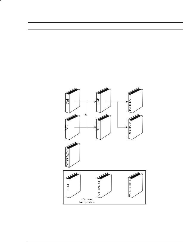
The MindShare Architecture book series includes: ISA System Architecture, EISA System Architecture, 80486 System Architecture, PCI System Architecture, Pentium System Architecture, PCMCIA System Architecture, PowerPC System Architecture, Plug-and-Play System Architecture, and AMD K5 System Architecture.
Rather than duplicating common information in each book, the series uses the building-block approach. ISA System Architecture is the core book upon which the others build. The figure below illustrates the relationship of the books to each other.
Series Organization
1

EISA System Architecture
Organization of This Book
EISA System Architecture is divided into two major parts:
•Part One — The EISA Specification
•Part Two — The Intel 82350DT EISA Chip Set
Part One provides a detailed explanation of the ISA enhancements as set forth in the EISA specification, while Part Two provides a detailed description of the features implemented by the Intel 82350DT chip set. The following paragraphs provide a summary of each section.
Part One – The EISA Specification
EISA Overview
This chapter provides an overview of the benefits provided by the EISA extension to ISA.
EISA Bus Structure Overview
This chapter introduces the EISA bus structure and its relationship to the system board and expansion cards. The concepts of master and slave are introduced and defined. The types of bus masters and slaves are identified.
EISA Bus Arbitration
The bus arbitration scheme used by the EISA Central Arbitration Control is described in detail.
Interrupt Handling
An in-depth discussion of interrupt request handling in the ISA environment can be found in the chapter entitled “Interrupt Handling” in the MindShare book entitled ISA System Architecture. This chapter provides a brief review of the ISA interrupt request handling method and a detailed description of the EISA method.
2
About This Book
Detailed Description of EISA Bus
This chapter provides a description of all the signals on the EISA bus.
ISA Bus Cycles
This chapter provides a review of the ISA bus master and DMA bus cycles.
EISA CPU and Bus Master Bus Cycles
This chapter provides a detailed description of the EISA CPU and bus master bus cycle types.
EISA DMA
This chapter describes the EISA DMA capability. This includes a description of the EISA DMA bus cycle types and the other improved capabilities of the EISA DMA controller.
EISA System Configuration
In this chapter, EISA automatic system configuration is discussed. This includes a description of the slot-specific I/O address space, the EISA product identifier, and the EISA card control ports. The EISA configuration process and board description files are also covered.
Part Two – The Intel 82350DT EISA Chipset
EISA System Buses
This chapter describes the major buses found in virtually all EISA systems. This includes the host, EISA, ISA and X buses.
Bridge, Translator, Pathfinder, Toolbox
This chapter provides a description of the major functions performed by the typical EISA chip set. It acts as the bridge between the host and EISA buses. It translates addresses and other bus cycle information into the form understood by all of the host, EISA and ISA devices in a system. When necessary, it performs data bus steering to ensure data travels over the correct paths between
3

EISA System Architecture
the current bus master and the currently addressed device. It incorporates a toolbox including all of the standard support logic necessary in any EISA machine. It should be noted that the ISA bus is a subset of the EISA bus.
Intel 82350DT EISA Chip Set
This chapter provides an introduction to the Intel 82350DT EISA chip set. The focus is on the 82358DT EISA Bus Controller (EBC) the 82357 Integrated Systems Peripheral (ISP) and the 82352 EISA Bus Buffers (EBBs).
Who This Book Is For
This book is intended for use by hardware and software design and support personnel. Due to the clear, concise explanatory methods used to describe each subject, personnel outside of the design field may also find the text useful.
Those interested only in the compatibility and performance-related issues can skip over the detailed discussions and home in on the issues that interest them. Those interested in a more detailed explanation of the logic behind the enhancements can read the detailed explanations of bus cycle types and the EISA chip set.
Prerequisite Knowledge
EISA stands for the Extension to the Industry Standard Architecture. In order to fully grasp the EISA extensions, it is necessary to first understand the ISA system architecture. The detailed description of EISA presented in this book builds upon the concepts introduced in MindShare's book entitled ISA System Architecture to provide a clear, concise explanation of the EISA environment.
Documentation Conventions
This section defines the typographical conventions used throughout this book.
4

About This Book
Hex Notation
All hex numbers are followed by an “h.” Examples:
9A4Eh
0100h
Binary Notation
All binary numbers are followed by a “b.” Examples:
0001 0101b
01b
Decimal Notation
When required for clarity, decimal numbers are followed by a “d.” Examples:
256d
128d
Signal Name Representation
Each signal that assumes the logic low state when asserted is followed by a pound sign (#). As an example, the REFRESH# signal is asserted low when the refresh logic runs a refresh bus cycle.
Signals that are not followed by a pound sign are asserted when they assume the logic high state. As an example, DREQ3 is asserted high to indicate that the device using DMA Channel three is ready for data to be transfered.
Bit Field Identification (logical bit or signal groups)
All bit fields are designated as follows:
[X:Y],
5

EISA System Architecture
where X is the most-significant bit and Y is the least-significant bit of the field. As an example, the ISA data bus consists of SD[15:0], where SD0 is the leastsignificant and SD15 the most-significant bit of the field.
We Want Your Feedback
MindShare values your comments and suggestions. You can contact us via mail, phone, fax or internet email.
Phone (800) 633-1440
Fax (719) 487-1434
Email tom@mindshare.com
Web Site
Because we are constantly on the road teaching, we can be difficult to get hold of. To help alleviate problems associated with our migratory habits, we have a web site to supply the following services:
•Download course abstracts.
•Download tables of contents of each book in the series.
•Facility to inquire about public architecture seminars.
•Message area to log technical questions.
•Message area to log suggestions for book improvements.
•Facility to view book errata and clarifications.
Web Site: www.mindshare.com
Mailing Address
MindShare, Inc.
4285 Slash Pine Dr.
Colorado Springs, CO 80908
6

PART ONE
THE EISA
SPECIFICATION
