


Chapter 9: EISA System Configuration
Chapter 9
The Previous Chapter
The previous chapter, “EISA DMA,” described the bus cycle types supported by the EISA DMA controller. In addition, other EISA DMA enhancements were also described.
This Chapter
In this chapter, EISA automatic system configuration is discussed. This includes a description of the slot-specific I/O address space, the EISA product identifier, and the EISA card control ports. The EISA configuration process and board description files are also covered.
The Next Chapter
The next chapter begins Part two of the book. In Part two, the Intel EISA chip set and its relationship to the major system components are discussed.
ISA I/O Address Space Problem
When the original IBM PC and XT were designed, IBM defined the use of the processor's 64KB I/O address space as shown in table 9-1.
Table 9-1. IBM PC and XT I/O Address Space Usage
|
I/O Address Range |
|
|
Reserved For |
|
|
|
|
|
|
|
|
0000h – 00FFh |
|
|
256 locations set aside for I/O devices integrated onto the |
|
|
|
|
|
system board. |
|
|
0100h – 03FFh |
|
|
768 locations set aside for I/O expansion cards. |
|
|
0400h – FFFFh |
|
|
Reserved. Do not use. |
|
I/O addresses above 03FFh could not be used due to the inadequate I/O address decode performed by many of the early I/O expansion cards. The card's I/O address decoder inspects A[9:5] to determine which of twenty-four blocks
91
EISA System Architecture
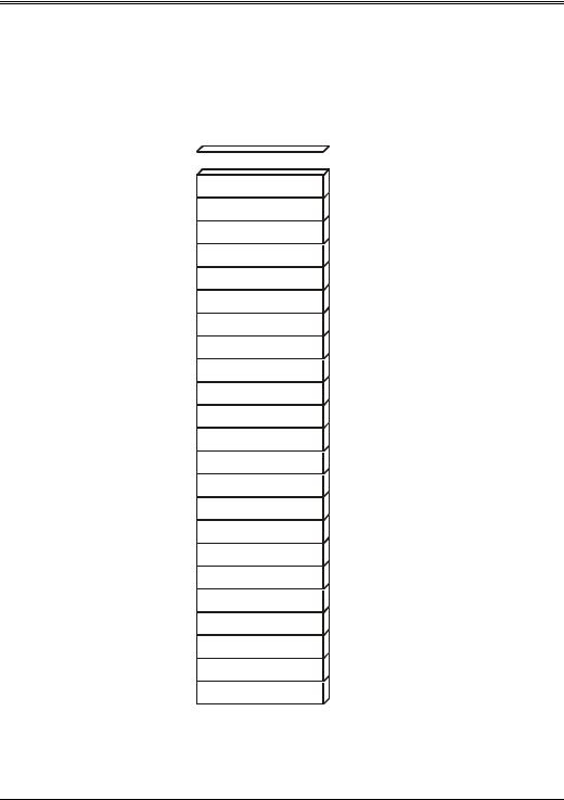
of I/O space is currently being addressed. Each block consists of 32 locations. Figure 9-1 illustrates these twenty-four address ranges. If the currentlyaddressed I/O location is within the block of thirty-two locations assigned to the I/O expansion card, the card's logic examines address bits A[4:0] to determine if one of up to thirty-two I/O ports on the addressed expansion card is being addressed.


 03E0-03FF 03C0-03DF
03A0-03BF
0380-039F
0360-037F
0340-035F
0320-033F
0300-031F
02E0-02FF
02C0-02DF
02A0-02BF
0280-029F
0260-027F
0240-025F
0220-023F
0200-021F
01E0-01FF
01C0-01DF
01A0-01BF
0180-019F
0160-017F
0140-015F
0120-013F
0100-011F
Figure 9-1. ISA Expansion I/O Ranges
92
Chapter 9: EISA System Configuration
The I/O address decoders on the expansion cards for the PC, XT and AT only looked at address bits A[9:5], ignoring bits A[15:10]. The I/O address range assigned for usage by expansion cards is 0100h – 03FFh. Bits A9 and A8 would therefore be either 01b (0100h – 01FFh range), 10b (0200h – 02FFh range), or 11b (0300h – 03FFh range) when an ISA I/O card is being addressed. When the microprocessor places any address within the expansion I/O address range on the address bus, an I/O expansion card may respond.
As an example, assume that a machine has two expansion cards installed. One of them performs an inadequate address decode using just A[9:5] and has eight registers residing at I/O ports 0100h – 0107h. The other card performs a full decode using A[15:5] and has four registers residing at I/O ports 0500h – 0503h. Now assume that the microprocessor initiates a one byte I/O read from I/O port 0500h. The address placed on the bus is shown in table 9-2.
Table 9-2. Example I/O Address
|
A15 |
|
|
A14 |
|
|
A13 |
|
|
A12 |
|
|
A11 |
|
|
A10 |
|
|
A9 |
|
|
A8 |
|
|
A7 |
|
|
A6 |
|
|
A5 |
|
|
A4 |
|
|
A3 |
|
|
A2 |
|
|
A1 |
|
|
A0 |
|
|
|
|
|
|
|
|
|
|
|
|
|
|
|
|
|
|
|
|
|
|
|
|
|
|
|
|
|
|
|
|
|
|
|
|
|
|
|
|
|
|
|
|
|
|
|
|
|
|
0 |
|
0 |
|
0 |
|
0 |
|
0 |
|
1 |
|
0 |
|
1 |
|
0 |
|
0 |
|
0 |
|
0 |
|
0 |
|
0 |
|
0 |
|
0 |
|
|||||||||||||||
The board that occupies the 0500h – 0503h range looks at A[15:5] and determines that the address is within the 0500h – 051Fh block. It then looks at A[4:0] and determines that location 0500h is being addressed. Since this is an I/O read bus cycle, the card places the contents of location 0500h on the lower data path (this is an even address).
At the same time, the board that occupies the 0100h – 0107h range looks at A[9:5], a subset of the address seen by the other card's address decoder, and determines that the address appears to be within the 0100h – 01FFh block. It then looks at A[4:0] and determines that location 0100h is being addressed. Since this is an I/O read bus cycle, the card places the contents of location 0100h on the lower data path (this is an even address).
Since both cards are driving a byte of data onto the lower data path, SD[7:0], data bus contention is occurring. This results in garbage data and possible hardware damage because two separate current sources are driving the lower data path. The problem occurs because the card residing in the 0100h – 0107h range looks at A[9:8] and thinks that this address is within the 0100h – 01FFh range. If the card were designed to perform a full address decode using A[15:5], the problem could have been avoided.
Addresses above 03FFh may be used as long as A[9:8] are always 00b, thus ensuring that the address will not appear to be in the 0100h – 01FFh, 0200h –
93

EISA System Architecture
02FFh, or 0300h – 03FF ranges. Table 9-3 illustrates the usability or unusability of address ranges above 03FFh.
Table 9-3. Usable and Unusable I/O Address Ranges Above 03FFh
|
I/O Address Range |
|
|
Usable or Unusable |
|
|
|
|
|
|
|
|
x000h – x0FFh |
|
|
usable |
|
|
x100h – x1FFh |
|
|
Unusable. Appears to be 0100h – 01FFh |
|
|
x200h – x2FFh |
|
|
Unusable. Appears to be 0200h – 02FFh |
|
|
x300h – x3FFh |
|
|
Unusable. Appears to be 0300h – 03FFh |
|
|
x400h – x4FFh |
|
|
usable |
|
|
x500h – x5FFh |
|
|
Unusable. Appears to be 0100h – 01FFh |
|
|
x600h – x6FFh |
|
|
Unusable. Appears to be 0200h – 02FFh |
|
|
x700h – x7FFh |
|
|
Unusable. Appears to be 0300h – 03FFh |
|
|
x800h – x8FFh |
|
|
usable |
|
|
x900h – x9FFh |
|
|
Unusable. Appears to be 0100h – 01FFh |
|
|
xA00h – xAFFh |
|
|
Unusable. Appears to be 0200h – 02FFh |
|
|
xB00h – xBFFh |
|
|
Unusable. Appears to be 0300h – 03FFh |
|
|
xC00h – xCFFh |
|
|
usable |
|
|
xD00h – xDFFh |
|
|
Unusable. Appears to be 0100h – 01FFh |
|
|
xE00h – xEFFh |
|
|
Unusable. Appears to be 0200h – 02FFh |
|
|
xF00h – xFFFh |
|
|
Unusable. Appears to be 0300h – 03FFh |
|
|
Note: where x = any hex digit |
|
|
|
|
The next section describes how the EISA specification defines the usage of these allowable address ranges above 03FFh.
EISA Slot-Specific I/O Address Space
The EISA specification expands the number of I/O locations available to system and expansion board designers and also implements automatic configuration of both system and expansion boards.
In addition to the 256 I/O locations available for ISA system board I/O devices (from 0000h – 00FFh), the EISA system board has 768 additional I/O locations available for usage by system board I/O devices. Each EISA expansion slot and each embedded EISA device has 1024 locations of slot-specific I/O address space available for use (in addition to the 768 bytes of ISA I/O address space allocated to ISA expansion boards). An embedded device is an EISA I/O device that is integrated onto the motherboard. In all operational respects, it acts
94

Chapter 9: EISA System Configuration
as if it's installed in an EISA expansion slot. Table 9-4 defines the I/O address assignment for the EISA system board and the expansion board slots.
Table 9-4. EISA I/O Address Assignment
|
I/O Address |
|
|
|
|
|
|
|
|
|
Range (hex) |
|
|
Reserved For |
|
|
Range Reserved For |
|
|
|
|
|
|
|
|
|
|
|
|
|
0000 |
– 00FF |
|
|
EISA/ISA system board I/O devices |
|
|
System Board |
|
|
0100 |
– 03FF |
|
|
ISA expansion cards |
|
|
ISA cards |
|
|
0400 |
– 04FF |
|
|
EISA system board I/O |
|
|
System Board |
|
|
0500 |
– 07FF |
|
|
alias of ISA range; do not use |
|
|
|
|
|
0800 |
– 08FF |
|
|
EISA system board I/O |
|
|
System Board |
|
|
0900 – 0BFF |
|
|
alias of ISA range; do not use |
|
|
|
|
|
|
0C00 |
– 0CFF |
|
|
EISA system board I/O |
|
|
System Board |
|
|
0D00 – 0FFF |
|
|
alias of ISA range; do not use |
|
|
|
|
|
|
1000 |
– 10FF |
|
|
Slot 1 I/O |
|
|
EISA slot one |
|
|
1100 |
– 13FF |
|
|
alias of ISA range; do not use |
|
|
|
|
|
1400 |
– 14FF |
|
|
Slot 1 I/O |
|
|
EISA slot one |
|
|
1500 |
– 17FF |
|
|
alias of ISA range; do not use |
|
|
|
|
|
1800 |
– 18FF |
|
|
Slot 1 I/O |
|
|
EISA slot one |
|
|
1900 – 1BFF |
|
|
alias of ISA range; do not use |
|
|
|
|
|
|
1C00 |
– 1CFF |
|
|
Slot 1 I/O |
|
|
EISA slot one |
|
|
1D00 – 1FFF |
|
|
alias of ISA range; do not use |
|
|
|
|
|
|
2000 |
– 20FF |
|
|
Slot 2 I/O |
|
|
EISA slot two |
|
|
2100 |
– 23FF |
|
|
alias of ISA range; do not use |
|
|
|
|
|
2400 |
– 24FF |
|
|
Slot 2 I/O |
|
|
EISA slot two |
|
|
2500 |
– 27FF |
|
|
alias of ISA range; do not use |
|
|
|
|
|
2800 |
– 28FF |
|
|
Slot 2 I/O |
|
|
EISA slot two |
|
|
2900 – 2BFF |
|
|
alias of ISA range; do not use |
|
|
|
|
|
|
2C00 |
– 2CFF |
|
|
Slot 2 I/O |
|
|
EISA slot two |
|
|
2D00 – 2FFF |
|
|
alias of ISA range; do not use |
|
|
|
|
|
|
repeated for |
|
|
|
|
|
|
|
|
|
every X000– |
|
|
|
|
|
|
|
|
|
XFFF range |
|
|
|
|
|
|
|
|
In order to implement the slot-specific I/O address ranges illustrated in table 9-4, the AEN logic on the system board in an ISA system must be modified. Figure 9-2 illustrates the AEN decoder located on the EISA system board.
In an ISA system, the DMAC's AEN output is connected to the AEN pin on all ISA expansion slots in parallel. During non-DMA operation, AEN is low, allowing all memory and I/O devices to decode addresses normally. When the
95

EISA System Architecture
DMA controller, or DMAC, is bus master and is placing a memory address on the bus, it asserts AEN (Address Enable). When I/O cards detect AEN high, the DMAC is placing a memory address on the bus and the I/O cards ignore the address. When a memory card detects AEN asserted, it decodes the address on the bus to determine if the DMAC is addressing it.
In an EISA system, when the DMAC is bus master and is addressing memory, it asserts AEN, causing the system board AEN decoder (see figure 9 - 2) to assert all of its AEN outputs. Each AEN output is connected to the AEN pin on a separate connector. In this way, the AEN decoder emulates AEN operation in an ISA machine. No I/O devices should decode the address.
During non-DMA memory bus cycles, the DMAC’s AEN output is deasserted, causing the system board AEN decoder to set all of its AEN outputs low. This permits all memory cards to decode addresses normally.
During non-DMA I/O bus cycles, M/IO# is low, enabling the system board AEN decoder to use the upper digit of the I/O address, A[15:12], to select which of its AEN outputs to set low. If either A8 or A9 is set to one, however, the I/O address is within the range of 768 locations set aside for ISA expansion I/O devices. The AEN decoder sets all of its AEN outputs low, allowing all of the installed I/O cards to decode the address. When a card's AEN line is sensed low, an EISA I/O device that uses slot-specific I/O address space should examine A8 and A9 to ensure both are zero before decoding A[11:0]. If either bit is high, the bus master is addressing an ISA I/O device and the EISA I/O card should not respond.
If A8 and A9 are both zero during an I/O bus cycle, the bus master is addressing slot-specific I/O address space. In response, the AEN decoder uses A[15:12] to determine which one of its AEN outputs to set low. Only the card in the expansion slot to which the selected AEN line is connected can decode and respond to the I/O address. Upon sensing its AEN line low, the card ensures that A[9:8] are zero before decoding A[11:0]. Table 9-5 defines the action taken by the system board's AEN decoder under each set of circumstances.
96

Chapter 9: EISA System Configuration
Table 9-5. AEN Decoder Action Table
|
DMAC's |
|
|
|
|
|
|
|
|
|
|
|
|
|
|
AEN |
|
|
A9 |
|
|
A8 |
|
|
M/IO# |
|
|
AEN Decoder Action |
|
|
|
|
|
|
|
|
|
|
|
|
|
|
|
|
|
1 |
|
|
na |
|
|
na |
|
|
na |
|
|
The DMAC drives its AEN output high when it is |
|
|
|
|
|
|
|
|
|
|
|
|
|
|
bus master and is placing a memory address on the |
|
|
|
|
|
|
|
|
|
|
|
|
|
|
address bus. The AEN decoder responds by driving |
|
|
|
|
|
|
|
|
|
|
|
|
|
|
all of its AEN outputs high. This prevents I/O de- |
|
|
|
|
|
|
|
|
|
|
|
|
|
|
vices from decoding memory addresses. |
|
|
0 |
|
|
na |
|
|
na |
|
1 |
|
|
A device other than the DMAC is bus master and |
|
|
|
|
|
|
|
|
|
|
|
|
|
|
|
has initiated a memory bus cycle. In response, the |
|
|
|
|
|
|
|
|
|
|
|
|
|
|
AEN decoder sets all of its AEN outputs low. The |
|
|
|
|
|
|
|
|
|
|
|
|
|
|
low on the AEN outputs allows both memory and |
|
|
|
|
|
|
|
|
|
|
|
|
|
|
I/O devices to decode addresses. |
|
|
0 |
|
0 |
|
0 |
|
0 |
|
|
A device other than the DMAC is bus master and |
|
|||
|
|
|
|
|
|
|
|
|
|
|
|
|
has initiated an I/O bus cycle. Since A[9:8] are both |
|
|
|
|
|
|
|
|
|
|
|
|
|
|
zero, the bus master is addressing slot-specific I/O |
|
|
|
|
|
|
|
|
|
|
|
|
|
|
address space. In response, the AEN decoder de- |
|
|
|
|
|
|
|
|
|
|
|
|
|
|
codes the high digit of the address, A[15:12], to de- |
|
|
|
|
|
|
|
|
|
|
|
|
|
|
termine which of its AEN outputs to set low. All of |
|
|
|
|
|
|
|
|
|
|
|
|
|
|
the decoder's other AEN outputs are set high. Only |
|
|
|
|
|
|
|
|
|
|
|
|
|
|
the I/O device in the expansion slot addressed by |
|
|
|
|
|
|
|
|
|
|
|
|
|
|
the high digit of the address can decode the I/O |
|
|
|
|
|
|
|
|
|
|
|
|
|
|
address. |
|
|
0 |
|
0 |
|
1 |
|
0 |
|
|
The bus master is addressing an ISA I/O expansion |
|
|||
|
|
|
|
|
|
|
|
|
|
|
|
|
device that resides within the 0100h – 01FFh range. |
|
|
|
|
|
|
|
|
|
|
|
|
|
|
In response, the AEN decoder sets all of its AEN |
|
|
|
|
|
|
|
|
|
|
|
|
|
|
outputs low. EISA I/O devices that use slot-specific |
|
|
|
|
|
|
|
|
|
|
|
|
|
|
I/O address space should not respond when either |
|
|
|
|
|
|
|
|
|
|
|
|
|
|
A8 or A9 are high. |
|
|
0 |
|
1 |
|
0 |
|
0 |
|
|
The bus master is addressing an ISA I/O expansion |
|
|||
|
|
|
|
|
|
|
|
|
|
|
|
|
device that resides within the 0200h – 02FFh range. |
|
|
|
|
|
|
|
|
|
|
|
|
|
|
In response, the AEN decoder sets all of its AEN |
|
|
|
|
|
|
|
|
|
|
|
|
|
|
outputs low. EISA I/O devices that use slot-specific |
|
|
|
|
|
|
|
|
|
|
|
|
|
|
I/O address space should not respond when either |
|
|
|
|
|
|
|
|
|
|
|
|
|
|
A8 or A9 are high. |
|
|
0 |
|
1 |
|
1 |
|
0 |
|
|
The bus master is addressing an ISA I/O expansion |
|
|||
|
|
|
|
|
|
|
|
|
|
|
|
|
device that resides within the 0300h – 03FFh range. |
|
|
|
|
|
|
|
|
|
|
|
|
|
|
In response, the AEN decoder sets all of its AEN |
|
|
|
|
|
|
|
|
|
|
|
|
|
|
outputs low. EISA I/O devices that use slot-specific |
|
|
|
|
|
|
|
|
|
|
|
|
|
|
I/O address space should not respond when either |
|
|
|
|
|
|
|
|
|
|
|
|
|
|
A8 or A9 are high. |
|
97