

System Clock and
Clock Options
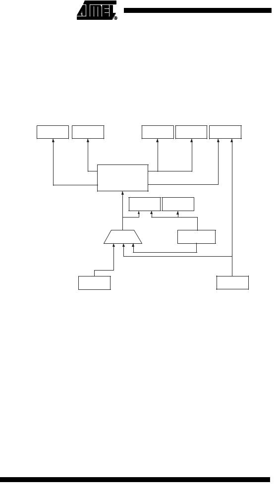
Clock Systems and their Distribution
Figure 11 presents the principal clock systems in the AVR and their distribution. All of the clocks need not be active at a given time. In order to reduce power consumption, the clocks to modules not being used can be halted by using different sleep modes, as described in “Power Management and Sleep Modes” on page 26. The clock systems are detailed below.
Figure 11. |
Clock Distribution |
|
|
|
|
|
|
|
ADC |
General I/O |
|
CPU Core |
RAM |
Flash and |
|
|
Modules |
|
EEPROM |
||||
|
|
|
|
|
|
||
|
|
clkI/O |
AVR Clock |
clkCPU |
|
|
|
|
|
clkADC |
Control Unit |
|
|
|
|
|
|
|
|
|
|
|
|
|
|
|
|
clkFLASH |
|
|
|
|
|
|
Reset Logic |
Watchdog Timer |
|
||
|
|
|
Source clock |
|
|
Watchdog clock |
|
|
|
|
Clock |
|
|
Watchdog |
|
|
|
|
Multiplexer |
|
|
Oscillator |
|
|
|
External Clock |
|
|
|
|
Calibrated RC |
|
|
|
|
|
|
Oscillator |
|
|
|
|
|
|
|
|
|
CPU Clock – clkCPU |
The CPU clock is routed to parts of the system concerned with operation of the AVR |
|
core. Examples of such modules are the General Purpose Register File, the Status Reg- |
|
ister and the Data memory holding the Stack Pointer. Halting the CPU clock inhibits the |
|
core from performing general operations and calculations. |
I/O Clock – clkI/O |
The I/O clock is used by the majority of the I/O modules, like Timer/Counter. The I/O |
|
clock is also used by the External Interrupt module, but note that some external inter- |
|
rupts are detected by asynchronous logic, allowing such interrupts to be detected even if |
|
the I/O clock is halted. |
Flash Clock – clkFLASH |
The Flash clock controls operation of the Flash interface. The Flash clock is usually |
|
active simultaneously with the CPU clock. |
ADC Clock – clkADC |
The ADC is provided with a dedicated clock domain. This allows halting the CPU and |
|
I/O clocks in order to reduce noise generated by digital circuitry. This gives more accu- |
|
rate ADC conversion results. |
20 ATtiny13
2535A–AVR–06/03