


Defining TracePro Solids
You could also choose any two of these four parameters and solve for the other two using these two equations.
To enter this optimal CPC into TracePro, you would set the Front length equal to L, the Back length equal to zero, the Axis tilt equal to θi, and the Lateral focal shift
equal to a. The lateral focal shift is equal to the radius of the exit aperture. See Welford and Winston for further discussion.
If you enter rotation angles, the concentrator is first rotated about the x-axis, then about the y-axis, and finally about the z-axis.
Trough (Cylinder)
A trough or cylinder reflector is a conic section that has been extruded to form a reflector that is uniform in cross-section and generally cylindrical in shape. Trough shapes that can be defined in TracePro are:
•Circular cylinder (an ordinary cylinder)
•Parabolic cylinder
•Elliptical cylinder
•Hyperbolic cylinder
A trough reflector can also have an optional slit along the length, at the vertex of the trough. To include more complex hole structure(s) in this and other reflector types, use the Boolean operations with bounding objects. Note that these Boolean operations will preclude the use of the Modify button on this menu because the object will no longer be seen a Reflector Object.
FIGURE 2.17 - Elliptical Trough with Slit
The parameters necessary to specify a trough reflector are:
•Shape (Circular, Elliptical, Parabolic, or Hyperbolic)
•Length (the length along the cylinder axis)
TracePro 5.0 User’s Manual |
2.19 |
Creating a Solid Model
•Thickness
•Depth (distance from the vertex to the outer edge of the reflector)
•Slit width
•Slit length
•Focal length(s) (or radius for a circular reflector)
•Origin (X, Y, Z coordinates of the vertex)
•Rotation (X, Y, Z rotation angles about the vertex)
Compound Trough
A compound trough reflector is similar to a 3D compound reflector, except that the compound shape is extruded to form a trough instead of being revolved. The discussion for the 3D compound reflectors holds here, except that you must also specify the length of the trough (along the extrusion axis).
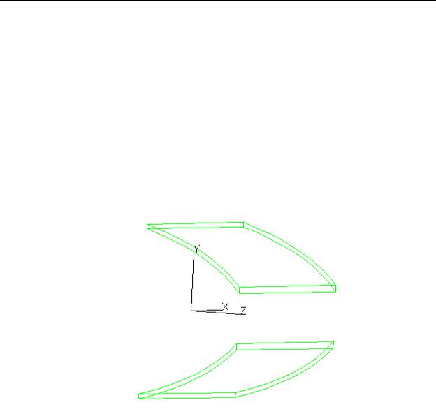
FIGURE 2.18 - Compound Trough Reflector
The parameters necessary to specify a Compound Trough Reflector are:
•Shape (Elliptical or Parabolic)
•Front depth (the distance from the focal points to the entrance port end of the concentrator)
•Back depth (the distance from the focal points to the exit port end of the concentrator)
•Lateral focal shift (equal to the exit port radius for a textbook concentrator)
•Thickness
•Length (along the extrusion axis)
•Axis tilt (equal to the acceptance angle for a textbook concentrator)
•Focal length(s)
2.20 |
TracePro 5.0 User’s Manual |

Defining TracePro Solids
•Origin (X, Y, Z coordinates of the center of the exit port)
•Rotation (X, Y, Z rotation angles about the center of the exit port)
Rectangular Concentrator
A rectangular concentrator is comprised of two Compound Trough reflectors oriented at right angles to one another. This produces a concentrator that is a compound conic in either the x-z or y-z cross section, and is rectangular in any x- y cross section. In the Rectangular Concentrator dialog tab, there are inputs for two compound conics as well as the normal reflector parameters that are needed.
FIGURE 2.19 - Rectangular Concentrator Reflector
The parameters necessary to specify a Rectangular Concentrator Reflector are:
•Shape (Elliptical or Parabolic)
•Front depth (the distance from the focal points to the entrance port end of the concentrator)
•Back depth (the distance from the focal points to the exit port end of the concentrator)
•Lateral focal shifts in X and Y (equal to the exit port radii for a textbook concentrator)
•Thickness
•Axis tilts in X and Y (equal to the acceptance angles for a textbook concentrator)
•Focal length(s) in X and Y
•Origin (X, Y, Z coordinates of the center of the exit port)
•Rotation (X, Y, Z rotation angles about the center of the exit port)
TracePro 5.0 User’s Manual |
2.21 |

Creating a Solid Model
Facetted Rim Ray
Facetted reflectors are often used to produce a uniform irradiance distribution for an extended source. The facets provide smoothing of the reflector’s output by perturbing the imaging qualities of the object. The Facetted Rim Ray in TracePro is an optimized reflector for a given source, package (or enclosure), and irradiance plane. The package is defined by the dimension of the desired object enclosing the reflector.
To specify the reflector, start by locating the package Height, Yp, and Depth Position (Location), Zp, as shown in Figure 2.20. Enter the size of the source,
Source Height, and distance from the vertex of the reflector, Source Location. Next enter the desired output dimensions, Target Height and Location. TracePro will trace a ray from the top of the source to the package position (Yp,Zp), to the
top of the target. The law of reflection will be used to determine the angle of the facet. TracePro will then extend the facet so a ray can be traced from the bottom of the source, to the bottom of the facet, to the bottom of the target. This defines the first facet. Additional facets will be defined until the reflector vertex is crossed. The profile will be revolved in steps based on the #Facets/Row to create the solid reflector.
FIGURE 2.20 - Left: top and bottom rim rays traced for a single facet; Right: package and facet profile
The parameters necessary to specify a Facetted Rim Ray Reflector are:
•Thickness
•# Facets/Row (this is the number of facets created when the profile is sweep about the Z axis, for a circular reflector)
•Length (for a Trough reflector)
•Height (semi height of the package)
•Location (Z distance from the reflector vertex defining the depth of the package)
•Source Height (semi diameter of the source extent along the Y axis)
•Source Location (origin of the source as a Z distance from the reflector vertex)
•Target Height (semi diameter of the target extent along the Y axis)
•Target Location (origin of the target as a Z distance from the reflector vertex)
•Origin (X, Y, Z coordinates of the reflector’s vertex)
•Rotation (X, Y, Z rotation angles about the reflector’s vertex)
2.22 |
TracePro 5.0 User’s Manual |