


RepTile Surfaces
updated RepTile Property Editor appears as shown in Figure 3.49 on page 3.61.
•Once you have selected the File, the Def. Width and Def. Height data entry cells are opened for editing. These are the default tile widths and heights respectively. The initial values are 0, but it is good practice to enter positive spatial dimensions for each. Note that you have the ability to enter model specific values for the Tile width and height (see “Specifying a RepTile Texture File Surface” on page 4.46).
Upon completing the steps listed above, your RepTile Texture File property is complete. There is no additional data that needs to be entered to specify your RepTile Texture File property. Select the Save the Property icon to save the newly created property in the database.
For creation of a Texture File, please See “Texture File Format” on page 7.101 for further discussion on this topic.
FIGURE 3.49 - RepTile Property Editor for the input of a Texture File after the File has been entered or selected and the default width and height have been set.
RepTile Parameterization
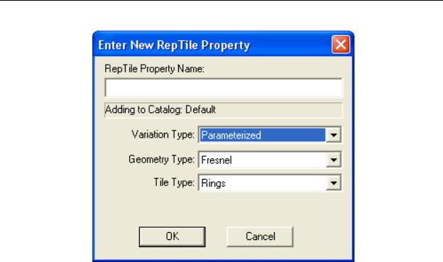
RepTile Geometry and Tile patterns can be parameterized (defined by a mathematical expression). To access this capability, select the Variation Type to be “Parameterized” when creating a new RepTile Property
TracePro 5.0 User’s Manual |
3.61 |
Defining Properties
FIGURE 3.50 - New RepTile Property dialog.
Variables
To add parametrization, variables have been defined based on the types of tile selected for the property. The variables are used to identify a tile’s position within the RepTile geometry. By defining a RepTile parameterization, the tile and geometry can vary over the surface upon which the property is applied. The variables provide in the mathematical expressions vary depending on the Tile Type as follows:
Rectangle and Staggered Rectangle
iRow = row number (counting in the +Y direction) jCol = column number (counting in the +X direction)
Ring
iRing = ring number (counting from the center outward)
jAzi = azimuth angle (in degrees, clockwise from the +x axis)
Parameterized Input Fields
In the RepTile Property Editor, the input fields that appear in Evaluator Control color, see “Background colors” on page 2.53, are fields that will accept a mathematical expression. The expression are the same as the one used in dialog box controls described in the section titled “Expression Evaluator” on page 1.14. The functions can use the variables defined above. The Variables allowed in these expressions are dependent on the Tile Type and Geometry Type as show in Table 3.13 and in Table 3.14.
3.62 |
TracePro 5.0 User’s Manual |
|
|
|
RepTile Surfaces |
|
TABLE 3.13. Tile Parameters |
|
|
|
|
|
|
|
Tile Type |
Input Field |
Associated |
|
|
|
Variable Names |
|
Ring |
Ring Width |
iRing |
|
|
Seg. Width |
IRing, jAzi |
|
|
|
|
|
|
Start Angle |
IRing |
|
|
|
|
|
|
# of Segments |
iRing |
|
|
|
|
|
Rectangles |
Width |
jCol |
|
|
Height |
iRow |
|
|
|
|
|
Staggered Rectangles |
Width |
jCol |
|
|
Height |
iRow |
|
|
|
|
|
|
Row Offset |
iRow |
|
|
|
|
Note that the Row Offset for the Staggered Rectangles tile type is the offset between one row to another. Entering a constant value does not cause any staggering, and, thus, it appears as a Rectangle tile type. To get staggering that varies by row you must enter some functional form with the iRow variable. For example, to obtain a half-tile width stagger, you could use a formula such as:
Row Offset = (TILE WIDTH)*(iRow%2)/2,
where “iRow” indicates the row number, “%2” indicates modulus 2 (i.e., the remainder if you divide iRow by 2), “/2” gives either a value of 0 or 0.5, and “TILE WIDTH” is the value that you entered for the TILE WIDTH (i.e., you must enter the explicit value). The Row Offset value is then the offset in millimeters from one row to another as per the entered equation.
TracePro 5.0 User’s Manual |
3.63 |

Defining Properties
TABLE 3.14. Geometry Parameters
Geometry Type |
Input Field |
Variables allowed |
Fresnel |
Facet Angle |
iRing |
|
Draft Angle |
iRing |
|
|
|
Cone |
End Radius |
iRow / iRing, jCol / jAzi |
|
Depth/Height |
iRow / iRing, jCol / jAzi |
|
|
|
|
Cone Angle |
iRow / iRing, jCol / jAzi |
|
|
|
|
Chamfer Height |
iRow / iRing, jCol / jAzi |
|
|
|
|
Chamfer Angle |
iRow / iRing, jCol / jAzi |
|
|
|
|
Decenter (x, y) |
iRow, jCol |
|
|
|
|
Decenter (r, phi) |
iRing, jAzi |
|
|
|
Sphere |
Radius |
iRow / iRing, jCol / jAzi |
|
Depth/Height |
iRow / iRing, jCol / jAzi |
|
|
|
|
Decenter (x, y) |
iRow, jCol |
|
|
|
|
Decenter (r, phi) |
iRing, jAzi |
|
|
|
Ellipsoid |
X Radius, Y Radius, |
iRow / iRing, jCol / jAzi |
|
Z Radius |
|
|
Center Height |
iRow / iRing, jCol / jAzi |
|
|
|
|
Rotate X, Rotate Y, |
iRow / iRing, jCol / jAzi |
|
Rotate Z |
|
|
Decenter (x, y) |
iRow, jCol |
|
|
|
|
Decenter (r, phi) |
iRing, jAzi |
|
|
|
Hip (Mansard) Roof |
Depth/Width |
iRow / iRing, jCol / jAzi |
|
X Width, Y Width |
iRow / iRing, jCol / jAzi |
|
|
|
|
X Angle, Y Angle |
iRow / iRing, jCol / jAzi |
|
|
|
|
Orient |
iRow / iRing, jCol / jAzi |
|
|
|
|
Decenter (x, y) |
iRow, jCol |
|
|
|
|
Decenter (r, phi) |
iRing, jAzi |
|
|
|
Cube Corner |
(none) |
(none) |
Prism |
Y(0) Angle, Y(1) Angle |
iRow / iRing, jCol / jAzi |
|
X(0) Angle, X(1) Angle |
iRow / iRing, jCol / jAzi |
|
|
|
Rounded Prism |
Y(0) Angle, Y(1) Angle |
iRow / iRing, jCol / jAzi |
|
Peak Radius |
iRow / iRing, jCol / jAzi |
|
|
|
|
Trough Radius |
iRow / iRing, jCol / jAzi |
|
|
|
3.64 |
TracePro 5.0 User’s Manual |