


Defining Properties
Specifying a RepTile surface
The process of making a RepTile surface in TracePro is analogous to applying a surface property. TracePro has a database of basic RepTile surface shapes and geometries, and you can define additional RepTile parameters by adding them to the database. The database is accessed through the RepTile Property Editor. Different tile shapes (ring, segmented ring, rectangular, staggered rectangular, and hexagonal) and tile geometries (conical, spherical, hip-roof, cube-corner, prism, rounded prism, and Fresnel lens) are available. These tile shapes and geometries are explained in the following sections. In general, the geometries can be defined as either “bumps” or “holes”.
Once a RepTile property is entered in the database, it can be applied to a plane surface using the RepTile tab of the Apply Properties dialog box. Additionally, applying a RepTile requires boundary data for the plane surface within which the tiles are to exist and the location of a key reference tile (0,0).
When you apply a RepTile surface to a plane surface, TracePro defines a cell containing the tiled space. The cell has the shape of the boundary (circular, rectangular or hexagonal) and a depth. You must be aware of the depth calculation because the cell must be completely contained within the object that owns the RepTile surface. If this rule is violated, incorrect rays result.
The orientation of tiles in a RepTile surface is specified by the Up Vector. It defines the local y axis of the surface, the plane normal vector defines the local z axis, and the local x axis is orthogonal to the y and z axes and forms a righthanded coordinate system. The width of tile shapes and geometry is the dimension along the local x axis and the height is along the local y axis (the Up Vector). Depth/height of holes/bumps is along the local z axis.
Height
Z
X |
|
Hole |
“Bump” |
|
|||
|
|
Depth
FIGURE 3.29 - Orientation of dimensions along the z-axis.
RepTile Shapes
The tile shapes in a RepTile surface can be one of the following:
• Ring
3.46 |
TracePro 5.0 User’s Manual |

RepTile Surfaces
•Segmented Ring (Parameterized Ring tile)
•Rectangular
•Staggered Rectangular
•Hexagonal
Ring tiles
Ring tiles are simply concentric rings defined by their width. The central ring tile is a circle of radius r0. Ring tiles are used for specifying Fresnel lenses. The location
of the (0,0) tile is the center of the rings.
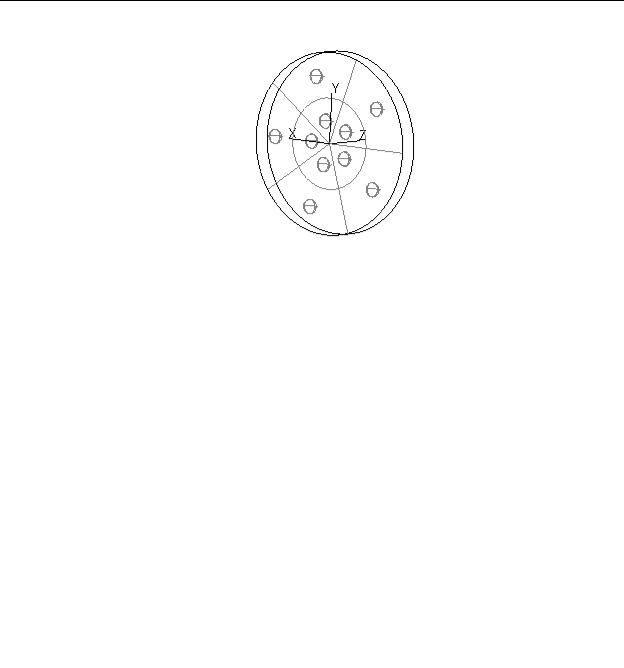
FIGURE 3.30 - Example of ring tiles geometry.
Segmented Ring tiles
Segmented Ring tiles are defined by a radial ring width, an angular segment width, a starting angle and the number of angular segments per ring. The segment width and number of segments are independent parameters. If the segment angular width multiplied by the number of segments is less than 360 degrees, then TracePro will create a final tile to complete the full 360 degrees. This final tile will have no Reptile geometry. If the segment angular width multiplied by the number of segments is greater than 360 degrees, then TracePro will truncate the tiles and thus the geometry at 360 degrees. Figure 3.31 shows an example of segmented ring tiles.
See “RepTile Parameterization” on page 3.61 for further discussion on this topic.
TracePro 5.0 User’s Manual |
3.47 |
Defining Properties
FIGURE 3.31 - Example of segmented ring tiles with spherical hole geometry.
Rectangular tiles
Rectangular tiles are rectangular in shape and are laid out in a rectangular array. Figure 3.32 shows an array of rectangular tiles with conical "bump" geometry. Rectangular tiles are specified by their height and width.
See “RepTile Parameterization” on page 3.61 for further discussion on this topic.
FIGURE 3.32 - Example of rectangular tiles with conical "bump" geometry.
Staggered rectangular tiles
Staggered rectangular tiles are similar to rectangular tiles except that alternate rows of tiles are displaced by one-half the tile width, like brickwork. An example of staggered rectangular tiles with conical "bump" geometry is shown in Figure 3.33. You specify staggered rectangular tiles by their height and width. Note that for Constant (C) or Variable Rows (V) variation types, succeeding rows are staggered by half the tile width. For Parameterized (P) variation type, you must enter the stagger value with the use of the iRow variable in the Row Offset data entry point. Failure to do so, results in a non-staggered array of rectangles. This Row Offset value allows you to vary the stagger as a function of row number, in
3.48 |
TracePro 5.0 User’s Manual |

RepTile Surfaces
fact, it can be nonlinear dependent on the function that you enter for the Row Offset.
See “RepTile Parameterization” on page 3.61 for further discussion on this topic.
FIGURE 3.33 - Example of staggered rectangular tiles with conical "bump" geometry.
Hexagonal tiles
Hexagonal tiles are packed hexagons, like a honeycomb. The width of a hexagon is the distance from one flat side to another and lies along the local x-axis as shown in Figure 3.34. The hexagons are packed with points along the vertical direction defined by the local y-axis or up vector as shown in Figure 3.34.
y
 x
x
width
FIGURE 3.34 - Hexagonal tile with local x and y axes and width parameter
TracePro 5.0 User’s Manual |
3.49 |