

WriteReadOnlyBit
This command allows the user to write the status of the read only bit, which is usd to protect the contents of the smartcard.
![]()
Arguments
Data%
The read-only bit.
|
Value |
Meaning |
|
1 |
Read-only |
|
not 1 |
Read-write |
Return Values
Status%
The status of the operation.
|
Value |
Meaning |
|
0 |
OK |
|
3 |
Communications Failure with the smartcard. |
Example
See SmartCard Example Program for example program.
Target/ Language Restrictions
Only available on SM-Applications and SM-Applications Lite.
See Also
OpenReadSmartCard
OpenWriteSmartCard
CloseSmartCard
ReadSmartCardByte
WriteSmartCardByte
GetNextSmartCardFile
ReadReadOnlyBit
________________________________________________________________________________
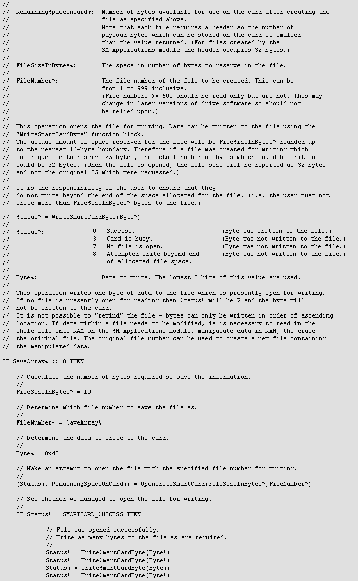
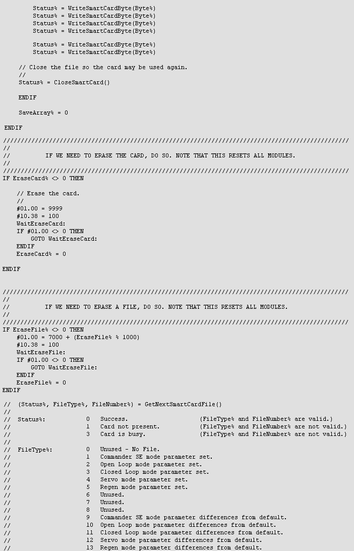
WriteSmartCardByte
This function writes a byte of data to the smartcard. A file must be opened for writing prior to using this command.
![]()
Arguments
Data%
Data byte to write to the SmartCard.
Return Values
Status%
The status of the operation.
|
Value |
Meaning |
|
0 |
OK |
|
3 |
Communications Failure with the smartcard. |
Example
See SmartCard Example Program for example program.
Target/ Language Restrictions
Only available on SM-Applications and SM-Applications Lite.
See Also
OpenReadSmartCard
OpenWriteSmartCard
CloseSmartCard
ReadSmartCardByte
GetNextSmartCardFile
ReadReadOnlyBit
WriteReadOnlyBit
________________________________________________________________________________
Xor4 - Four-input xor Gate
This function returns the result of XORing (exclusive OR) its four inputs.
![]()
Arguments
IN1% to IN3%
The values to be XORed together. Only the bottom bit (bit 0) of each input will be XORed. All other bits in the input will be ignored.
Example

Target/ Language Restrictions
None.
See Also
AND4
NAND4
NOR4
OR4
SmartCard Example Program
The following is an example program using the SmartCard function blocks.
Example


See Also
OpenReadSmartCard
OpenWriteSmartCard
CloseSmartCard
ReadSmartCardByte
WriteSmartCardByte
GetNextSmartCardFile
ReadReadOnlyBit
WriteReadOnlyBit
________________________________________________________________________________
Reference
The language reference provides detailed information assisting in the development of DPL programs:
Supported Languages
Variables, Parameters, Constants and Data Types
Program Structure
DPL (Drive Programming Language) Reference
LD (Ladder) and FBD (Function Block Diagram) Reference
QLD (Quick Ladder Diagram) Reference
Advanced Position Controller
Programming Hints and Tips
Functions & Function Blocks
|
Note: |
This section is the reference for programs developed within the DPL editor (and its diagram editors) in SYPT. The SYPTLite help file contains a reference section for programs developed in SYPTLite. The SYPTLite help file is accessible from the Help menu in SYPTLite. |
________________________________________________________________________________
Supported Languages
SYPT supports the development of user programs in four languages - DPL, QLD, LD and FB. A program can be developed in a mixture of the supported languages. The user is free to mix DPL, QLD and LD/ FB within a program and even within a single function block, subroutine or task definition. For more information on the languages see below.
Drive Programming Language (DPL)
Quick Ladder (QLD)
Full Ladder (LD)
Function Block (FB)
Drive Programming Language (DPL)
This is the main language within SYPT. DPL is high-level, structured language which includes a number of features optimised for use with Control Techniques drives. DPL is suitable for writing any sort of program and includes features common to all high-level computer languages.
It is not possible to write a program in SYPT without using some DPL since all common elements (tasks, variables, aliases) are defined in DPL form. For example, if a Background task is written which includes a function block diagram, the task wrapper and variables used in the diagram are written in DPL.

The diagram shows a Background task in the DPL editor. The task executes in a continuous loop. The task contains a function block diagram which assigns the current time to a variable (MyVar%) and then assigns MyVar% to a parameter (#20.30) on the drive. Even though the main "executable" code is written in a function block diagram, the task structure, variable and parameter are all in DPL form. If the above task were written in DPL alone it would look like the following.

DPL (Drive Programming Language) Reference
Quick Ladder (QLD)
Quick Ladder is a restricted form of ladder programming suited to logic control. The Quick Ladder diagram editor (within the DPL editor) enforces a rigid layout of ladder elements such as contacts, coils and function block calls. Quick Ladder allows a valid ladder diagram to be developed very quickly.
The Quick Ladder editor in SYPT is very similar to the Quick Ladder editor provided in SYPTLite. However, in SYPT the Quick Ladder editor allows the use of user-defined data variables as well as drive parameters.

For more information on QLD, see:
QLD (Quick Ladder Diagram) Reference
Full Ladder (LD)
Full ladder allows more flexibility than QLD, e.g. contacts and coils can be directly connected to function block inputs and outputs. LD diagrams are edited using the same editor (LD/ FBD) as function block diagrams.
 \
\
For more information on LD, see:
LD (Ladder) and FBD (Function Block Diagram) Reference
Function Block (FB)
Function Block provides a good way of visualising flow of data between variables and functions or function blocks. Function Block diagrams provide an intuitive way of expressing a program. Function block diagrams are edited using the same editor (LD/ FBD) as LD diagrams.

For more information on FB, see:
LD (Ladder) and FBD (Function Block Diagram) Reference
See Also
Reference
________________________________________________________________________________