

- •Introduction
- •1 Quick Start
- •Overview of the Example
- •Create a Project and Adding a Drive
- •Editing the Program
- •Building and Downloading the Program
- •Monitoring Operation of the Program
- •Importing sm-Applications Lite syptLite Programs
- •Upgrading from the dpl Toolkit
- •Loading a dpl File from disk
- •Uploading a dpl File from a Target Node
- •Starting sypt
- •Configuration Editor
- •Menu Bar
- •Toolbars
- •View toolbar for the Hardware Architecture view
- •Status Bar
- •Hardware Architecture View
- •Link Architecture View
- •Cyclic Data View
- •Specifying Workbench Options
- •Dpl Editor
- •SyptLite
- •Watch Window
- •Menu Bar
- •Managing Projects
- •Creating Projects
- •Opening Projects
- •Saving Projects
- •Viewing Project Properties
- •Cloning Projects
- •Closing Projects
- •Printing Projects
- •Defining a Project Header
- •Inserting Nodes
- •Selecting Nodes
- •Editing the Properties of Nodes
- •Editing Node Descriptions
- •Deleting Nodes
- •Cutting, Copying, and Pasting Nodes
- •Rearranging Nodes
- •Networks
- •Unreachable Nodes
- •Inserting Networks
- •Selecting Networks
- •Deleting Networks
- •Editing the Properties of Networks
- •Pc Communications Settings
- •Rearranging Networks
- •Splitting Network Rails
- •Merging Network Rails
- •Cyclic Data Links
- •Inserting Data Links
- •Inserting Broadcast Links
- •Defining Cyclic Data
- •Viewing Cyclic Data
- •Selecting Links
- •Rearranging Links
- •Deleting Data Links
- •Editing Source/Destination Node Descriptions
- •Annotations
- •Inserting Annotations
- •Editing the Contents of Annotations
- •Formatting Text in Annotations
- •Deleting Annotations
- •Dpl Programs
- •Creating Programs
- •Opening and Closing Programs
- •Saving Programs
- •Editing Programs
- •Specifying the Floating-Point Model
- •Inserting Sections
- •Inserting Diagrams
- •Inserting Variables, Parameters or Numbers
- •Inserting Function Block Calls
- •Inserting Files
- •Inserting the Date and Time
- •Selecting Items in Programs
- •Cutting, Copying, and Pasting Items
- •Finding and Replacing Text
- •Go to a Source Line
- •Editing Diagram Titles
- •Editing/ Viewing the Properties of Programs
- •Printing Programs
- •Templates
- •Dpl Syntax Templates
- •Defining a Template
- •Dpl Templates Dialog
- •Defining a Template Category
- •Deleting a Template/ Changing a Template Name
- •Deleting a Category/ Changing a Category Name
- •Template Shortcut keys
- •Inserting a Template into a Program
- •Creating a Library
- •Specifying Function Block Properties
- •Library Folder Structure
- •Viewing Library Properties
- •Library Manager
- •Referencing and Using a Library
- •Removing a Reference To a Library
- •Exporting a Library
- •Importing a Library
- •Switching the Configuration Editor Online
- •Switching the Configuration Editor Offline
- •Node Detection and Indications
- •Successfully Detected Nodes
- •New Node
- •Nodes Not Found
- •Cyclic Data Mismatches
- •Cyclic Master and Trip Indications
- •Refreshing the View of Nodes While Online
- •Adding Detected Nodes
- •Deleting Target User Programs
- •Building Applications
- •Showing Build Errors
- •Downloading Node Programs
- •Uploading Node Programs
- •_______________________________________________________________________________________________ Accessing Diagnostic Information for Nodes
- •Accessing Identification Information for Nodes
- •Monitoring the Values of Variables and Parameters
- •Watching Values in the dpl Editor
- •Setting Up a Watch List
- •Opening and Closing Watch Lists
- •Saving Watch Lists
- •Adding Variables and Parameters to a Watch List
- •Selecting Watch List Items
- •Cutting, Copying, and Pasting Watch List Items
- •Removing Items from a Watch List
- •Editing the Properties of Watch List Items
- •Rearranging the Order of Watch List Items
- •Changing the Values of Variables or Parameters
- •Controlling Program Execution
- •Stopping and Starting Programs
- •Pausing and Resuming Programs
- •Stopping and Stepping Tasks
- •Running Tasks
- •Using Breakpoints
- •Switching dpl Programs to Editing Mode
- •Resetting Node Programs
- •Resetting Drives
- •Abs - Absolute
- •Ansiread - ansi Master Command
- •Ansireadn - ansi Master Command
- •Ansireply - ansi Master Command (ud70 and md29)
- •Ansireply - ansi Master Command (sm-Applications)
- •Ansiwrite - ansi Master Command
- •Ansiwriten - ansi Master Command
- •ApcSetRunMode
- •ApcReset
- •ApcGetOutputSpeed
- •ApcGetOutputSpeedRpmx10
- •ApcSelectAbsoluteMode
- •ApcSelectRelativeMode
- •ApcReadPar
- •ApcSetPositionResetOffset
- •ApcResetSourcesOnDisable
- •ApcDoNotResetSourcesOnDisable
- •ApcSetReferenceSource
- •ApcSetFeedbackSource
- •ApcSetNumOfTurnsBits
- •ApcEnableRefSourceMarker
- •ApcDisableRefSourceMarker
- •ApcEnableFbckSourceMarker
- •ApcDisableFbckSourceMarker
- •ApcResetRefSourceMarkerFlag
- •ApcResetFbckSourceMarkerFlag
- •ApcResetRefSourceFreezeFlag
- •ApcResetFbckSourceFreezeFlag
- •ApcInvertRefSource
- •ApcDoNotInvertRefSource
- •ApcInvertFbckSource
- •ApcDoNotInvertFbckSource
- •ApcSetReferencePosition
- •ApcSetFeedbackPosition
- •ApcGetReferenceStatus
- •ApcGetFeedbackStatus
- •ApcSelectReference
- •ApcSelectActionOnFreeze
- •ApcSetStopMode
- •ApcSetPositionSetPoint
- •ApcSetSpeedSetPoint
- •ApccamInitialise
- •ApccamInitialise1
- •ApccamInitialise2
- •ApccamInitialise3
- •ApcSetCamStartIndex
- •ApcSetCamSize
- •ApcSetCamDeltaSegLimit
- •ApcSetCamInterpolationMode
- •ApcSetCamOutRatioNumerator
- •ApcSetCamOutRatioDenominator
- •ApcSelectCamAbsoluteReset
- •ApcSelectCamZeroReset
- •ApcSetCamAbsResetIndex
- •ApcSetCamAbsResetPositionInSeg
- •ApcEnableCamSingleShot
- •ApcDisableCamSingleShot
- •ApcSetDigLockMode
- •ApcSetDigLockRatioNumerator
- •ApcSetDigLockRatioDenominator
- •ApcSetDigLockLockingSpeed
- •ApcSetDigLockLockingPosition
- •ApcSetSpeedOffset
- •ApcSetPositionOffset
- •ApcDisableRigidLock
- •ApcEnableProfile
- •ApcDisableProfile
- •ApcSetProfileAccelRate
- •ApcSetProfileDecelRate
- •ApcSetProfileMaxSpeedClamp
- •ApcSetPGain
- •ApcSetPGainSpeedClamp
- •ApcEnableExternalRefSpeed
- •ApcDisableExternalRefSpeed
- •ApcSetExternalRefSpeed
- •ApcEnableExternalRefPosition
- •ApcDisableExternalRefPosition
- •ApcSetExternalRefPosition
- •ApcSetOutputRatioNumerator
- •ApcSetOutputRatioDenominator
- •ApcSetupOutputChannel
- •ApcEnableOutputChannel
- •ApcDisableOutputChannel
- •ApcWriteOutputChannel
- •ApcToUserPosition
- •ApcToUserVelocity
- •ApcToUserAcceleration
- •Arrayget - Get Array Element
- •Arrayset - Set array element
- •Arraysort
- •Arraystat
- •Assram - Associate an array with a file
- •Autosync - ctNet Sync Master Redundancy
- •Autosyncerror
- •Average - Running Average
- •Bcd2bin - Binary-coded Decimal to Binary Conversion
- •Bin2bcd - Binary to Binary-coded Decimal Conversion
- •Bcd2seg - Binary-coded Decimal to Seven-segment Display Data
- •Blkdef - Block Parameter Write
- •Bridge - rs485 Serial Protocol Function
- •Cambox - cam function generator
- •Cambox2 - cam function generator
- •Cambox/cambox2 - cam information
- •Caminit - cam Table Initialise
- •CanConfigEvent
- •CanGetNodeAddr
- •CanReady
- •CanSetup
- •CanStatus
- •CanStatusAll
- •Checknode - Check Existence of Node on ctNet
- •CloseSmartCard
- •Cmodexfer
- •Cmp - Comparison Block
- •Condparw - Conditional Parameter Write
- •ConvertBackwards
- •ConvertForwards
- •Cos - Cosine Function
- •Crc16 - Cyclic Redundancy Check
- •Ctd - Down Counter
- •Ctu - Up Counter
- •Ctud - Up/ Down Counter
- •Ctnetdiagnostics
- •CtSyncDisableOutputChannel
- •CtSyncEnableOutputChannel
- •CtSyncGetSlaveReferences
- •CtSyncSetMasterReferences
- •CtSyncSetupOutputChannel
- •CtSyncWriteOutputChannel
- •Datastuff
- •Decoder4/decoder8
- •Digsel8 - Digital Select Block
- •IDMux/ fDMux / iDMux8 - De-multiplexers
- •Dterm - Differentiator Block
- •Editfastlink/editslowlink - ctNet Cyclic Link Editing
- •Egb / egb2
- •EnableCanTrips
- •Encoder4/encoder8 - Binary Encoder Blocks
- •Exp - Exponential Function
- •Filter - First-order Digital Filter
- •Float - Integer to Floating Point Conversion
- •Float32
- •Getchar - Read rs485 Port
- •GetNextSmartCardFile
- •GetParAttr
- •GetSamplesPerSec
- •GetTaskId
- •Home1 - Homing function
- •Home2 - Homing function
- •HiLoDet - Max and min value detection
- •Int - Floating Point to Integer Conversion
- •ITerm - Integrator Block
- •IWindow
- •ILimit/ fLimit
- •ILimit2/ fLimit2
- •IInvert/fInvert
- •Ln - Natural Logarithm
- •LinInt - Linear Interpolation
- •Modexfer
- •Mpot - Motorised Pot
- •Muldivrm
- •IMux / fMux / iMux2 / fMux2 / iMux8 - Multiplexers
- •Nand4 - Four-input nand Gate
- •Neg - Inverts Input
- •Netreply
- •Netstatus
- •Nor4 - Four-input nor Gate
- •OpenReadSmartCard
- •OpenWriteSmartCard
- •Or4 - Four-input or Gate
- •IOs/ fOs - Offset-Scale
- •Pfixread - Fixed Precision (3 dps) Parameter Read
- •Pfixread6 - Fixed Precision (6 dps) Parameter Read
- •Pfixwrite - Fixed Precision (3 dps) Parameter Write
- •Pfixwrite6 - Fixed Precision (6 dps) Parameter Write
- •Pid - pid Block
- •Posloop - Position Loop Controller
- •Posloop2 - Position Loop Controller
- •Precisiontimer
- •Pt - Pulse Timer
- •Ptd - Pulse Timer
- •Putblock
- •PutBottomWord
- •Putchar - Write Character to rs485 Port
- •Putkey - Write Character to Port
- •PutTopWord
- •RamLength
- •Ramp - Linear Ramp
- •Readnet
- •Readnetb
- •ReadReadOnlyBit
- •ReadSmartCardByte
- •Reg - Registration Block
- •ResetCanTimer
- •Rs/sr : Event Memory Latches
- •RtuReadRegs
- •RtuReadParas
- •RtuReadInputRegs
- •RtuPresetRegs
- •RtuPresetParas
- •RtuMasterReply
- •RtuMasterStatus
- •Runtime
- •Scheduleevent
- •SetConverterDenominator
- •SetConverterNumerator
- •SetCtnSync
- •SetRamLength
- •SetUserId
- •Shiftlr
- •SignedBottomWord
- •SignedTopWord
- •Sin - Sine Function
- •ISo/fSo : Scale-Offset
- •Splitter
- •SpGateway - ctNet to fieldbus gateway
- •Sq1int/ Sq2int - Square Interpolation
- •Sqr - Square Root Function
- •Sramp - s-Ramp Profile Generator Function
- •Ssramp - s-Ramp Profile Generator Function
- •Stuff2 / stuff4 / stuff8 - Bit Stuffers
- •Tan - Tan Function
- •Tcyclic - Cyclic Timer
- •ToffRet
- •Trl - Triggered Latch Function
- •UnAssram
- •UnsignedBottomWord
- •UnsignedTopWord
- •UserToApcAcceleration
- •UserToApcPosition
- •UserToApcVelocity
- •Vel2pos - Velocity Profile Integrator
- •Writenet
- •Writenetb
- •Wrnet - ctNet Write Command
- •Wrnetb - ctNet Block Parameter Write Command
- •WriteReadOnlyBit
- •WriteSmartCardByte
- •Xor4 - Four-input xor Gate
- •SmartCard Example Program
- •Supported Languages
- •Variables, Parameters, Constants and Data Types
- •Variables
- •Bit Access For Variables
- •Predefined Variables
- •Parameters
- •Plc Registers
- •Data Types
- •Constants
- •Numbers
- •Variable and Parameter Scope
- •Aliases
- •Program Structure
- •Subroutines
- •User-Defined Function Blocks (udfBs)
- •Calling udfBs
- •Udfb Argument Restrictions
- •Udfb Instances
- •Udfb Code Sections
- •Dpl (Drive Programming Language) Reference
- •Directives
- •Operators
- •Conditional Operators
- •Comments
- •Constructs
- •Variable Assignment
- •If ... Then
- •For Loop
- •Function Block Call
- •Ld/ fb Elements
- •Ld/ fb Coil Types
- •Ld/ fb Contact Types
- •Ld/ fb Order of Execution
- •Qld (Quick Ladder Diagram) Reference
- •Qld Elements
- •Qld Coil Types
- •Qld Contact Types
- •Advanced Position Controller
- •Programming Hints and Tips
- •Copyright
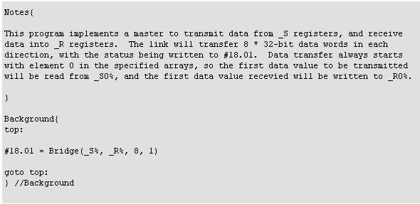
Bridge - rs485 Serial Protocol Function
Uses the RS485 port on MD29 or UD70 to implement a high speed protocol bridge function. Point-to-point only, one side must be configured as master, one side as slave. Due to the internal protocol, Bridge must use an RS485 communcations mode. with 9 data bits, and the data rate must be the same in both nodes. If an incorrect mode is selected, an error will be indicated..
![]()
NOTE: UD70 Issue 5 hardware is required to run at 250kbps and 500kbps in Mode 12.
Bridge can be used for any application that needs to transfer a large amount of data between two UD70 or MD29 nodes. 2 examples are:
1. Protocol bridge. This block can be used to transfer data from a Unidrive/ Profibus-DP interface to a Unidrive or Mentor II CTNet interface. This allows a large amount of data to be transferred between 2 networks.
2. Array transfer. If there is a need to transfer a large array between 2 nodes, e.g. for a CAM table, Bridge could be used.
The wiring connections required to implement link are given in the table below.

Arguments
TxDat%
Specifies the integer data array containing the data values to be transmitted.
RxDat%
Specifies the integer data array into which received values will be written.
Regs%

Example
The following example shows a program to be used on a master node and a program to be used on a slave node in order to create a communications bridge.

Target/ Language Restrictions
Bridge can only be used on a UD7X or MD29 (Mentor II).
________________________________________________________________________________
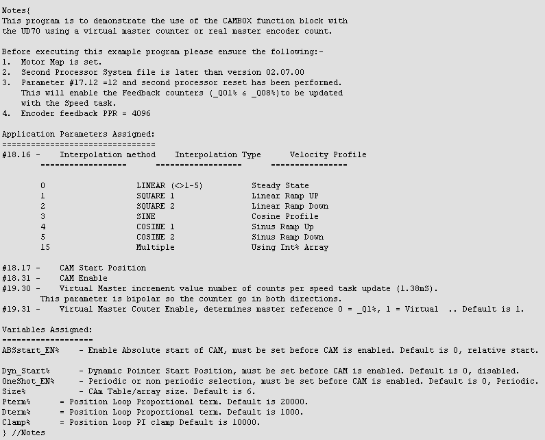
Cambox - cam function generator
This function provides a versatile CAM function generator..
![]()
Arguments
EN%
Enable. 0 disables the CAMBOX, 1 enables.
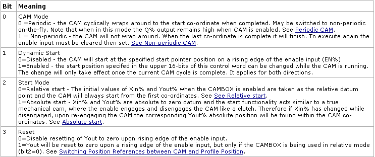
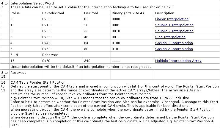
Ctrl%
Bitmapped Control word.
X%
The X (master) axis array. The array can be constant (CONST) or variable. See CAM Tables information.
Y%
The Y (slave) axis array. The array can be either constant (CONST) or variable. See CAM Tables information.
fx%
Interpolation array, when using multiple interpolation. The array can be either constant (CONST) or variable. See CAM Tables information
Size%
This determines the size of the array and is used in conjunction with bit 1 of the Control Word and the Pointer start position. See CAM Tables information
Xin%
The X (master) axis reference to the CAMBOX.
Return Values
Q%
Periodic mode - Set high once CAMBOX is enabled.
Single shot mode - Set high once the CAM profile is complete. Cleared (set to zero) when the Reset bit is cleared.
Ptr%
The current position of the pointer within the CAM table.
Error%
Decimal value of the internal CAMBOX error.
|
Value |
Meaning |
|
0 |
Healthy |
|
1 |
Array length defined by start pointer position and size is out of bounds of the dimensioned array. |
|
2 |
The limit of 250 iterations of the CAMBOX has been exceeded due to the master (Xin%) axis increment/decrement delta value being too large to calculate. |
Yout%
The interpolated output from the CAM generator, which is based on the value of Xin (master) with respect to the CAM tables and the type of interpolation used.


See Also
CAMBOX2
POSLOOP
________________________________________________________________________________