

Cambox2 - cam function generator
This function provides a versatile CAM function generator.
![]()
Arguments
Ctrl%[0]
Bitmapped of Control word.

Ctrl%[1]
Array size. Determines the size of the array and is used in conjunction with dynamic start (Ctrl%[0], bit2) and the pointer start position (Ctrl%[0], bits 16-31).
Ctrl%[2]
Xin. The X (master) axis reference to the CAMBOX2.
X%
The X (master) axis array. The array can be constant (CONST) or variable. See CAM Tables information.
Y1%
The Y (slave1) axis array. The array can be either constant (CONST) or variable. See CAM Tables information.
fx%
Interpolation array, when using multiple interpolation. It specifies the interpolation technique to use with respect to the Master and Slave (X% and Y1%) co-ordinate. The array can be either constant (CONST) or variable. See CAM Tables information.
Y2%
The Y2 (slave2) axis array. The array can be either constant (CONST) or variable. The output of this array is summed with the Y1 slave array. When this is defined linear interpolation is used between each co-ordinate with reference to the Master axis (X%). See CAM Tables information.
Return Values
Q%
Periodic mode - Set high once CAMBOX2 is enabled.
Single shot mode - Set high once the CAM profile is complete. Cleared (set to zero) when the Reset bit is cleared.
Ptr%
The current position of the pointer within the CAM table.
Error%
Decimal value of the internal CAMBOX2 error.

Yout%
The interpolated output from the CAM generator, which is based on the value of master (Ctrl%[2]) reference with respect to the CAM tables and the type of interpolation used.
Combined Profiles using Slave1 and Slave2 Profiles

See Also
CAMBOX
POSLOOP
________________________________________________________________________________
Cambox/cambox2 - cam information
CAMBOX
CAMBOX2
Linear Interpolation

Linear Interpolation is used between each set of co-ordinates (x, y), to determine the value of Y', with respect to the X' position, as shown on the upper diagram (Green).
The Lower diagram, (Blue) is the rate of change of the linear interpolation and is an indication of the resultant velocity when the CAMBOX is used with the Feedforward derivative Gain within the position loop, (POSLOOP).
Linear interpolation will derive a STEADY STATE VELOCITY when using the CAMBOX with position control.
Y(velocity) = X(velocity) * ((Y co-ordinate) / (X co-ordinate))
Square 1 Interpolation

Square1 Interpolation is used between each set of co-ordinates (x, y), to determine the value of Y', with respect to the X' position. As shown on the upper diagram (Green).
The Lower diagram, (Blue) is the rate of change of the Square1 interpolation and is an indication of the resultant velocity when the CAMBOX is used with the Feedforward derivative Gain within the position loop, (POSLOOP).
For a positive increasing value of 'X' axis, Square1 will derive a POSITIVE LINEAR ACCELERATION OF VELOCITY, when using the CAMBOX with position control.
|
Note: |
This velocity function is from ZERO to a velocity dependant on the positional co-ordinates (x, y), and the rate of change of the x' position. |
Final 'Y' axis Velocity:
Y(velocity) = X(velocity) * ((2 * Y co-ordinate) / (X co-ordinate))
Square 2 Interpolation

Square2 Interpolation is used between each set of co-ordinates (x, y), to determine the value of Y', with respect to the X' position. As shown on the upper diagram (Green).
The Lower diagram, (Blue) is the rate of change of the Square2 interpolation and is an indication of the resultant velocity when the CAMBOX is used with the Feedforward derivative Gain within the position loop, (POSLOOP).
For a positive increasing value of 'X' axis, Square2 will derive a NEGATIVE LINEAR ACCELERATION OF VELOCITY, when using the CAMBOX with position control.
|
Note: |
This velocity function is from a velocity dependant on the positional co-ordinates (x, y), and the rate of change of the x' position, to ZERO. |
'Y' axis Start Velocity:
Y(velocity) = X(velocity) * ((2 * Y co-ordinate) / (X co-ordinate))
Sine Interpolation

Sine Interpolation is used between each set of co-ordinates (x, y), to determine the value of Y', with respect to the X' position. As shown on the upper diagram (Green).
The Lower diagram, (Blue) is the rate of change of the Sine 1 interpolation and is an indication of the resultant velocity when the CAMBOX is used with the Feedforward derivative Gain within the position loop, (POSLOOP).
Sine interpolation will derive a COSINE velocity profile when using the CAMBOX with position control.
|
Note: |
This velocity function always starts from ZERO and finishes at ZERO. |
Y(velocity) = X(velocity) * ((Y co-ordinate) / (0.636 * X co-ordinate))
|
Warning: |
This interpolation calculation uses Double Precision, Floating Point Maths and will take more processor resource. |
Cosine 1 Interpolation

Cosine 1 Interpolation is used between each set of co-ordinates (x, y), to determine the value of Y', with respect to the X' position. As shown on the upper diagram (Green).
The Lower diagram, (Blue) is the rate of change of the Cosine 1 interpolation and is an indication of the resultant velocity when the CAMBOX is used with the Feedforward derivative Gain within the position loop, (POSLOOP).
For a positive increasing value of 'X' axis, Cosine 1 will derive a POSITIVE SINUS ACCELERATION OF VELOCITY, when using the CAMBOX with position control.
|
Note: |
This velocity function is from ZERO to a velocity dependant on the positional co-ordinates (x, y), and the rate of change of the x' position. |
Final 'Y' axis Velocity:
Y(velocity) = X(velocity) * ((2 * Y co-ordinate) / (X co-ordinate))
|
Warning: |
This interpolation calculation uses Double Precision, Floating Point Maths and will take more processor resource. |
Cosine 2 Interpolation

Cosine 2 Interpolation is used between each set of co-ordinates (x, y), to determine the value of Y', with respect to the X' position. As shown on the upper diagram (Green).
The Lower diagram, (Blue) is the rate of change of the Cosine 2 interpolation and is an indication of the resultant velocity when the CAMBOX is used with the Feedforward derivative Gain within the position loop, (POSLOOP).
For a positive increasing value of 'X' axis, Cosine 2 will derive a NEGATIVE SINUS ACCELERATION OF VELOCITY, when using the CAMBOX with position control.
|
Note: |
This velocity function is from a velocity dependant on the positional co-ordinates (x, y), and the rate of change of the x' position, to ZERO. |
'Y' axis Start Velocity:
Y(velocity) = X(velocity) * ((2 * Y co-ordinate) / (X co-ordinate))
|
Warning: |
This interpolation calculation uses Double Precision, Floating Point Maths and will take more processor resource. |
Multiple Interpolation Array
Three arrays are used consisting of the X, Y co-ordinates and interpolation. Each element of the interpolation array will define the type of interpolation to be used for its corresponding pair of X-Y co-ordinates. The types of interpolation methods are defined in Interpolation word (bits4-7 of the Control word), ranging from 0-14.
Relative start

Absolute start

Periodic CAM

Non-periodic CAM

Creating CAM tables
Creating a flying shear profile
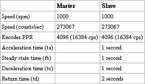
System information:
For this example it is assumed that the Master and Slave components (motors, gearboxes etc.) are identical.
|
Note: |
Speed(cps) = (Speed(rpm) * Encoder(cpr)) / 60 |
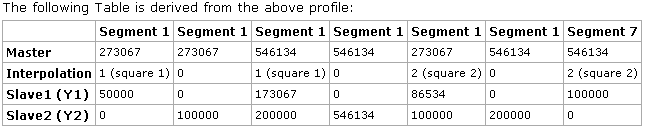
The table below shows how the CAM table should be constructed.

This example is to simply demonstrate the ease of use of Multi-interpolation feature with the CAMBOX function block, when applying to a flying shear profile. With Real Flying shear type application it is deemed the responsibility the user to ensure correct velocities, distances, accelerations and accuracy is achieved.
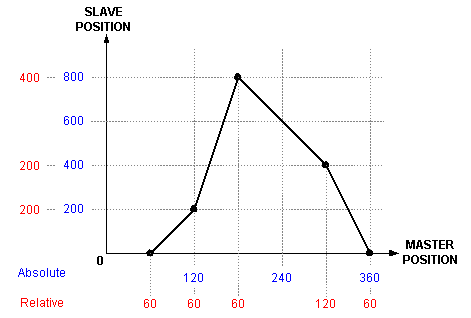
The following diagram shows the profile when using the above settings.

Calculating CAM co-ordinates from positional Information
This method demonstrates how to calculate the Master co-ordinates for a trapezoidal Velocity profile from the following position information: -
1. Master overall distance (Pmt)
2. Slave overall distance (Pst)
3. Slave acceleration distance (Psa)
4. Slave deceleration distance (Psd)
With reference to the diagram below the following calculations can be deduced: -
Slave Steady State Distance (Pss) = Pst - Psa - Psd
Blue Shaded area (Psf) = (2*Psa) + Pss + (2*Psd)
Master Acceleration Distance (Pma) = (2*Psa / Psf) * Pmt
Master Steady State Distance (Pms) = (Pss / Psf) * Pmt
Master Deceleration Distance (Pmd) = (2*Psd / Psf) * Pmt
Velocity Check:
Final velocity for acceleration = Master Velocity * ((2 * Psa) / Pma)
Start velocity for deceleration = Master Velocity * ((2 * Psd) / Pmd)
Steady State Velocity = Master Velocity * (Psa / Pma)

Calculating CAM co-ordinates from time and distance information
This method demonstrates how to calculate the Master co-ordinates for a trapezoidal Velocity profile from the following position information: -
Acceleration time (X1)
Constant speed time (X2)
Deceleration time (X3)
Slave total distance (Pst)
Velocity of master (Vm)
With reference to the diagram below the following calculation can be deduced: -
Using Xt = (X1/2) + X2 + (X3/2)
Slave Acceleration Distance (Psa) = (((X1 / Xt) * Pst) / 2)
Slave Steady State Distance (Pss) = ((X2 / Xt) * Pst)
Slave Deceleration Distance (Psd) = (((X3 / Xt) * Pst) / 2)
Xmt = X1 + X2 + X3
Total distance of the master will be:
Pmt = Xmt * Vm
Master Acceleration Distance (Pma) = ((X1 / Xmt) * Pmt)
Master Steady State Distance (Pms) = ((X2 / Xmt) * Pmt)
Master Deceleration Distance (Pmd) = ((X3 / Xmt) * Pmt)
The Constant speed slave Velocity will be
Vs = Pss / X2
Check that your calculations are correct:
Pst = Psa + Pss + Psd
Pmt = Pma + Pms + Pmd

Switching Position References between CAM and Profile Position
This example demonstrates how to maintain the Current Position reference when switching between CAMBOX and position reference, (Using Sramp profile generator). The CAMBOX is configured with Relative Start bit2 = 0 and Reset function bit3 = 1.
This example does not cater for bumpless velocity transitions between each reference for on-the-fly switching.

CAM Tables information
There are two tables that are required for the 'X' axis, (Master) and 'Y' axis, (Slave) that hold their respective co-ordinate positional data, a third table maybe also required if multi-interpolation is used. The UD70/MD29 uses arrays to hold each table data, where the element data type is +/-32bit integer. Each element of the 'X' and 'Y' axis data is entered with reference to its' axis units, (e.g. encoder counts, time, velocity, etc).
The 'X' and 'Y' arrays can be of different types, constant or dynamic, (variable) arrays.
Constant arrays are defined when the program is compiled, and cannot subsequently be changed unless the program is re-compiled. Constant arrays share the same memory as used for the DPL program, thus the only limitation is that the compiled program size does not exceed the maximum program size for the particular target.
Dynamic arrays use RAM, so the total number of array elements is far smaller. The advantage of a dynamic array is that the DPL program can change element values, while the cam function is in use. If array elements are modified, changes should be completed before the CAM pointer gets to within at least 3 elements.
Refer to the target specifications for more information on the size of the arrays that can be used.
Each table is configured with Relative Co-ordinates, meaning each co-ordinate value is with reference to previous co-ordinate. For example: -

Relative co-ordinate = Present Absolute co-ordinate - Previous Absolute co-ordinate
________________________________________________________________________________