

Overview of the Example
The remaining stages in the Quick Start will show how to create and execute the following program.

The program contains two tasks: Initial and Clock. These tasks will be executed automatically by the target. The Initial task will be executed once by the target when the user program starts executing. The Clock task will be periodically executed once the Initial task has completed.
The example program uses a RAMP block to generate a triangular waveform. The code in the Initial task initialises some programs variables and ensures that the target parameters are set to execute the Clock task once every 10 milliseconds. The Clock task performs a linear RAMP from the positive value of drive parameter #18.20 to its negative value. The value of #18.20 is limited to +/- 1000.
|
Note: |
In SYPT all parameter numbers are preceded with a # character. For example #18.20 means parameter 20 in menu 18. |
UpRate% and DownRate% are program variables. A program in SYPT can define and use as many variables as desired (up to the limit of the target RAM size). Variables with names ending in a % are 32-bit signed integers.
The next quick start stage is:
Create a Project and Adding a Drive
Create a Project and Adding a Drive
This is stage 2 of the quick start example for SYPT.
In this stage a new project will be created and a node added for which a program will be created in the next stage.
Step 1 - Start SYPT and Create a Project
Start SYPT. The SYPT startup dialog will be displayed as follows.

Ensure that the Start a New Project option is selected and that the Network Type field has been set to CT-RTU. Press OK. The SYPT Configuration Editor will then be displayed looking something like the following.

Step 2 - Add A Unidrive SP and SM-Applications option
To add a node to the project double-click the new node hotspot shown to the right of the PC. The Node Properties dialog is displayed.

Make sure that the Drive/ Target field has a Unidrive SP drive type selected. Ensure that the Node ID field has the value 1 and the On Network field has the value CT-RTU. When a Unidrive SP node is added into a project, an SM-Applications option is automatically placed in option slot 3. To verify this, select the Option 3 pane at the top of the dialog.

Ensure that the Option Type is SM-Applications and that the On Network field has the value No Network. Press OK. The Unidrive SP is added into the project with an SM-Applications option in slot 3.

Step 3 - Save the Project
From the File menu, choose Save Project. The Save Project As dialog is displayed.

In the Name field enter QuickExample and press Save. SYPT saves the project.
This is the end of stage 2 of the Quick Start example.
The next Quick Start stage is:
Editing the Program
The previous Quick Start stage was:
Overview of the Example
For more information on the editing actions performed in this section, see:
Starting SYPT
Creating Projects
Saving Projects
Inserting Nodes
Editing the Properties of Networks
![]()
Editing the Program
This is stage 3 of the quick start example for SYPT.
In this stage the example program will be created ready for building and downloading to a target in the next stage.
Step 1 - Open the DPL Editor for the SM-Application program
In the Configuration Editor, select the SM-Applications in slot 3 of the Unidrive SP. When selected the option slot goes blue as follows.

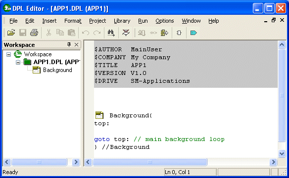
Open the DPL Editor for the node by double-clicking on the SM-Applications option OR in the Edit menu choosing the Node Program option. The DPL Editor will open showing the default program created for the option. The default program contains an empty Background task.
Step 2 - Enter the Initialisation Code
In this step initialisation code is entered. The code will initialise the variables used in the program and change the setup parameters for the option to ensure that the Clock task we will enter later runs at the correct rate. Initialisation code is best placed in the Initial task which is executed once by the target when the user program starts running.
To create the Initial task select the Background node in the tree in the Workspace on the left of the DPL editor. Right-click to display a popup menu and choose Insert Task/ Section. The Insert Task dialog is displayed.

Ensure the Initial Task is selected and press OK. An empty Initial task will be inserted into the main DPL view above the Background task.

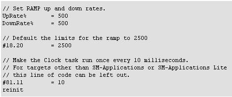
Enter the following code
inside the Initial task.
The DPL Editor should now look like:

Step 3 - Create the Clock task and remove the Background task
In this step the Clock task is created. We do this in the same way as the Initial task was created in the previous step. Select the Background node in the tree in the Workspace on the left of the DPL editor. Right-click to display the popup menu and choose Insert Task/ Section. Ensure the Clock task is selected and press OK to insert a Clock task into the program above the Background task.
To delete the Background task select the Background node in the tree in the Workspace, right-click to bring up the popup menu and choose Delete.
The DPL Editor should now look like:

Step 4 - Enter a Quick Ladder diagram to Limit the RAMP
In this step a Quick Ladder diagram is entered at the start of the Clock task. The diagram will limit the value of parameter #18.20 which is used in the program to set the requested limits of the RAMP. The limiting function does not have to be done using a Quick Ladder diagram - it could be done in DPL or function block - but doing the LIMIT in Quick Ladder serves as an example of how to use a diagram in a program.
With the mouse, left-click inside the Clock task in the main DPL view on the blank line just under the text // put your section code here. Right-click and from the popup menu choose Insert Quick LD diagram. A new window is opened allowing a QLD diagram to be entered. The menus and toolbars in the DPL editor switch to allow editing of the diagram.

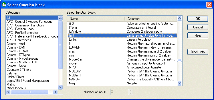
Press F6 to insert a function block. The Select Function Block dialog is displayed. Scroll down the list of available blocks and select the LIMIT block.
|
Note: |
If the Select function block dialog was not displayed, type Ctrl+Z to undo insertion of the function block and in the Options menu choose Auto Prompt For Input. Repeat the last step to reinsert the function block. |
Press OK. A new ladder rung is inserted into the diagram containing the LIMIT block.

The inputs and output for the LIMIT block now need to be specified. Double-click the area just to the left of the IN input to the function block. The Select variable dialog is displayed allowing a variable, parameter or number to be associated with the input. The variables and parameters already entered into the Initial Task appear in the dialog. Select #18.20 and press OK.
|
Note: |
If the dialog does not show the variables and parameters already entered into the Initial task, press the Scan button to make the dialog refresh its displayed list of symbols. |

The diagram should now look like:

Double-click to the left of the limit input and enter 1000 into the Select variable box then press OK. Double-click to the right of the Q output and select #18.20 in the Select variable dialog then press OK. The diagram should now look like:

Right-click the mouse inside the diagram and from the popup menu choose Goto Preview. The main DPL view will be displayed.
Step 4 - Enter the call to the RAMP function block
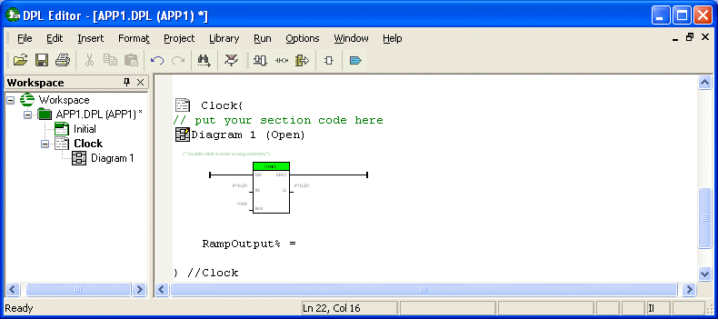
Click the mouse inside the Clock task under the Quick Ladder diagram. Enter the text RampOutput% = so that the Clock task looks like:
Press F7 to display the Select function block dialog. Scroll down the list of available blocks and select the RAMP block. Press OK to insert a template function block call into the Clock task.

Change the values being passed into the RAMP block to match those below
![]()
Finally, enter the following code which swaps the RAMP limits when a limit is reached.

The program is now complete. Save the program by choosing Save from the File menu.
This is the end of stage 3 of the Quick Start example.
The next Quick Start stage is:
Building and Downloading the Program
The previous Quick Start stage was:
Create a Project and Adding a Drive
For more information on the editing actions performed in this section, see:
Opening and Closing Programs
Editing Programs