- •Introduction
- •1 Quick Start
- •Overview of the Example
- •Create a Project and Adding a Drive
- •Editing the Program
- •Building and Downloading the Program
- •Monitoring Operation of the Program
- •Importing sm-Applications Lite syptLite Programs
- •Upgrading from the dpl Toolkit
- •Loading a dpl File from disk
- •Uploading a dpl File from a Target Node
- •Starting sypt
- •Configuration Editor
- •Menu Bar
- •Toolbars
- •View toolbar for the Hardware Architecture view
- •Status Bar
- •Hardware Architecture View
- •Link Architecture View
- •Cyclic Data View
- •Specifying Workbench Options
- •Dpl Editor
- •SyptLite
- •Watch Window
- •Menu Bar
- •Managing Projects
- •Creating Projects
- •Opening Projects
- •Saving Projects
- •Viewing Project Properties
- •Cloning Projects
- •Closing Projects
- •Printing Projects
- •Defining a Project Header
- •Inserting Nodes
- •Selecting Nodes
- •Editing the Properties of Nodes
- •Editing Node Descriptions
- •Deleting Nodes
- •Cutting, Copying, and Pasting Nodes
- •Rearranging Nodes
- •Networks
- •Unreachable Nodes
- •Inserting Networks
- •Selecting Networks
- •Deleting Networks
- •Editing the Properties of Networks
- •Pc Communications Settings
- •Rearranging Networks
- •Splitting Network Rails
- •Merging Network Rails
- •Cyclic Data Links
- •Inserting Data Links
- •Inserting Broadcast Links
- •Defining Cyclic Data
- •Viewing Cyclic Data
- •Selecting Links
- •Rearranging Links
- •Deleting Data Links
- •Editing Source/Destination Node Descriptions
- •Annotations
- •Inserting Annotations
- •Editing the Contents of Annotations
- •Formatting Text in Annotations
- •Deleting Annotations
- •Dpl Programs
- •Creating Programs
- •Opening and Closing Programs
- •Saving Programs
- •Editing Programs
- •Specifying the Floating-Point Model
- •Inserting Sections
- •Inserting Diagrams
- •Inserting Variables, Parameters or Numbers
- •Inserting Function Block Calls
- •Inserting Files
- •Inserting the Date and Time
- •Selecting Items in Programs
- •Cutting, Copying, and Pasting Items
- •Finding and Replacing Text
- •Go to a Source Line
- •Editing Diagram Titles
- •Editing/ Viewing the Properties of Programs
- •Printing Programs
- •Templates
- •Dpl Syntax Templates
- •Defining a Template
- •Dpl Templates Dialog
- •Defining a Template Category
- •Deleting a Template/ Changing a Template Name
- •Deleting a Category/ Changing a Category Name
- •Template Shortcut keys
- •Inserting a Template into a Program
- •Creating a Library
- •Specifying Function Block Properties
- •Library Folder Structure
- •Viewing Library Properties
- •Library Manager
- •Referencing and Using a Library
- •Removing a Reference To a Library
- •Exporting a Library
- •Importing a Library
- •Switching the Configuration Editor Online
- •Switching the Configuration Editor Offline
- •Node Detection and Indications
- •Successfully Detected Nodes
- •New Node
- •Nodes Not Found
- •Cyclic Data Mismatches
- •Cyclic Master and Trip Indications
- •Refreshing the View of Nodes While Online
- •Adding Detected Nodes
- •Deleting Target User Programs
- •Building Applications
- •Showing Build Errors
- •Downloading Node Programs
- •Uploading Node Programs
- •_______________________________________________________________________________________________ Accessing Diagnostic Information for Nodes
- •Accessing Identification Information for Nodes
- •Monitoring the Values of Variables and Parameters
- •Watching Values in the dpl Editor
- •Setting Up a Watch List
- •Opening and Closing Watch Lists
- •Saving Watch Lists
- •Adding Variables and Parameters to a Watch List
- •Selecting Watch List Items
- •Cutting, Copying, and Pasting Watch List Items
- •Removing Items from a Watch List
- •Editing the Properties of Watch List Items
- •Rearranging the Order of Watch List Items
- •Changing the Values of Variables or Parameters
- •Controlling Program Execution
- •Stopping and Starting Programs
- •Pausing and Resuming Programs
- •Stopping and Stepping Tasks
- •Running Tasks
- •Using Breakpoints
- •Switching dpl Programs to Editing Mode
- •Resetting Node Programs
- •Resetting Drives
- •Abs - Absolute
- •Ansiread - ansi Master Command
- •Ansireadn - ansi Master Command
- •Ansireply - ansi Master Command (ud70 and md29)
- •Ansireply - ansi Master Command (sm-Applications)
- •Ansiwrite - ansi Master Command
- •Ansiwriten - ansi Master Command
- •ApcSetRunMode
- •ApcReset
- •ApcGetOutputSpeed
- •ApcGetOutputSpeedRpmx10
- •ApcSelectAbsoluteMode
- •ApcSelectRelativeMode
- •ApcReadPar
- •ApcSetPositionResetOffset
- •ApcResetSourcesOnDisable
- •ApcDoNotResetSourcesOnDisable
- •ApcSetReferenceSource
- •ApcSetFeedbackSource
- •ApcSetNumOfTurnsBits
- •ApcEnableRefSourceMarker
- •ApcDisableRefSourceMarker
- •ApcEnableFbckSourceMarker
- •ApcDisableFbckSourceMarker
- •ApcResetRefSourceMarkerFlag
- •ApcResetFbckSourceMarkerFlag
- •ApcResetRefSourceFreezeFlag
- •ApcResetFbckSourceFreezeFlag
- •ApcInvertRefSource
- •ApcDoNotInvertRefSource
- •ApcInvertFbckSource
- •ApcDoNotInvertFbckSource
- •ApcSetReferencePosition
- •ApcSetFeedbackPosition
- •ApcGetReferenceStatus
- •ApcGetFeedbackStatus
- •ApcSelectReference
- •ApcSelectActionOnFreeze
- •ApcSetStopMode
- •ApcSetPositionSetPoint
- •ApcSetSpeedSetPoint
- •ApccamInitialise
- •ApccamInitialise1
- •ApccamInitialise2
- •ApccamInitialise3
- •ApcSetCamStartIndex
- •ApcSetCamSize
- •ApcSetCamDeltaSegLimit
- •ApcSetCamInterpolationMode
- •ApcSetCamOutRatioNumerator
- •ApcSetCamOutRatioDenominator
- •ApcSelectCamAbsoluteReset
- •ApcSelectCamZeroReset
- •ApcSetCamAbsResetIndex
- •ApcSetCamAbsResetPositionInSeg
- •ApcEnableCamSingleShot
- •ApcDisableCamSingleShot
- •ApcSetDigLockMode
- •ApcSetDigLockRatioNumerator
- •ApcSetDigLockRatioDenominator
- •ApcSetDigLockLockingSpeed
- •ApcSetDigLockLockingPosition
- •ApcSetSpeedOffset
- •ApcSetPositionOffset
- •ApcDisableRigidLock
- •ApcEnableProfile
- •ApcDisableProfile
- •ApcSetProfileAccelRate
- •ApcSetProfileDecelRate
- •ApcSetProfileMaxSpeedClamp
- •ApcSetPGain
- •ApcSetPGainSpeedClamp
- •ApcEnableExternalRefSpeed
- •ApcDisableExternalRefSpeed
- •ApcSetExternalRefSpeed
- •ApcEnableExternalRefPosition
- •ApcDisableExternalRefPosition
- •ApcSetExternalRefPosition
- •ApcSetOutputRatioNumerator
- •ApcSetOutputRatioDenominator
- •ApcSetupOutputChannel
- •ApcEnableOutputChannel
- •ApcDisableOutputChannel
- •ApcWriteOutputChannel
- •ApcToUserPosition
- •ApcToUserVelocity
- •ApcToUserAcceleration
- •Arrayget - Get Array Element
- •Arrayset - Set array element
- •Arraysort
- •Arraystat
- •Assram - Associate an array with a file
- •Autosync - ctNet Sync Master Redundancy
- •Autosyncerror
- •Average - Running Average
- •Bcd2bin - Binary-coded Decimal to Binary Conversion
- •Bin2bcd - Binary to Binary-coded Decimal Conversion
- •Bcd2seg - Binary-coded Decimal to Seven-segment Display Data
- •Blkdef - Block Parameter Write
- •Bridge - rs485 Serial Protocol Function
- •Cambox - cam function generator
- •Cambox2 - cam function generator
- •Cambox/cambox2 - cam information
- •Caminit - cam Table Initialise
- •CanConfigEvent
- •CanGetNodeAddr
- •CanReady
- •CanSetup
- •CanStatus
- •CanStatusAll
- •Checknode - Check Existence of Node on ctNet
- •CloseSmartCard
- •Cmodexfer
- •Cmp - Comparison Block
- •Condparw - Conditional Parameter Write
- •ConvertBackwards
- •ConvertForwards
- •Cos - Cosine Function
- •Crc16 - Cyclic Redundancy Check
- •Ctd - Down Counter
- •Ctu - Up Counter
- •Ctud - Up/ Down Counter
- •Ctnetdiagnostics
- •CtSyncDisableOutputChannel
- •CtSyncEnableOutputChannel
- •CtSyncGetSlaveReferences
- •CtSyncSetMasterReferences
- •CtSyncSetupOutputChannel
- •CtSyncWriteOutputChannel
- •Datastuff
- •Decoder4/decoder8
- •Digsel8 - Digital Select Block
- •IDMux/ fDMux / iDMux8 - De-multiplexers
- •Dterm - Differentiator Block
- •Editfastlink/editslowlink - ctNet Cyclic Link Editing
- •Egb / egb2
- •EnableCanTrips
- •Encoder4/encoder8 - Binary Encoder Blocks
- •Exp - Exponential Function
- •Filter - First-order Digital Filter
- •Float - Integer to Floating Point Conversion
- •Float32
- •Getchar - Read rs485 Port
- •GetNextSmartCardFile
- •GetParAttr
- •GetSamplesPerSec
- •GetTaskId
- •Home1 - Homing function
- •Home2 - Homing function
- •HiLoDet - Max and min value detection
- •Int - Floating Point to Integer Conversion
- •ITerm - Integrator Block
- •IWindow
- •ILimit/ fLimit
- •ILimit2/ fLimit2
- •IInvert/fInvert
- •Ln - Natural Logarithm
- •LinInt - Linear Interpolation
- •Modexfer
- •Mpot - Motorised Pot
- •Muldivrm
- •IMux / fMux / iMux2 / fMux2 / iMux8 - Multiplexers
- •Nand4 - Four-input nand Gate
- •Neg - Inverts Input
- •Netreply
- •Netstatus
- •Nor4 - Four-input nor Gate
- •OpenReadSmartCard
- •OpenWriteSmartCard
- •Or4 - Four-input or Gate
- •IOs/ fOs - Offset-Scale
- •Pfixread - Fixed Precision (3 dps) Parameter Read
- •Pfixread6 - Fixed Precision (6 dps) Parameter Read
- •Pfixwrite - Fixed Precision (3 dps) Parameter Write
- •Pfixwrite6 - Fixed Precision (6 dps) Parameter Write
- •Pid - pid Block
- •Posloop - Position Loop Controller
- •Posloop2 - Position Loop Controller
- •Precisiontimer
- •Pt - Pulse Timer
- •Ptd - Pulse Timer
- •Putblock
- •PutBottomWord
- •Putchar - Write Character to rs485 Port
- •Putkey - Write Character to Port
- •PutTopWord
- •RamLength
- •Ramp - Linear Ramp
- •Readnet
- •Readnetb
- •ReadReadOnlyBit
- •ReadSmartCardByte
- •Reg - Registration Block
- •ResetCanTimer
- •Rs/sr : Event Memory Latches
- •RtuReadRegs
- •RtuReadParas
- •RtuReadInputRegs
- •RtuPresetRegs
- •RtuPresetParas
- •RtuMasterReply
- •RtuMasterStatus
- •Runtime
- •Scheduleevent
- •SetConverterDenominator
- •SetConverterNumerator
- •SetCtnSync
- •SetRamLength
- •SetUserId
- •Shiftlr
- •SignedBottomWord
- •SignedTopWord
- •Sin - Sine Function
- •ISo/fSo : Scale-Offset
- •Splitter
- •SpGateway - ctNet to fieldbus gateway
- •Sq1int/ Sq2int - Square Interpolation
- •Sqr - Square Root Function
- •Sramp - s-Ramp Profile Generator Function
- •Ssramp - s-Ramp Profile Generator Function
- •Stuff2 / stuff4 / stuff8 - Bit Stuffers
- •Tan - Tan Function
- •Tcyclic - Cyclic Timer
- •ToffRet
- •Trl - Triggered Latch Function
- •UnAssram
- •UnsignedBottomWord
- •UnsignedTopWord
- •UserToApcAcceleration
- •UserToApcPosition
- •UserToApcVelocity
- •Vel2pos - Velocity Profile Integrator
- •Writenet
- •Writenetb
- •Wrnet - ctNet Write Command
- •Wrnetb - ctNet Block Parameter Write Command
- •WriteReadOnlyBit
- •WriteSmartCardByte
- •Xor4 - Four-input xor Gate
- •SmartCard Example Program
- •Supported Languages
- •Variables, Parameters, Constants and Data Types
- •Variables
- •Bit Access For Variables
- •Predefined Variables
- •Parameters
- •Plc Registers
- •Data Types
- •Constants
- •Numbers
- •Variable and Parameter Scope
- •Aliases
- •Program Structure
- •Subroutines
- •User-Defined Function Blocks (udfBs)
- •Calling udfBs
- •Udfb Argument Restrictions
- •Udfb Instances
- •Udfb Code Sections
- •Dpl (Drive Programming Language) Reference
- •Directives
- •Operators
- •Conditional Operators
- •Comments
- •Constructs
- •Variable Assignment
- •If ... Then
- •For Loop
- •Function Block Call
- •Ld/ fb Elements
- •Ld/ fb Coil Types
- •Ld/ fb Contact Types
- •Ld/ fb Order of Execution
- •Qld (Quick Ladder Diagram) Reference
- •Qld Elements
- •Qld Coil Types
- •Qld Contact Types
- •Advanced Position Controller
- •Programming Hints and Tips
- •Copyright
Monitoring Operation of the Program
This is stage 5 of the quick start example for SYPT.
In this stage the example program is monitored as it executes on the SM-Applications target.
To begin this stage, the DPL editor should be in the state it was in at the end of stage 4 - online and communicating with the target.
To monitor execution of the user program, perform the following steps:
Step 1 - Ensure the program is running
At this stage, the DPL Editor should look something like the following picture.
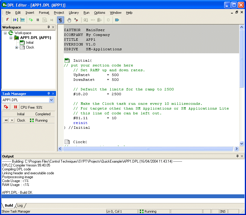
Note the Running status shown in the status bar at the bottom of the DPL Editor. The picture also shows the Task Manager open in the DPL Editor on the left under the Workspace.
The status bar may show a Stopped status if the program is not running. If this is the case press F3 to start execution of the program - the Stopped status will then change to Running.
If the Task Manager is not open, type Ctrl+T to open it.
Notice that the Task Manager shows the status of all tasks in the program - the Initial task has run once when the program started and has completed execution and the Clock task is still running.
Step 2 - Examine variables and parameters
The code in the Initial task set drive parameter #18.20 to 2500. The LIMIT block in the Clock task should have limited the value of #18.20 to +/-1000 however. At the end of the clock task, #18.20 is negated whenever the ramp output hits its target value.
To check that #18.20 is being limited to +/- 1000, hover the mouse cursor over the text #18.20 in the DPL view - the value of #18.20 will be displayed. If the mouse remains over #18.20, the displayed value will toggle between +/- 1000.
Try hovering the mouse cursor over other variables and parameters in the DPL view to examine their values. The RampOutput% variable will be rapidly counting up and down as it ramps between +/-1000.
Step 3 - Examine the RAMP output in more detail
To examine the RAMP output in more detail, click the mouse in the RampOutput% variable in the DPL view and then right-click and from the popup menu choose Send symbol to Watch Window. The Watch Window will open showing the current value of the RampOutput% variable.
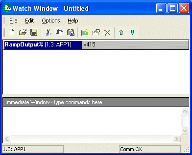
In the Watch Window, double-click on the RampOutput% variable to show the Properties dialog. Check the Curve box and set the Curve Min and Max to -1000.0 and 1000.0 as shown in the following picture.
Press OK. The Watch Window will now show a trace of RampOutput%.
Select the bottom of the grey panel showing the RampOutput% value and drag it down to make the curve larger.
Step 4 - Modify Values
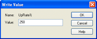
In the DPL Editor, double-click the UpRate% variable passed as the acceleration rate argument to the RAMP function block. The WriteValue dialog will be displayed. Enter the value 250 and press OK.
RampOutput% will now ramp upwards more slowly than it ramps downwards. The Watch Window should now look like the following.
In the bottom half of the Watch Window (the Immediate Window) enter the text UpRate% = 500 and press the RETURN key. The value of the UpRate% variable will be set to 500 (its original value) and RampOutput% will ramp up as fast as it ramps down.
Step 5 - Monitor a diagram
In the DPL Editor, double-click on the QLD diagram preview (the diagram containing the LIMIT function block call) to open the diagram in its own window. The diagram opens and the value of parameter #18.20 is displayed next to the LIMIT input and output. As the value of #18.20 changes the value is updated in the diagram.
This is the end of the Quick Start example. The DPL Editor and Configuration Editor can now be closed.
The previous Quick Start stage was:
Building and Downloading the Program
For more information on the editing actions performed in this section, see:
Debugging Applications
________________________________________________________________________________
Upgrading from SYPT V1.X
Users upgrading from SYPT V1.X to SYPT Pro will find a number of differences in the look and operation of SYPT. At the same time many elements of SYPT Pro will be familiar to existing users. The basic structure of SYPT remains - there is still a Configuration Editor and a DPL Editor but the views and components within them have been extensively modernised.
SYPT Pro allows the user to do everything he could do with SYPT Version 1. Programs can still be written in DPL, Quick Ladder and LD/ FB but the editors, debugging and monitoring features are more powerful.
SYPT 1 projects can be directly opened in SYPT 2. When an old project is opened it is upgraded to SYPT 2 format and the original project is backed up into a ZIP file (SYPT1BAK.ZIP) in the project folder. Once a project has been opened in SYPT 2 it can no longer be opened in SYPT 1 - the original project must be restored from the ZIP file.
SYPT Pro is capable of uploading SYPT 1 programs (with embedded source files) from targets. Once a program has been compiled and downloaded to a target using SYPT Pro it is no longer possible to upload the embedded source file back into SYPT 1.
SYPT Pro contains a version of SYPTLite which is used as the program editor for the Unidrive SP Onboard PLC. The new Configuration Editor will launch SYPTLite to edit Unidrive SP programs and will launch the DPL editor to edit SM-Applications, SM-Applications Lite, UD70 and MD29 programs. Any existing standalone version of SYPTLite can still be used after SYPT is installed BUT the standalone SYPTLite and SYPT Pro cannot be executed at the same time. Any program created with the standalone version of SYPTLite can be opened with the version of SYPTLite included in SYPT and vice-versa.
For an overview of the new user interface provided by SYPT Pro see:
SYPT Components
For an overview of upgrading from SYPTLite to SYPT Pro see:
Upgrading from SYPTLite
SYPTLite users who are upgrading to SYPT Pro will find that SYPT is a far more powerful programming platform. For program development, SYPT mainly uses the DPL Editor. This editor allows programs to be written in DPL (a high level textual language), LD/ FB (Ladder and Function Block languages) and QLD (Quick Ladder). Quick Ladder is the ladder programming language used in SYPTLite and should be very familiar to SYPTLite users.
SYPT contains a special version of SYPTLite which is used to develop programs for the Unidrive SP Onboard programming capability. The version of SYPTLite in SYPT is very similar to the standalone version.
However, within SYPT, programs are developed for the SM-Applications Lite module using the DPL editor. Using the DPL editor to write programs for the SM-Applications Lite module brings many advantages:-
1. More programming languages are available to develop user programs.
2. More function blocks are available to the user program. Up to 200 more predefined blocks are available.
3. Programs can be developed using more than one task in the SM-Applications Lite - Initial, Background, Clock, Pos0, Pos1, Event and Error tasks can all be used in a single program.
4. More code space and RAM are made available in the target allowing bigger programs to be developed.
5. A program can use variables as well as parameters.
6. Floating-point maths is supported. Parameters with decimal places are not read and written in fixed 3 decimal place format.
7. Aliases can be created for constant numbers, e.g. $define PI 3.142 as well as for parameters.
It should also be noted that the standalone version of SYPTLite can still be used when SYPT is installed. SYPT does not overwrite or disable any version of SYPTLite already installed and the user can still install SYPTLite or upgrade SYPTLite when SYPT is present on a PC. The only restriction is that the standalone SYPTLite and SYPT cannot be executed at the same time. Of course, the version of SYPTLite included in SYPT can be executed at the same time as the DPL editor - both can be open and being used to develop programs and both can be open and online monitoring targets and downloading programs.
If a program was developed for the Unidrive SP Onboard target in the standalone version of SYPTLite it can be directly opened or inserted into the version of SYPTLite included in SYPT.
If a program was developed for SM-Applications Lite then to work with the program in SYPT, the program needs to be converted into a format suitable for the DPL Editor. See Importing SM-Applications Lite SYPTLite Programs for instructions on how to import a SYPTLite file into the DPL editor.
For an overview of the new user interface provided by SYPT Pro see:
SYPT Components
For an overview of upgrading from SYPT Version 1 to SYPT Pro see:
Upgrading from SYPT V1.X