

higher pressure portion of the sound waves traveling faster than the slower portions. These nonsinusoidal waves contain additional frequencies in multiples of the fundamental or originating frequency. These even and odd multiples of the fundamental frequency are called harmonic frequencies. When using harmonic imaging the fundamental frequency is filtered out and second harmonic waves are used to generate the ultrasound image. This imaging mode is used to enhance the definition of endocardial borders and reduces the generation of artifacts, especially in patients with poor acoustic windows. Poor image quality is usually the result of factors like fat, muscle, and fibrosis that are present before the sound beams have even entered the tissue of interest. These factors create variations in the speed of sound and create distortion of the sound beam and the resulting ultrasound image. The harmonic frequencies are created in the chest from the reflected sound and not at the chest wall where most artifacts originate; this results in the alleviation of imaging artifacts especially side lobe artifact. It also enhances contrast resolution of the ultrasound image. The result is improved image quality with reduced artifact generation, enhanced endocardial details, improved contrast, and decreased noise. There are some patients in which harmonic imaging does not improve image quality because of frequency dependent attenuation of sound.
Transducers and Resolution
Transducers are the source of sound in diagnostic ultrasound. Transducers contain piezoelectric crystals that are deformed by electrical voltage and generate sound. These crystals, often called elements, are also able to receive sound and convert it back into electrical energy. The thickness of the crystal dictates the basic operating frequency of the transducer. Wavelength will be one-half of the element thickness so decreased crystal thickness produces shorter wavelengths and higher frequencies.
Pulse Repetition Frequency
Transducers used in pulsed-echo applications do not transmit sound continuously. They send sound waves out in short bursts and receive sound the remainder of the time. This is called pulsed ultrasound. The number of pulses per second is referred to as the pulse repetition frequency (PRF). PRF is measured in Hz. The PRF for example would be 10 Hz if there are 10 pulses per second (Figure 1.10). Each pulse may have any number of cycles, but in diagnostic ultrasound, there are generally two or three cycles per pulse. The number of cycles per pulse is controlled by damping materials within the transducer.
Figure 1.10 Transducers send out sound waves in short bursts called pulses. The number of pulses per second is called the pulse repetition frequency (PRF), measured in Hz. Each pulse has a duration based on the wavelength and number of cycles.

The duration of a pulse, measured in microseconds, and pulse length, measured in mm, decreases if the frequency of the sound wave increases since the wavelengths are shorter (Figure 1.10). By the same token, lower frequency sound waves have longer wavelengths so pulse duration and length are increased. Accurate ultrasound images can only be generated if all reflected and scattered echoes are received at the transducer before the next pulse is generated. The transducer assumes that the echoes it receives are products of its last burst. If an echo has not been received before the next burst and it arrives at the transducer shortly after the second burst, then the instrument “thinks” very little time has elapsed since it was transmitted and received. Since time is used along with the speed of sound in tissues to determine structure depth, a structure that is actually deeper will be displayed closer to the body surface (Figure 1.11). Pulse repetition frequency must decrease as deeper structures are imaged for accurate depth assessment.
Figure 1.11 A sound wave must be transmitted, reflected, and received by the transducer before the next pulse is generated. The number of pulses per second is the pulse repetition frequency. Pulse repetition frequency must decrease for accurate structure localization when interrogating deeper structures.

Sound Beams
Sound beams generated by transducers are three-dimensional. They not only have pulse length and duration but they also have beam widths and thicknesses. Beam diameter determines the width within the scan plane and the thickness perpendicular to the scan plane.
Sound beams do not remain the same width as they travel through a medium. In an unfocused transducer the sound beam starts out with a width equal to the transducer diameter and, as it travels through the tissues, it diverges (Figure 1.12). The distance from the transducer element to where it diverges is the beam’s near field. The area beyond the near field is the far field. Near field length is directly proportional to the beam diameter and inversely proportional to wavelength (Figure 1.12). For two transducers of the same frequency, the near field will be longer for the transducer with the larger diameter. For two transducers with the same diameter, the near field will be longer for the higher frequency transducer.
Near field = radius2/wavelength
Larger beam width = longer near field
Shorter wavelength = longer near field
Figure 1.12 Sound beams have a diameter equal to transducer diameter and diverge as they travel out through a tissue. The distance from a transducer element to where the beam diverges is referred to as the near field. The area beyond that is the far field.

Far field divergence is also dependent upon transducer size. Larger diameter transducers produce less divergence in the far field. High frequency transducers with large diameters therefore produce the longest near field and the narrowest far field (Figure 1.12).
When a curved element or lens is used, the beam can be focused and beam width will decrease throughout the entire near field and create a focal zone, but beam width will diverge rapidly beyond this focal point (Figure 1.13). Many transducers today have variable focal zones that the examiner can set.
Figure 1.13 A sound beam can be focused by using a curved element or lens. This decreases beam width within the near field.
If multiple pulses are generated and each pulse is set to a different focal zone, then an elongated focal zone can be created. The transducer simply ignores echoes returning from depths other than the focal depth for any given pulse.

Up to this point only single sound beams have been considered. A single sound beam is used to generate an M-mode image of the heart. This beam travels through the cardiac structures and a onedimensional image is generated. B-mode or two-dimensional imaging uses an array (group) of crystals that are electronically triggered to generate sound waves. It is important to recognize that each sound beam generated by a transducer is affected by pulse length, beam width, focal length, and PRF.
Linear array transducers have multiple elements arranged in a row. Sequences of elements are electronically stimulated at one time (i.e., elements one through four, then elements two through five, etc.) with each group producing one scan line. This produces a high quality image with increased line density within the generated image. Linear array transducers can be modified into curvilinear formats. Phased array transducers stimulate each crystal with a small time interval (less than a microsecond) between them and they are directed through the tissues at slightly different angles (phased) (Figure 1.14). This produces a sector image and these transducers are often called electronic sector transducers. Rapidly stimulating these elements over and over again in sequence produces the moving cardiac images we call real-time ultrasound.
Figure 1.14 Phased array transducers have elements that are stimulated in sequence creating a slightly different angle of transmission through the tissues. This produces a rapidly moving two-dimensional sector image.
Axial Resolution
Resolution is the ability to identify two objects as different. Pulse length, beam width, beam diameter, focal length, and PRF are important physical aspects of transducers that affect the axial, lateral, and temporal resolution of ultrasound images.
Resolution
Axial
Ability to differentiate between two structures along the length of the sound beam
Lateral
Ability to resolve two structures in the plane perpendicular to the sound beam
Temporal
Ability to resolve structures with respect to time, keeping up with the actual events
Axial resolution is the ability to differentiate between two structures along the length of the sound beam. Axial resolution is also called depth or longitudinal resolution. The smaller the axial resolution is, the better the detail of the image.
Transducer frequency plays an important role in axial resolution. Axial resolution is equal to half the pulse length, that is, two structures cannot be closer than half the pulse length to each other in order to be distinguished as two separate things. Remember that pulse length depends upon the

wavelength of the sound and upon the number of cycles per pulse. When one or both of these is reduced axial resolution improves (Figure 1.15). Wavelength decreases as frequency of sound increases, so axial resolution is better with 7.5-MHz frequency sound than with 3.5-MHz frequency sound. Pulse length and duration are shortened by adding damping materials within the transducer or electrical damping within the equipment.
Pulse Length
A pulse may have any number of cycles (generally two to three in echocardiography).
Pulse length decreases with higher frequency sound because of shorter wavelengths and increases with lower frequency sound.
Axial Resolution
Better axial resolution = better image detail
Equal to half the pulse length
Higher frequency transducers have better axial resolution.
↑ Frequency = ↑ Resolution
↓ Frequency = ↓ Resolution
Figure 1.15 Axial resolution improves with increased frequency and decreased pulse length. Two things must be farther apart than one-half the pulse length to be identified as two different structures.
Lateral Resolution
Lateral resolution is the ability to resolve two structures as distinct and different in a plane perpendicular to the sound wave. Lateral resolution is equal to beam width and improves with smaller beam widths. Beam width is affected by 1) focusing the sound waves generated by a transducer, 2) transducer diameter, and 3) transducer frequency.
The narrower the beam width the better the ability to differentiate between two structures in a plane perpendicular to the sound beam (Figure 1.16). Beam width varies along the length of the sound wave but is at its narrowest at the focal zone in focused transducers. Lateral resolution is best (smallest) at the focal zone. Two structures that are side by side within the boundaries of the beam width will not
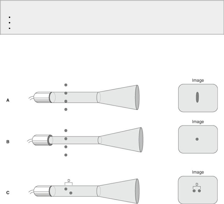
be resolved as two different structures (Figure 1.16). If they are offset a little in depth however, they may be resolved as two different structures based upon axial resolving powers of the transducer (Figure 1.16).
Lateral Resolution
Improves with narrower beam widths
Usually narrowest at focal zones of focused transducers
Best within near field where beam width is narrowest
Figure 1.16 The ability to resolve two structures as different in a plane perpendicular (lateral resolution) to the sound beam depends upon beam width. (A) Two structures that fall within beam width will not be differentiated (B) while two structures that are farther apart than the beam width will be identified as separate. (C) The axial resolving powers of the system may differentiate two structures that fall within beam width when they are offset in depth (D).
Lateral resolution of an image is also best within the near field where beam width is narrowest. A high frequency transducer will have better lateral resolution than a lower frequency transducer of the same size because of its longer near field. Long narrow near fields allow more specific areas of the heart to be imaged, creating less ambiguity about the source of returning echoes (lateral position errors).
Longer near field length, focused transducer beams, and less far field divergence also improve image quality by increasing beam strength. Stronger beams increase the degree of reflection and can travel farther before all the sound is attenuated.