


Most neonate food animals and foals are examined similar to small animals. They are placed on the scanning table in right lateral recumbency for standard imaging planes. Restraint is similar to that in small animals, and this prevents unnecessary movement. A faster and more accurate examination can usually be performed in this manner.
Transducer Selection
Transducer frequency is an important consideration since it affects depth of penetration and resolution of the image. Higher frequency transducers, because of their shorter wavelengths, allow better resolution of structures but less depth penetration. Low-frequency transducers, with longer wavelengths, allow sound waves to travel deeper into tissues before weakening. This is at the expense of resolution.
High frequency transducers create high-resolution images. Try higher frequency transducers before selecting a lower one just to see if it will work.
Use a high frequency transducer to obtain clearer images of near field structures.
Even though depth and resolution are inverse components of transducer frequency, when an appropriate transducer is used, the loss in resolution is not appreciated because structures are larger. High frequency transducers should be used for cats and small dogs. A high frequency transducer can also be used in larger animals in order to improve the resolution of near field structures, like the tricuspid valve.
Medium-sized animals in the range of approximately 30 to 50 pounds can often be imaged with 7.5- to 5.0-MHz transducers. Larger dogs and newborn foals and calves usually require a 5.0-MHz or lower frequency transducer. It is a good habit to try the highest frequency you have before selecting a lower one just to see if it works. This allows you to create the best images for diagnostic purposes. With today’s multifrequency transducers and current technology, high frequency transducers provide better image quality and depth penetration than in the past. Even though an animal weighs 60 pounds, for example, a very narrow thorax may allow the use of a 7.5-MHz transducer and produce excellent images. Large animals like the adult horse or cow almost always require a 2.5-MHz or lower frequency transducer for the sound beams to reach the far wall of the heart.
Switch to a lower frequency transducer when starting the Doppler part of your exam in order to obtain better quality Doppler information.

Apical fourand five-chamber examination planes sometimes require changing the probe to a lower frequency than used to image the patient’s heart for standard right or left parasternal planes through the heart. Imaging from the apex of the heart to its base requires much more depth penetration than views that image the width of the heart from right to left or vice versa across the thorax.
Even when all imaging planes can be obtained with one transducer, change to a lower transducer frequency when obtaining Doppler flow information. Lower frequency transducers provide increased signal strength at greater depths and reduce aliasing during pulsed-wave and color-flow Doppler interrogation. Lower transducer frequencies are also often required to produce a strong enough spectral signal from small regurgitant volumes. Most equipment automatically switches to a lower frequency when Doppler is used.
Two-Dimensional Images
Introduction
Two-dimensional echocardiography uses transducers that transmit multiple beams of sound in the form of a sector or pie. The sector has width, depth, and thickness. Although section thickness is sometimes a factor in image quality, it is not a consideration when describing real-time anatomy. As the sector of sound is sent through the heart, soft tissue reflects sound back to the transducer and appears white on the monitor. The fluid-filled spaces of the cardiac chambers lack the density to reflect sound. These areas appear black on the ultrasound monitor.
Terminology and image orientation are adapted from human echocardiography. Recommendations by the Committee on Standards for Veterinary Echocardiography have been set in order to produce uniform views, and have common terms when discussing an imaging plane (22).
Imagine cutting the heart into slices like a loaf of bread. The slice may follow the length of the loaf, the width of the loaf, or any angle between these planes. Each slice is representative of an echocardiographic plane. The imaging planes described in the following sections are recommended for standard examinations and represent identifiable and consistently recognizable landmarks within the heart. Many other imaging planes can of course be obtained, and structure identification is made as the image changes from a standard view to a non-standard plane through the heart.
Longitudinal (sagittal) images are those in which the imaging plane follows the length of the heart from base to apex (Figure 2.8) and are often referred to as long-axis views. Transverse images are those in which the imaging plane shows the width of the heart from right to left (Figure 2.9), and these are usually referred to as short-axis views. There are several angled or oblique views of the heart. These views show some structures in their length and others in a plane between the long and short axis.
Long axis: Sagittal imaging planes that follow the length of the heart
Short axis: Transverse imaging planes that follow the width of the heart
Figure 2.8 Longitudinal or long-axis views follow the length of the heart from base to apex.

Figure 2.9 Transverse or short-axis images follow the width of the heart from right to left.
Apical two-, four-, and five-chamber images can be obtained from left parasternal or subcostal transducer positions. There are also several longitudinal and oblique planes that require imaging from the left side of the animal. These planes can be obtained in dogs and cats by simply leaving the animal

in right lateral recumbency on the table and scanning from above, or the animal may be placed in left lateral recumbency on the exam table with transducer placement under the table. It is easier to obtain the left parasternal views when small animals are placed in left lateral recumbency on the table.
Standard left and right parasternal long-axis views of the heart are displayed with the base of the heart toward the right side of the monitor and the apex to the left. Transverse images are displayed so that the pulmonary artery is seen on the right side of the screen when a sweep from apex to base of the heart is made. Apical fourand five-chamber planes obtained from the left side of the thorax are oriented with the left side of the heart on the right side of the sector image.
Image Orientation
Long axis: Base of the heart to the right side of the sector image
Short axis: Pulmonary artery to the right side of the sector image
Apical: Left ventricle to the right side of the sector image
This chapter presents the standard two-dimensional imaging planes and the technique used to obtain them in the large and small animal. The images obtained from the right side of the thorax in both large and small animals are very similar. Terminology and image orientation are those recommended by the Echocardiography Committee of The Specialty of Cardiology, American College of Veterinary Internal Medicine (1). These recommendations were made for the dog and cat, but to remain consistent and avoid confusion, the same terminology will be used for similar images in other animals including the horse, cow, exotics, and other species. Long’s article regarding standardized imaging technique in the horse will be referred to for cardiac images differing from those found in small animals (9).
Several points and terms need to be clarified before describing the examination technique. All transducers have a reference mark. This mark may be a ridge, a light or a colored or raised dot on the transducer (Figure 2.10). The reference mark serves two purposes. First, it defines the plane in which the sheet of sound leaves the transducer. A two-dimensional sector of sound with width and depth is generated along the diameter or length of the transducer face indicated by the reference mark. Second, every ultrasound machine displays a symbol on the top right or left of the sector image (Figure 2.11). Whatever the reference mark is directed toward in the body during an exam will be seen on the side of the sector image with the symbol. For example, if the reference mark is directed toward the base of the heart while looking at a parasternal long-axis image, the atria and aorta will be seen on the side of the image with the symbol. The standard protocol for cardiac imaging requires the reference symbol to be displayed on the right side of the sector image.
Transducer Reference Mark
Identifies how the sound beam leaves the transducer
Provides orientation for structures on the sector image
Figure 2.10 Every transducer has a reference mark (arrows), which helps orient the image on the monitor. The sheet of sound is oriented along the length of the imaging surface indicated by the reference mark.

Figure 2.11 Every ultrasound machine displays a symbol (arrow) on the top right or left side of the sector image. Whatever the transducer reference mark is directed toward during the ultrasound exam will be seen toward the side of the two-dimensional image with the symbol.
Terms used to describe transducer motion when imaging technique is described include transducer face or crystals, rotate or twist, lift, drop or fan, and point. Directions will be given that orient the crystals in directions relative to body parts. Rotating or twisting the transducer involves twisting it clockwise or counterclockwise about its long axis (Figure 2.12). Pointing the transducer involves aiming the crystals toward whatever anatomical structure is named (Figure 2.13). The transducer should be held in the same plane with no rotation and no change in the angle between the dog and transducer while changing where the crystals are pointing. Lifting, dropping, or fanning the transducer involves moving the transducer so that the cable end moves up to the animal’s thorax or down away from it. The transducer location should not change, but the direction the crystals are pointing may change (Figure 2.14). When the probe is lifted up toward the table, the sound beams become more parallel to the animal and a smaller angle is created between the transducer and the animal. Dropping the probe away from the table creates a larger angle between the animal and the transducer and orients the sound plane more perpendicularly to the animal.

Figure 2.12 Rotating the transducer means twisting it clockwise or counterclockwise about its length.
Figure 2.13 Pointing the transducer involves directing the transducer face toward the anatomic structure that is named. The cable will extend in the opposite direction. The transducer is not rotated during this movement, remains in the same place on the thorax, and the same transducer angle with reference to the animal is maintained.
Figure 2.14 Lifting or dropping the transducer involves bringing it up toward the exam table or dropping it down away from the table, making the angle between the transducer and animal smaller or larger, respectively. The transducer remains in the same location on the thorax, the crystal direction remains the same, the transducer is not rotated.

When instructed to move the transducer in any of the indicated ways, it is important not to move it in any other manner. In other words, do not lift the probe inadvertently while rotating it, and don’t lift the probe toward the table when instructed to point it in a different direction. Directions are given for scanning the right parasternal long-axis left ventricular inflow outflow plane first. Transducer movement to obtain all of the other right parasternal planes are described as movements away from the transducer position necessary for this long-axis plane. Although every animal’s heart is positioned a little differently within the thorax, once the long-axis left ventricular inflow outflow plane is found, all other imaging planes through the heart are related to this plane in the same way and transducer manipulation is similar. The directions given here, for small animals, are specifically directed toward obtaining images from below the animal while lying on a cardiac scanning table.
Two-dimensional echocardiographic images may be obtained from both the left and right parasternal positions as in small animals. The normal equine heart barely fits onto the sector image of equipment with a maximum depth of 24–30 cm. With depth limitations the entire left atrium is rarely seen in the adult horse in either the transverse or long-axis planes. Better images of the left atrium and left ventricular wall can then be obtained by imaging from the left side of the horse.
When describing reference mark location in the horse, it is done with reference to time on a clock. The clock should be imagined on the right or left side of the thorax with 12 o’clock straight up toward the spine, 3 o’clock cranial toward the front leg, and 9 o’clock caudal toward the tail. The left ventricular long axis with outflow view will be used as a reference plane; all other views will be movements away from this plane. The most complete reference on imaging technique in the horse uses a right parasternal four-chamber view of the heart as its reference plane (49). All terms for transducer movement are the same as those used when describing small animal technique. Figure 2.15 shows the orientation of the heart in the equine thorax. The base of the heart is directed toward 1 o’clock and the apex toward 7 o’clock. Although imaging technique is described for the horse, it is very similar in all large animals including the cow, llama, alpaca, sheep, etc.
Figure 2.15 The base of the heart is located cranial and dorsal in the horse. If 12 o’clock is imagined as straight up in a line drawn perpendicular to the ground, the base of the heart is found at
approximately 1 o’clock. The apex of the heart is located at about 7 o’clock. The sound beam should be aligned along an imaginary line from 1 to 7 o’clock for the long-axis left ventricular outflow view.
Right Parasternal Long-Axis Images
Left Ventricular Outflow View (Inflow—Outflow View)
The Image
Right parasternal long-axis images always show the right ventricle (RV) at the top of the image (Figure 2.16). The left ventricular outflow view shows a portion of the right atrium (RA) on the top right side of the image. The tricuspid valve (TV) can be seen on this imaging plane between the two right-sided chambers. It is usually not clear enough to diagnostically evaluate unless the right side of the heart is dilated. Below the right ventricle and atrium are the interventricular septum (IVS) on the left, and the aorta (AO) on the right of the image. The left ventricular (LV) chamber and left ventricular wall (LVW) are seen at the bottom left of the image, and the left atrium (LA) is seen below the aorta on the right. The pericardium (P) is a very echodense bright line around the heart. This echogenicity is due to the great difference in acoustical impedance between pericardial tissue and lungs. Some of the terminology used to discuss echocardiographic structure comes from the human side. Anterior is used to describe things closer to the transducer, while posterior refers to things

farther away from the transducer. This is because of the heart’s position in the human thorax. The transducer is positioned over the heart from a ventral aspect and this is anterior, while the spine is posterior. The top wall of the aorta is referred to as the anterior wall, and the bottom wall of the aorta is referred to as the posterior wall because of their location with reference to the body. Most ultrasound machines use LVPW, which stands for left ventricular posterior wall, when referring to the left ventricular free wall.
Terms for Imaging Technique
Crystals:
The end of the transducer that emits the sound waves
Rotate:
Twisting the transducer clockwise or counterclockwise about its length
Lift:
Without changing the transducer location, lift it up toward the table.
This creates less of an angle between the animal and the transducer.
Do not change where the crystals are pointing.
Drop:
Without moving the transducer on the thorax, drop the transducer down away from the chest.
This creates a larger angle between the transducer and the animal.
Do not change where the crystals are pointing.
Point:
Aim the transducer crystals toward the indicated anatomical structure (i.e., the lumbar spine).
Do not lift or drop the transducer in this move.
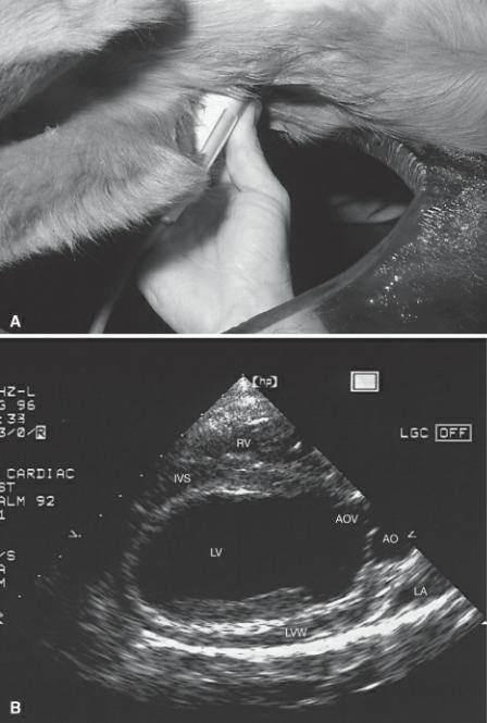
Figure 2.16 (A) This shows the spatial orientation of the sound plane for the right parasternal longaxis left ventricular outflow view of the heart. The heart is positioned as seen from above the animal while the animal is in right lateral recumbency. The transducer is placed under the animal on the right side of the thorax, and the plane transects the heart along its length from right side to left side and base to apex. (B) An illustration of the cardiac structures seen in this plane is shown. The image is displayed on the monitor so that the top of the sector corresponds to the skin surface and transducer location. (C) The two-dimensional image of this plane through the heart during systole. (D) The twodimensional image of this plane through the heart during diastole. R = reference mark, T = transducer, RV = right ventricle, TV = tricuspid valve, RA = right atrium, AO = aorta, AOV = aortic valve, IVS = interventricular septum, LV = left ventricle, MV = mitral valve, LA = left atrium, LVW = left ventricular wall, RMPA = right main pulmonary artery.

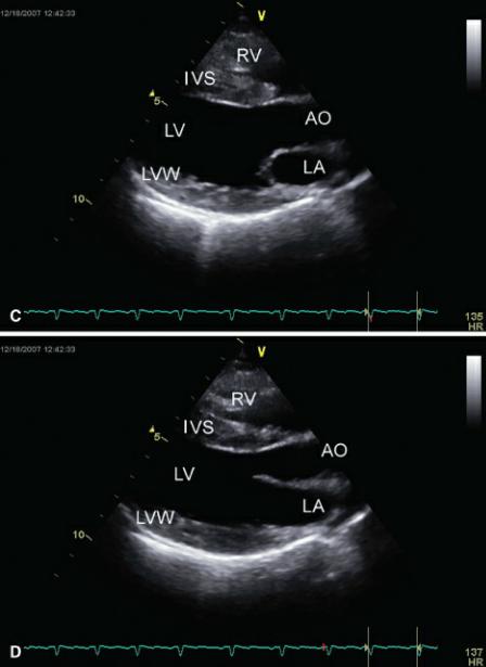
The IVS and anterior aortic wall are continuous in this plane through the heart. The membranous portion of the IVS is seen where the muscular septum becomes a thin white line just proximal to the aorta. The aortic valve cusps seen just to the right of this junction are curved semilunar lines concave to the aorta (Figure 2.17). The anterior (septal) mitral valve (MV) leaflet extends into the left ventricular chamber and is a continuation of the posterior aortic wall. The shorter mural (posterior) MV cusp is at the junction of the muscular LVW and thin left atrial wall (Figure 2.16). A small circular structure that may be seen at the base of the left atrium is a transverse section of the right pulmonary artery.
Figure 2.17 (A) The semilunar cusps of the aortic valve during diastole are clearly seen in this longaxis image of the aorta in a horse. (B) The valve cusps (arrows) are pushed against the walls of the aorta during systole as blood flows past them. RV = right ventricle, RA = right atrium, AO = aorta, AOV = aortic valve, IVS = interventricular septum, LV = left ventricle, LA = left atrium.

The left ventricular wall and portions of the left atrium might not be seen in the horse depending upon the size of the horse, the depth capabilities of the equipment, and the available transducers (Figure 2.18). The mural leaflet of the mitral valve is also often not in the image. Left parasternal imaging is then necessary in order to see these structures.
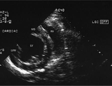
Figure 2.18 The right parasternal long-axis left ventricular outflow view in a horse. RV = right ventricle, RA = right atrium, AO = aorta, AOV = aortic valve, IVS = interventricular septum, LV = left ventricle, LA = left atrium, LVW = left ventricular wall.

Tipped or somewhat apical long-axis views are also generated from this side of the thorax. The same structures are visible, but the apex of the heart is seen toward the top left of the sector image while the atria are seen to the bottom right (Figures 2.19, 2.20).
Figure 2.19 This is the right parasternal tipped (apex up) long-axis left ventricular outflow view in a dog. RV = right ventricle, RA = right atrium, AO = aorta, VS = interventricular septum, LV = left ventricle, MV = mitral valve, LA = left atrium, LVW = left ventricular wall.
Figure 2.20 The right parasternal tipped long-axis left ventricular outflow view in a horse. RV = right ventricle, AO = aorta, AOV = aortic valve, IVS = interventricular septum, LV = left ventricle, MV = mitral valve, LA = left atrium, LVW = left ventricular wall.

An outflow image that optimizes the aorta, the aortic valve, and the left ventricular outflow tract can be obtained by slight movement of the transducer away from the inflow outflow view. The mitral valve and left atrium are not seen well in this imaging plane, and the free wall papillary muscle is usually prominent, but all other structures remain the same (Figure 2.21).
Figure 2.21 Dropping the transducer away from the thorax slightly brings the aortic valve cusps (arrows) clearly into view. RV = right ventricle, AO = aorta, VS = interventricular septum, LV = left ventricle, LVW = left ventricular wall, PM = papillary muscle.
Scanning Technique: Small Animal
This long-axis plane through the heart is obtained by placing the transducer within the 3rd to 6th intercostal space. It is generally placed more cranial in deep-chested and small dogs than in larger dogs. The transducer is usually quite close to the sternum in cats and small dogs, but in larger dogs,

transducer placement is farther away from the sternum toward the costochondral junction. Do not be afraid to move the transducer once an image is found. Most animals have several echocardiographic “windows”; look for the one with the best resolution.
Small Animal
Right Parasternal Long Axis
Left Ventricular Outflow View
Imaging Technique
Use the 3rd to 6th intercostal space.
The transducer is close to the sternum in cats and small dogs but farther away from the sternum in larger dogs. The reference mark is toward the neck.
Point the crystals toward the lumbar spine. Cable extends toward the elbow.
There is about a 45° angle between the transducer and the animal.
The reference mark of the transducer should be directed toward the scapular-humoral joint of the shoulder, and the transducer face (crystals) should be pointed dorsally and caudally toward the animal’s lumbar spine. There should be an angle of approximately 45° between the transducer and the table. The sound plane should follow an imaginary line extending from the scapular-humoral joint to the xiphoid (Figures 2.22, 2.23). It helps to hold the transducer in the following manner while searching for the heart (Figure 2.23): cradle it in your hand with an index finger over the reference mark, which is oriented along the plane of the scapula, the cable extended toward the elbows, the crystals directed toward the lumbar vertebrae, and the transducer tilted at about 45° to the table. Starting in a 3rd or 4th intercostal space, slide the transducer dorsal and ventral in the space from the costochondral junction to the sternum. If a clear image of the heart is not obtained, move caudal an intercostal space. Slide dorsal and ventral in this intercostal space (ICS) and in each ICS until a clear image of the heart is seen. Do not stop at locations that show a poor quality heart. Remember not to lift, drop, or rotate the transducer while searching for the best “window,” and when a good resolution image is found, the imaging plane will be very close to a good long axis of the heart. Then twist into a longer ventricular chamber if necessary, fan the transducer up to the thorax or down away from it to bring in the heart base and widen the left ventricular chamber. For individuals that want to feel for a point of maximal intensity (PMI) as a starting point, place the transducer in an intercostal space cranial to the PMI for correct image orientation on the sector.
Figure 2.22 The long axis of the dog’s heart is aligned from approximately shoulder to xiphoid. The transducer face and sound plane should be aligned along an imaginary line connecting the base of the heart to the apex.

Figure 2.23 The right parasternal long axis with left ventricular outflow is obtained by holding the transducer as shown in this image. Cradle the transducer in your hand with the reference mark under the index finger. Hold it with the reference mark directed toward the neck, the cable extended toward the elbows, and the face directed toward the lumbar spine. There should be an angle of approximately 45° between the transducer and the table.
The feline heart is positioned in its thorax so that the long axis is aligned more with the sternum. Because of this, the transducer is located very close to the sternum with an angle between the cat and the transducer that can approach 30° (Figure 2.24). The best images in cats are obtained when the cat is stretched out and the spine is kept straight. Position the transducer on the right side of the sternum far enough cranial that only air is seen on the sector image. Hold the transducer correctly as described for the dog. Slide the transducer caudally along the sternum until the heart comes into view. This may be a beating blob of haze, but slide caudal until the blob is centered. Then slowly slide the transducer dorsally in the intercostal space or ventrally in the space. One way or the other will bring in a clear image of the long axis of the heart. Which direction works (sliding dorsal in the intercostal space or sliding toward the sternum) depends upon how close to the sternum the transducer stayed while sliding caudal. If you move too far away from the sternum as you slide caudal, this process will not
work. Twist to lengthen and fan the transducer up toward the thorax or down away from it slightly to widen the chambers and bring in the heart base well. Once the long-axis left ventricular outflow view is obtained, all movements toward the other views are similar to those described in dogs.
Figure 2.24 The length of the heart in cats is aligned a little more along the sternum, and the transducer face is directed a little more toward the spine in order to obtain the long-axis left ventricular outflow view.
This image should include the aortic root, left ventricular outflow tract, left ventricular chamber, mitral valve, and left atrium. If the image shows an interatrial septum and a short-left ventricle instead of the aorta and a long ventricle (Figure 2.25), rotate the transducer along its long axis in a counterclockwise direction so the reference mark moves away from the spine toward the front legs. When the aorta is visualized, images that do not include a good left atrium and well-defined mitral valve (Figure 2.26) should be adjusted by slowly lifting the probe into a plane more parallel with the exam table. Stop the lifting motion when the mitral valve is clearly seen and moves well. Lifting too much will cause the aorta to disappear and the left ventricular chamber to become small.
Figure 2.25 This image shows the interatrial septum, left atrium, and a short left ventricular chamber. Rotate the transducer counterclockwise, so the reference mark moves toward the front legs, to lengthen the left ventricle and bring in the aorta. Make sure to keep the mitral valve moving. If its motion is not detectable, you have let the transducer drop away from the thorax a little. Lift it back up until the mitral valve leaflets move well again and continue the rotation until the left ventricular chamber is long and wide. RA = right atrium, RV = right ventricle, TV = tricuspid valve, LA = left atrium, LV = left ventricle, IVS = interventricular septum, IAS = interatrial septum, LVW = left ventricular wall, MV = mitral valve.
Figure 2.26 This image shows good length to the left ventricle and aorta, but the left atrium and mitral valve are not seen well. Lift the transducer up toward the dog into a plane more parallel with the exam table in order to bring the left atrium and mitral valve into view. RV = right ventricle, LV = left ventricle, IVS = interventricular septum, AOV = aortic valve, AO = aorta, LVW = left ventricular wall, LA = left atrium.
Often a long-axis image shows all the correct structures but is foreshortened with no length to the left ventricular chamber (Figure 2.27). There can be several reasons for this. Usually it is because the sound plane does not cut through the ventricular long axis (Figure 2.27). When this is the case, rotating the transducer about its axis in a clockwise or counterclockwise direction will lengthen the left ventricle. Sometimes, the plane of sound may not be pointed back toward the lumbar spine enough to line up with the length of the heart. Imagine a dog’s heart on a lateral radiograph. The base of the
heart is up toward the shoulder and the apex is down toward the sternum. The plane of sound should be directed along the imaginary line connecting these two reference points following the length of the heart (Figure 2.22) and not cranial and caudal in line with the spine. Then, even if the sound plane is directed along the length of the aorta correctly, it may not be traveling through the middle of the heart. Fanning the transducer up toward the table or down away from it will correct the image if this is the reason. Any or all three of these reasons may be a factor. Change one thing at a time, and after creating the best image with each movement then change another thing. If the image becomes worse with any movement reverse the movement and try another one. Each movement should be done slowly because the adjustments are usually very slight. When none of the above transducer movements works, the reason is usually that the transducer is not positioned under the heart properly. Move the probe within the intercostal space toward the spine or toward the sternum until a larger ventricular chamber is seen and try all of the above motions again.
Figure 2.27 (A) This image shows all the structures seen in a right parasternal long-axis left ventricular outflow view of the heart, but there is no length to the ventricular chamber. The sound plane may not be directed through the length of the ventricle. (B) Here the transducer is rotated too far clockwise while in (C) the transducer is rotated too far counterclockwise. Either way the sound plane slices through the top or bottom of the heart instead of through the middle. Rotate clockwise or counterclockwise in order to improve the plane. RV = right ventricle, RA = right atrium, AO = aorta, LV = left ventricle, IVS = interventricular septum, LVW = left ventricular wall, LA = left atrium.

Once a long axis of the left ventricle is obtained, the image can be fine tuned. Resolution is sometimes improved by simply applying a little more pressure. Circling is a technique that involves sliding the transducer in a 360° circle around the spot it is in. This allows the sound beam to be positioned in the intercostal space where it creates the best image resolution. Do not pivot the transducer 360°; nothing should change about how the transducer is positioned relative to the chest wall, just its location changes. Circling involves sliding over the chest wall along each side of the intercostal space. In imaging planes where the angle between the transducer and chest wall is small, a transducer position on the rib allows the sound beam to enter the intercostal space without bone interference and can result in great image quality.
The image can be manipulated in order to see more of the ventricles or more of the heart base. Without changing anything else, point the crystals more dorsal toward the spine and away from the hip, while the cable moves away from the animal’s front legs toward the sternum (Figure 2.28). More of the atria and aorta will be seen as these structures move into the center of the sector image.

Alternately, directing the transducer crystals more caudal, toward the hip, as the cable moves away from the sternum toward the head, allows the left and right ventricles to move into the center of the sector image (Figure 2.29).
Figure 2.28 (A) Pointing the transducer toward the spine and away from the hips will bring the base of the heart into the center of the sector image. (B) The aorta and left atrium are seen in the center of the image, and only a portion of the left ventricle will be seen. RV = right ventricle, IVS = interventricular septum, LV = left ventricle, AO = aorta, LVW = left ventricular wall, MV = mitral valve, LA = left atrium.
Figure 2.29 (A) Pointing the transducer face toward the apex of the heart will bring the apex of the left ventricle toward the center of the image while the base of the heart moves out of the image to the right. (B) More of the left ventricular chamber is seen when this is done, and very little of the base of the heart is seen in the image. RV = right ventricle, IVS = interventricular septum, LV = left ventricle, AO = aorta, AOV = aortic valve, LA = left atrium, LVW = left ventricular wall.
When the apex of the heart is seen toward the upper left side of the image while the base of the heart is seen at the lower right side of the image, the image is called a tipped long axis. This image can be used to subjectively evaluate the cardiac structures but a more horizontally oriented imaging plane provides better alignment for M-mode. A tipped long-axis imaging plane means the transducer is located too far caudal on the chest wall, near the apex of the heart (since the apex is up near the top of the sector image).
To get a more horizontal displayed left ventricular image, move the transducer into a more cranial intercostal space and move dorsal in that intercostal space toward the costochondral junction to stay under the heart base. Point the crystals caudal and move the cable toward the head away from the legs to generate a left ventricular image with good length (Figure 2.30). Rotate the transducer about its long axis, clockwise or counterclockwise, in order to keep the aorta in view after moving into this position.
Figure 2.30 The transducer needs to move cranially one intercostal space, slide dorsally within that space, and the face should be directed caudally in order to align the long-axis left parasternal images

more horizontally across the sector image. If the aorta disappears or the left ventricle becomes smaller, rotate the transducer one way or the other.
Scanning Technique: Horse
Place the transducer within the 3rd to 5th intercostal space, about 2 to 3 inches dorsal to the olecranon. Start with the transducer at a right angle (perpendicular) to the thoracic wall. The reference mark of the transducer should be dorsal and slightly cranial, about 1 o’clock when looking down the length of the transducer (Figure 2.31). The transducer should be pushed cranial into the horse’s leg until a clear cardiac image is obtained. This requires some effort; the usual cause of poor image quality is because the transducer is not located far enough forward. Hold the transducer perpendicular to the thoracic wall, as you slide it forward. Do not point the crystals forward. If the leg is not positioned cranially and abducted slightly, it will require a lot of work to obtain a clear image. Slide the transducer dorsal or ventral in the intercostal space, keeping it perpendicular to the chest wall (don’t point up or down) if sliding forward does not result in a clear image of the left ventricle. Remember to keep the transducer perpendicular to the chest wall. At this point, the image may lack a good aorta and have a foreshortened left ventricular chamber (Figure 2.32). In order to bring the aorta, or more of the aorta, into view, rotate the transducer clockwise towards 1 or 2 o’clock until most of the ascending aorta comes into view. Don’t worry about what is happening to the ventricle or mitral valves at this time, just rotate until a long aorta is seen. Keep the transducer perpendicular to the thorax; don’t point the crystals forward while rotating. Once a good aorta is seen, but the mitral valve and left atrium are not seen well (Figure 2.32), improve the image by holding the transducer in the same place (this can be done by using your other hand to keep the probe from sliding caudal on the thorax) and point the crystals slightly caudal (Figure 2.32). This will move the cable of the transducer toward the horse’s leg. Often it feels as though the cable cannot be pushed into the leg any further when an adequate image is obtained. Don’t rotate, just point. The transducer will no longer be perpendicular to the thorax at this time.
Large Animal
Right Parasternal Long Axis
Left Ventricular Outflow View
Imaging Technique
Use the 3rd to 5th intercostal space.

Locate about 2 to 3 inches above the olecranon. Keep the transducer perpendicular to the chest wall. The reference mark is directed toward 1 o’clock.
Push the cable end of the transducer into the leg so crystals point slightly caudal in order to lengthen the LV and bring in the MV. Rotate the transducer so the reference mark moves toward the leg to keep the aorta in the image if necessary.
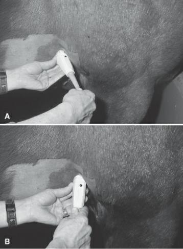
Figure 2.31 Right parasternal long-axis left ventricular outflow views of the horse’s heart are obtained in the 3rd to 5th intercostal space. The reference mark should be directed toward 1 o’clock, the transducer should be pushed forward into the leg, and the face is directed slightly caudal.
Figure 2.32 (A) This long-axis image in a horse lacks an aorta and has a severely foreshortened left ventricular chamber. Rotate the transducer clockwise until a long aorta is seen. (B) When the aorta is clearly seen but the mitral valve is not, lengthen the left ventricular chamber and bring the MV into view by holding the transducer face in the same location with the left hand, and pushing the cable toward the leg in order to direct the face caudally and slightly dorsal without moving on the skin surface. RV = right ventricle, RA = right atrium, IVS = interventricular septum, LV = left ventricle, LVW = left ventricular wall, AO = aorta, AOV = aortic valve, LA = left atrium, MV = mitral valve.

Depending upon how ventrally or dorsally the transducer is placed on the thoracic wall, the image may be a tipped long axis with aorta or it may be the standard long-axis image where the septum and anterior aortic wall run horizontally across the sector image from right to left. A tipped long axis is obtained when the transducer is positioned ventrally on the thorax. The apex of the heart is up toward the top left side of the sector indicating that the probe is positioned closer to the apex of the heart. If the transducer is perpendicular to the thorax and pointed directly into the chest, slide the transducer cranially and dorsally (into the leg and up) in order to see a horizontal orientation on the sector image of the standard long axis with outflow tract view. This moves the probe up toward the base of the heart. Try not to lose the image as you slide the transducer over the skin surface. For both of these movements if the ventricle becomes short again but the aorta is still seen, direct the crystals in a slightly more caudal direction (cable pushed into the leg) to lengthen the chamber. Make sure the reference mark is still at 1 to 2 o’clock. Pointing the crystals toward the base of the heart (up toward 1 o’clock) when a standard long axis with outflow is seen, will bring more of the heart base structures
into view, and pointing the crystals toward the apex (down toward 7 o’clock) brings more of the ventricle into view.
Four-Chamber View
The Image
A slight change in transducer orientation brings the right parasternal four-chamber plane of the heart into view (Figure 2.33). The tricuspid valve and right atrium are generally seen better in this plane than in the left ventricular outflow plane. The RV and RA at the top of the sector are separated by the tricuspid valve. A clear interatrial septum (IAS) is seen on the right side of the image separating the right atrium on top of the sector image from the left atrium at the bottom right of the sector image. The left ventricle and interventricular septum are seen on the left side of the image.
Figure 2.33 (A) The spatial orientation of the sound plane for the right parasternal long-axis fourchamber view of the heart is shown. The heart is positioned as seen from above the animal while the animal is in right lateral recumbency. The transducer is placed under the animal on the right side of the thorax, and the plane spans the heart along its length from right side to left side and base to apex. (B) This illustration of the resulting two-dimensional image shows the relative positions of the cardiac structures. The top of the sector corresponds to the skin surface and transducer location. (C) This is the two-dimensional image of the four-chamber plane through the heart. R = reference mark, T = transducer, RV = right ventricle, TV = tricuspid valve, RA = right atrium, IVS = interventricular septum, LV = left ventricle, MV = mitral valve, LA = left atrium, LVW = left ventricular wall, P = pericardium.

The IAS and IVS are continuous with each other. The mitral and tricuspid valves are positioned at the junction of the IVS and IAS. Typically the tricuspid valve annulus is located very slightly more toward the apex than the mitral valve.
The entire left atrium and free wall of the left ventricle may not be seen in horses (Figure 2.34). Compared to the left ventricular outflow view however, more of the mitral valve and left atrium are usually seen. Tipped four-chamber views show the same structures from a slightly different angle in both the small and large animal (Figures 2.35, 2.36).
Figure 2.34 The right parasternal long-axis four-chamber view in a horse. Portions of the left ventricular wall and left atrium may not be seen in large horses. RV = right ventricle, TV = tricuspid valve, RA = right atrium, IVS = interventricular septum, LV = left ventricle, MV = mitral valve, LA = left atrium, LVW = left ventricular wall.
Figure 2.35 This is the right parasternal tipped long-axis four-chamber view in a dog. RV = right ventricle, TV = tricuspid valve, RA = right atrium, IVS = interventricular septum, LV = left ventricle, MV = mitral valve, LA = left atrium, LVW = left ventricular wall, CT = chordae tendinae, P = pericardium.
Figure 2.36 This is the right parasternal tipped long-axis four-chamber view in a horse. RV = right ventricle, TV = tricuspid valve, RA = right atrium, VS = interventricular septum, LV = left ventricle, MV = mitral valve, LA = left atrium, LVW = left ventricular wall.

Scanning Technique: Small Animal
Parasternal four-chamber images of the heart are obtained by rotating the reference mark of the transducer toward the spine past the shoulder after the left ventricular outflow plane through the heart is seen (Figure 2.37). It helps to keep the mitral valve in view and moving well while twisting to a four-chamber view. If valve motion is reduced, stop rotating and lift or drop the transducer to improve valve motion and then continue the twisting until a four-chamber view is reached. Once the aorta has disappeared and the atrial septum is in view, rock the transducer up toward the table or down away from it in order to maximize left ventricular size.
Small Animal
Right Parasternal Long Axis
Four-Chamber View
Imaging Technique
Start with the left ventricular outflow view.
Rotate the reference mark toward the spine until the aorta disappears.
Lift and drop the transducer until left ventricular size is maximized.
Point the crystals more caudal if the LV is still too short.
Figure 2.37 Parasternal long-axis four-chamber views of the heart are obtained by (A) leaving the transducer in the same location as for the left ventricular outflow view and (B) rotating the transducer clockwise until the reference mark is directed more toward the spine. As you rotate, do not lose the mitral motion. If you do, it means the transducer has dropped away from the thorax. Stop the rotation, lift the transducer back up making the angle between the transducer and thorax smaller until the valve leaflets move well again, and then continue the rotation.

Scanning Technique: Equine
Starting at the right parasternal long axis with left ventricular outflow view, rotate the transducer counter-clockwise so that the reference mark moves toward 12 o’clock (Figure 2.38). Continue to rotate the transducer until the aorta has disappeared and an interatrial septum is seen. Keep the crystals pointed slightly caudal with the cable pushed into the leg in order to keep length to the left ventricular chamber. This motion toward the four-chamber plane works from both the tipped long axis and the standard long-axis view of the heart.
Large Animal
Right Parasternal Long Axis
Four-Chamber View
Imaging Technique
Remain in the same location as for the left ventricular outflow view.
Rotate the transducer counterclockwise until the reference mark is at about 12 o’clock.
Keep the cable pushed into the leg for a long LV.
Figure 2.38 (A) Rotate the transducer counterclockwise until the reference mark is directed toward 12 o’clock in order to see the right parasternal four-chamber view of the heart. The cable should still be pushed into the leg and the transducer face is directed slightly caudal in order to keep length to the left ventricle. (B) Pointing the face dorsal will produce a tipped four-chamber view of the heart.
Right Parasternal Short-Axis Images
Introduction
Transverse images of the heart may be obtained at any level from the base to the apex. Five standard images are taken in the transverse plane: the left ventricle, the chordae tendinae, the mitral valve, the heart base with aorta, and the high heart base with pulmonary artery (Figure 2.39). In the small animal an additional angled view through the long axis of the pulmonary artery with an oblique view of the left ventricle is also presented here. This plane is between the longitudinal and short axis. As with the right parasternal long-axis views of the heart, these transverse or short-axis planes are very similar in both large and small animals.
Figure 2.39 There are five standard transverse images of the heart. All are obtained from the same transducer location on the right side of the thorax. The transducer is pivoted from apex to base (caudal and ventral to cranial and dorsal) in order to obtain these views. (A) The left ventricle with papillary muscles, (B) left ventricle at chordae tendinae, (C) left ventricle at mitral valve, (D) heart base— aorta, (E) heart base—pulmonary artery. R = reference mark.

Transverse or short-axis images of the heart in small animals are obtained by rotating the transducer toward the sternum with the reference mark turned 90° from its location for the long-axis plane. The mark is generally directed toward the animal’s elbow. The same place on the thorax is used for transverse and long-axis images. The transducer is held a little more perpendicular (about 60°) with respect to the exam table for transverse images and is pivoted from the base of the heart to the apex in order to obtain the various short-axis planes (Figure 2.40). The cable is still directed ventrally since it is not held perpendicular to the thoracic wall and the fanning motion is done with this 45° to 60° angle in mind. Depending upon how the transducer is being held, any of the transverse planes can be viewed first. As you point the transducer toward the apex of the heart, the crystals should be directed toward the xiphoid and the cable should extend cranially (Figure 2.40). As you point the crystals toward the base of the heart (the shoulder), the cable should move toward the xiphoid (Figure 2.40). The fanning motion for scanning from base to apex should follow the length of the heart along an imaginary line extending from the shoulder to xiphoid (Figure 2.22). These motions sound extreme but in actuality are very slight. A small arc at the thoracic wall creates a large arc deep within the thorax. At each imaging plane, rotate the transducer clockwise or counterclockwise as necessary to create a true transverse imaging plane.
Figure 2.40 (A) The left ventricular transverse view is obtained by rotating the transducer until the reference mark is directed toward the elbow or sternum and tilting the transducer slightly caudal and ventral. Stop rotating when a circular symmetrical left ventricle is seen. The cable should be directed slightly cranial. Because the transducer is not perpendicular to the thoracic wall for these images, the cable should still extend ventrally toward the sternum or elbow. (B) The transducer is pivoted and directed cranially and dorsally toward the shoulder in order to obtain the transverse mitral valve image. The cable should extend down and ventrally toward the xiphoid. (C) Pivot the transducer even more toward the shoulder in order to obtain the transverse view of the aorta. The cable should extend caudally and ventrally toward the xiphoid. The reference mark is still directed toward the elbows. Rotate the transducer slightly if necessary in order to view the aorta in the transverse circular plane. (D) Once a transverse image of the aorta is obtained, pivot the transducer a little more cranially and dorsally in order to see the pulmonary artery and its bifurcation. Pivot the transducer in a circular motion until the clearest images of the pulmonary artery are seen.

When the sector image shows only part of the short-axis image and the rest is out of the sector to the
left (Figure 2.41), the transducer needs to be lifted up toward the thorax so the crystals point toward the spine creating a smaller angle between the transducer and the chest wall, or physically moved in the intercostal space toward the spine so that it is more directly under the heart. The opposite holds true for images that are partially out of the picture to the right (Figure 2.42). The transducer needs to have a larger angle between it and the chest wall or physically moved toward the sternum.
Figure 2.41 When the heart moves off the sector image to the left side of the monitor, the transducer is located too close to the sternum. Either physically move the transducer in the intercostal space toward the spine or point the transducer face toward the spine by lifting the transducer toward the table. LV = left ventricle, RV = right ventricle, IVS = interventricular septum, LVW = left ventricular wall.
Figure 2.42 When the heart moves off the sector image to the right side of the monitor, the transducer is located too close to the spine. Either physically move the transducer in the intercostal space toward the sternum or point the transducer face toward the sternum. LV = left ventricle, IVS = interventricular septum, LVW = left ventricular wall.

Transverse views of the heart in a horse are obtained by rotating the transducer clockwise toward the olecranon with the reference mark at approximately 4 to 5 o’clock, 90° from its direction in the longaxis plane. The transducer crystals are fanned in dorsal to ventral directions, from base to apex, in order to obtain the various short-axis planes. The heart base is dorsal and cranial at approximately 1 o’clock, and the apex is sternal and caudal at about 7 o’clock.
Left Ventricle with Papillary Muscles and Chordae Tendinae View
The Image
Images toward the apex of the heart at the level of the papillary muscles (Figure 2.43) show a crescent-shaped right ventricular chamber at the top of the sector image. A circular left ventricle is seen below the interventricular septum. Symmetrically shaped papillary muscles are seen within the left ventricular cavity at about the 4- and 9-o’clock positions or the 3- and 8-o’clock positions. The papillary muscle on the left side of the transverse image is the subatrial papillary muscle, while the papillary muscle to the right side of the transverse image is the subauricular papillary muscle (23). The shape of the left ventricular chamber in this plane is often described as a mushroom. Slight fanning of the sheet of sound toward the base of the heart shows chordae tendinae at their attachment points to the papillary muscles (Figure 2.44).
Figure 2.43 (A) The spatial orientation of the sound plane within the heart is shown for the right parasternal short-axis left ventricle with papillary muscles view. The heart is positioned as seen from above the animal while the animal is in right lateral recumbency. The transducer is placed under the animal on the right side of the thorax, and the plane traverses the heart from right side to left side. (B) This illustration of the resulting two-dimensional image shows the relative positions of the cardiac structures. The top of the sector corresponds to the skin surface and transducer location. (C) This is the two-dimensional image of this plane through the heart. R = reference mark, T = transducer, RV = right ventricle, IVS = interventricular septum, LV = left ventricle, LVW = left ventricular wall, PM = papillary muscle, APM and PPM = anterior and posterior papillary muscle, P = pericardium.

Figure 2.44 Slight movement of the transducer toward the base of the heart shows chordae tendinae at their attachment points on the papillary muscles. RV = right ventricle, IVS = interventricular septum, LV = left ventricle, CT = chordae tendinae, LVW = left ventricular wall, P = pericardium.

The free wall of the left ventricle may not be seen in large animals unless the equipment has depth capabilities of greater than 24 cm (Figure 2.45). Images from most normal hearts will fit on a 24-cm depth sector image with the free wall completely visible during systole and only partially visible during diastole. The left ventricular chamber is somewhat more triangular in shape than the left ventricle in dogs and cats.
Figure 2.45 This is the right parasternal short-axis left ventricle with papillary muscles view in a horse. RV = right ventricle, IVS = interventricular septum, LV = left ventricle, LVW = left ventricular wall, PM = papillary muscle.
Scanning Technique: Small Animal
Rotate the transducer until images of the left ventricle show a circular shape with symmetrical papillary muscles. The cable is directed ventral and cranial (Figure 2.40). An egg-shaped ventricle
means the transducer has not been turned enough or it has been turned too much (Figure 2.46). Rotate it back and forth until the most circular shape is seen.
Small Animal
Right Parasternal Short Axis Views
Imaging Technique
Remain in the same spot on the thorax as for the long-axis views.
Rotate the reference mark toward the elbows.
Drop the transducer down away from the animal slightly (about 60° between animal and transducer.
The cable is still directed toward sternum.
Point the crystals from xiphoid to shoulder to get all five transverse images.
Figure 2.46 An egg-shaped left ventricular chamber means the transducer has either been rotated too much or not enough. Rotate it clockwise and counterclockwise until a symmetrical circular chamber is obtained. RV = right ventricle, LV = left ventricle, IVS = interventricular septum, LVW = left ventricular wall, PM = papillary muscle.
The further back toward the apex of the heart the transducer is positioned when obtaining transverse sections the less right ventricle you will see. This usually happens when the starting long-axis plane before twisting to transverse views was a tipped view. Move forward an intercostal space and dorsal in order to direct the sound plane through the middle of the heart and a larger section of the left and right ventricles.
Scanning Technique: Equine
Rotate the transducer clockwise away from the long-axis plane until the reference mark is located at about 4 o’clock (Figure 2.47). The transducer should be almost perpendicular to the thoracic wall with the crystals pointed in a slightly caudal and ventral direction. Rock the transducer in a line joining 7 to 1 o’clock in order to find the largest most symmetrical image for a true transverse plane through the

left ventricle. The left ventricle is a circle, and the papillary muscles should be similar in appearance and size. If one appears to be larger than the other and the chamber is slightly egg shaped, the transducer has been rotated too much or too little.
Large Animal
Right Parasternal Short-Axis Views
Imaging Technique
Remain in the same location as for the long-axis views.
Rotate the transducer until the reference mark is at about 4 o’clock and a circular LV or aorta is seen. Point crystals down to the sternum for the LV and up to the neck for the heart base.
Figure 2.47 (A) Transverse images of the left ventricle are obtained by rotating the transducer toward the olecranon 90° from its location for the long-axis planes at about 4 o’clock. Rotate until a symmetrical circular left ventricular chamber is seen. The face is almost perpendicular to the thorax but may be pointing slightly ventral and caudal. (B) Pivot the transducer face upward so the sound plane is directed a little more dorsally and cranially to see the short-axis view of the mitral valve. The cable will move down toward the floor. (C) Continue pointing the transducer face in a cranial and dorsal direction in order to see the base of the heart with aorta. Rotate the transducer clockwise and counterclockwise if necessary if it is not a closed circular structure, in order to see the aorta in a true transverse section. (D) The face is pointed cranial and dorsal even more in order to image the pulmonary artery. The angle between the transducer and the thoracic wall is quite small by the time this view is obtained. The transducer should be rotated back and forth until clear images of the artery are obtained.

Mitral Valve View
The Image
Pointing the transducer crystals more toward the base of the heart brings the mitral valve into view. The leaflets will appear as an oval within the left ventricular chamber when open and as touching lines when they are closed during systole (Figure 2.48). Movement of the mitral valve in this imaging plane is often referred to as the “fish mouth.” The top leaflet in the fish mouth is the septal leaflet, and the leaflet that lies close to the left ventricular wall is the mural leaflet. A larger portion of the right ventricle can now be seen above the left ventricle at the top of the sector image. Slower heart rates and longer diastolic filling periods in the horse make the mitral valve appear “floppier” than the valve motion appreciated in dogs and cats. Figure 2.49 shows this view in the horse.
Figure 2.48 (A) The spatial orientation of the sound plane within the heart is shown for the right parasternal short-axis left ventricle with mitral valve. The heart is positioned as seen from above the animal while the animal is in right lateral recumbency. The transducer is placed under the animal on the right side of the thorax, and the plane crosses the heart from right side to left side. (B) This illustration of the resulting two-dimensional image shows the relative positions of the cardiac structures. The top of the sector corresponds to the skin surface and transducer location. (C) This is the two-dimensional image of this plane through the heart with a partially open mitral valve. R = reference mark, T = transducer, RV = right ventricle, PM = papillary muscle, VS = interventricular septum, LV = left ventricle, LVW = left ventricular wall, MV = mitral valve, AMV = anterior mitral valve (septal leaflet), PMV = posterior mitral valve (mural leaflet).

Figure 2.49 This is the right parasternal short-axis left ventricle with mitral valve image in a horse. RV = right ventricle, IVS = interventricular septum, LV = left ventricle, AMV = anterior mitral valve leaflet.

Scanning Technique: Small Animal
Fan the transducer very slightly toward the neck. The cable should move toward the xiphoid if the LV was imaged first and away from the xiphoid if the heart base was imaged first (Figure 2.40). At the level of the mitral valve, both leaflets of the valve should be attached to the lateral walls. Rotate the transducer back and forth until a nice symmetrical oval-shaped valve is seen within the left ventricular chamber. This imaging plane is often referred to as the “fish mouth” as it mimics the mouth of a fish seen head on.
Scanning Technique: Equine
The mitral valve is located just above the level of the papillary muscles and should be seen as a very symmetrical oval shape extending across the ventricular chamber. Movement up from the apex of the heart toward the base requires pointing the crystals dorso-cranially (Figure 2.47). Just before the mitral valve is visible, chordae tendinae will be seen at their attachment sites on the papillary muscles. The ventricular chamber should still be circular in shape. If it becomes oval, rotate the transducer clockwise or counterclockwise until it becomes circular again. At the level of the mitral valve, both leaflets of the valve should be attached to the lateral walls. Images that do not show this kind of symmetry require either less or more rotation of the transducer to improve the scan plane.
Heart Base: Aorta and Left Atrium View
The Image
Toward the base of the heart, the aorta is seen as a circle or clover shape in the middle of the sector image (Figures 2.50, 2.51). All three valve cusps are present in this view of the heart. The image of closed valve leaflets in this plane is often called the “Mercedes sign” because of its resemblance to that manufacturer’s logo. The cusp that is located at the junction of the atrial septum is the noncoronary cusp. The cusp located next to the right ventricular chamber is the right coronary cusp, and the cusp positioned just above the left atrium and next to the left auricle is the left coronary cusp
(23,24). Above the aorta, at the top of the sector, as always when transducer placement is on the right side of the thorax, is the right ventricle. The right ventricle extends from approximately 11 o’clock where the tricuspid valve is seen to the right side of the image where the pulmonary artery is. The pulmonary valve if visible on this view may be seen anywhere from 3 to 5 o’clock. In cats this valve is located a little higher on the sector image, closer to the 2- to 3-o-clock location. The main pulmonary artery extends downward from the valves, but only a portion of it is seen since the left auricle, a wedge-shaped extension of the left atrium is seen just below the pulmonary valve. The interatrial septum, seen at the left side of the image, separates the two atria. The shape of the left atrium and auricle has been described as a whale or tadpole with the left auricular appendage representing the tail of the whale or tadpole.
Figure 2.50 (A) The spatial orientation of the sound plane within the heart is shown for the right parasternal short-axis view of the heart base with aorta. The heart is positioned as seen from above the animal while the animal is in right lateral recumbency. The transducer is placed under the animal on the right side of the thorax, and the plane spans the heart from right side to left side. (B) This illustration of the resulting two-dimensional image shows the relative positions of the cardiac structures. The top of the sector corresponds to the skin surface and transducer location. (C) This is the two-dimensional image of this plane through the heart. R = reference mark, T = transducer, RV = right ventricle, RA = right atrium, IAS = interatrial septum, NC, RC, LC = non, right, and left coronary aortic valve cusps, PV = pulmonary valve, LA = left atrium, LAA and LAU = left auricular appendage.

Figure 2.51 The right parasternal short-axis view of the heart base with aorta in a horse shows the aortic valve cusps. RV = right ventricle, RA = right atrium, IAS = interatrial septum, NC, RC, LC = non, right, and left coronary aortic valve cusps, LA = left atrium, PA = pulmonary artery.

Coronary arteries can be seen leaving the sinus of Valsalva if the transducer is tilted and rotated slightly at the level of the aortic valves. The left coronary artery can be seen near the junction of the aorta, left auricle, and pulmonary artery (Figure 2.52). The right coronary artery may be seen coming from the area of the right coronary cusp above the pulmonary valve to the top right side of the sector image. Slight rotation of the transducer allows both cross-sectional and longitudinal images of the arteries to be seen (Figure 2.53).
Figure 2.52 A transverse view of a coronary artery in the right parasternal short-axis view of the heart base with aorta in a horse. RV = right ventricle, RA = right atrium, TV = tricuspid valve, PV = pulmonic valve, PA = pulmonary artery, AO = aorta, C = coronary artery.
Figure 2.53 This transverse plane through the heart base in a horse shows a sagittal view of a coronary artery as it leaves the aorta. RV = right ventricle, AO = aorta, LA = left atrium, C = coronary artery.

Scanning Technique: Small Animal
Point the transducer crystals even more toward the neck (heart base), and the aorta will appear in the middle of the image. The cable now extends toward the xiphoid (Figure 2.40). Fan and twist the transducer back and forth until all three aortic valve cusps are seen. If the interatrial septum and the left auricle are not seen clearly, twist the transducer so the reference mark moves a little more to the sternum. At this point there is often air interference in the image. Try to clean up the image by slowly sliding the transducer around the intercostal space (circling as described earlier). At times the transducer needs to move forward an intercostal space to improve the image. When you move the transducer forward, be sure to move dorsally toward the spine (heart base) at the same time.
Scanning Technique: Equine
Continue pointing the crystals up toward the base of the heart in a dorsal and cranial direction (Figure 2.47). A clover-shaped aorta will appear in the center of the image. The crystals should be pointed dorsally and cranially toward about 1 o’clock and the reference mark, typically located anywhere from 4 to 5 o’clock, should be rotated clockwise and counterclockwise until all three aortic valve cusps are seen.
Heart Base: Pulmonary Artery View
The Image
Slightly further toward the base of the heart is the fifth plane, which shows the pulmonary artery in its length up to and including its bifurcation into the right and left main pulmonary arteries (Figures 2.54, 2.55). The pulmonary valve is located to the right of the image anywhere from 2 to 4 o’clock. Only a small portion of the LA is now visible between the right atrium and right pulmonary artery branch at about 8 and 9 o’clock on the image. The bifurcation is usually seen between 5 and 6 o’clock on the sector. The right main pulmonary artery extends from right to left under the ascending aorta. The left
main pulmonary artery however is just barely seen past the bifurcation as it extends into the lung field.
Figure 2.54 (A) The spatial orientation of the sound plane within the heart is shown for the right parasternal short-axis view of the heart base with pulmonary artery. The heart is positioned as seen from above while the animal is in right lateral recumbency. The transducer is placed under the animal on the right side of the thorax, and the plane traverses the heart from right side to left side. (B) This illustration of the resulting two-dimensional image shows the relative positions of the cardiac structures. The top of the sector corresponds to the skin surface and transducer location. (C) This is the two-dimensional image of this plane through the heart. R = reference mark, T = transducer, RV = right ventricle, RA = right atrium, TV = tricuspid valve, IAS = interatrial septum, PA = pulmonary artery, PV = pulmonic valve, RMPA = right main pulmonary artery, LMPA = left main pulmonary artery, AO = aorta, LA = left atrium.

Figure 2.55 The right parasternal shortaxis view of the heart base with pulmonary artery in a horse. PV = pulmonary valve, PA = pulmonary artery, RMPA and LMPA = right and left main pulmonary artery, RA = right atrium, AO = aorta.
Scanning Technique: Small Animal
Once a good image of the heart base with aorta, left atrium, and left auricle is seen, the crystals are tilted just a little more toward the heart base in order to bring the main pulmonary artery into view (Figure 2.40). The rest of the image may not be clear but the pulmonary valve and the bifurcation should be. Clearer images of the pulmonary artery and valve may require sliding a little ventral and moving the transducer back onto the rib just caudal to the transducer. This allows the sound beam to enter the ICS better (given the sharp angle of transducer and chest wall) and will usually improve image quality allowing the entire main pulmonary artery and its bifurcation to be seen.
Scanning Technique: Equine
Clear images of the pulmonary artery and valve require pointing the crystals slightly more dorsal and cranial toward 1 o’clock and fanning the crystals right and left (cranial and caudal) once the heart base is seen in order to create the best possible image of the pulmonary artery (Figure 2.47). Rotate the transducer clockwise and counterclockwise as necessary in order to see the valves distinctly.
Left Ventricle with Pulmonary Artery View
The Image
This oblique right parasternal image is generated at the level of the left ventricle. Slight dropping of the transducer allows us to see the pulmonary artery running along the right side of the image next to an egg-shaped left ventricle (Figure 2.56). Long’s right parasternal angled view in the horse is a modification of this plane (Figure 2.57) (9). This image shows not only the pulmonary valve at about

4 to 5 o’clock, but also the right ventricular outflow above it and the main pulmonary artery segment below it. The pulmonary artery bifurcation is typically not seen in this plane.
Figure 2.56 An oblique right parasternal view of the left ventricle shows the main pulmonary artery and pulmonary valve. RV = right ventricle, PA = pulmonary artery, PV = pulmonary valve, LV = left ventricle.
Figure 2.57 This is the left ventricle with pulmonary artery in the horse. RV = right ventricle, PA = pulmonary artery, PV = pulmonary valve, LV = left ventricle.
Scanning Technique: Small Animal
Start with a tipped right parasternal long-axis left ventricular outflow view. A tipped view is obtained by moving the transducer closer to the apex of the heart and pointing the crystals slightly cranial in order to direct the crystals along the length of the heart and toward the heart base. From this plane,

drop the transducer down, away from the table into a more vertical position, until the mitral valve is no longer in view, but the aorta and left ventricle are still clearly visible. No rotation of the transducer should have occurred and the ventricle should not have lost its length (Figure 2.58). The pulmonary artery will be seen on the right side of the sector image and the left ventricle will be egg shaped. Once the artery is seen, point the transducer in slightly different cranial directions and from side to side until the longest pulmonary artery is seen.
Small Animal
Right Parasternal Oblique Axis
Left Ventricle with Pulmonary Artery
Imaging Technique
Start with the tipped long-axis left ventricular outflow view.
Drop the transducer away from the animal until the mitral valve doesn’t move, but the aorta and its valve is still clearly seen.
Rotate the reference mark toward the sternum.
Stop when the pulmonary artery is seen on the right side of the image.
Point the crystals in different directions until the longest pulmonary artery is seen.
Figure 2.58 Starting with (A) the left ventricular outflow view, (B) tilt the transducer down away from the dog until the mitral valves are not seen moving anymore. At that point rotate the transducer counterclockwise toward the sternum until the pulmonary artery comes into view along the right side of the sector.
Left Parasternal Apical Images
Introduction
True apical images of the heart are a challenge to obtain and often what appears to be a true left ventricular apex is really part of the left ventricular lateral wall. Nevertheless, these images are used for many two-dimensional quantitative studies of function and are excellent planes for Doppler interrogation of the mitral, tricuspid, and aortic valves. These views in the horse are severely foreshortened since depth and anatomical restrictions make true apical images impossible to obtain.
Apical Five-Chamber View
The Image
The apical five-chamber long-axis image is generated with the transducer placed near the apex of the heart close to the sternum. The sound plane is directed dorsally and cranially along the length of the heart (Figure 2.59). The apex of the LV is seen at the top right side of the image. The LA is seen at the bottom right side of the image with the mitral valve opening up into the left ventricular chamber. On the left side of the image, the RV is seen at the top of the sector and the RA at the bottom of the image and the tricuspid valve between them. Between the two atria is a longitudinal view of the aorta as it leaves the left ventricle in a downward direction.
Figure 2.59 (A) The spatial orientation of the sound plane within the heart is shown for the apical five-chamber view of the heart obtained from a left parasternal caudal transducer location. The heart is positioned as seen from above the animal while the animal is in left lateral recumbency. The transducer is placed on the left side of the thorax under the animal, and the plane crosses the heart from apex to base. (B) This illustration of the resulting two-dimensional image shows the relative positions of the cardiac structures. The top of the sector corresponds to the skin surface and transducer location. (C) This is the two-dimensional image of this plane through the heart. R = reference mark, T = transducer, RV = right ventricle, RA = right atrium, TV = tricuspid valve, LA = left atrium, LV = left ventricle, IVS = interventricular septum, AO = aorta, MV = mitral valve, AOV = aortic valve.

Despite a severely foreshortened left ventricle at the top of the sector image in the horse, the left atrium is seen at the bottom right side of the image with the mitral valve opening upward into the left ventricle just like in the dog and cat (Figure 2.60). The aorta is located centrally and extends downward on the image. This imaging plane is described and labeled by Long as the left parasternal angled view with left ventricular outflow and aorta (9).
Figure 2.60 The left parasternal apical five-chamber view in a horse. The ventricles are severely foreshortened. LA = left atrium, LV = left ventricle, IVS = interventricular septum, AO = aorta, MV = mitral valve, AOV = aortic valve.

Scanning Technique: Small Animal
Transducer positions for the apical fiveand four-chamber views in the small animal are very similar, and they will be discussed together after the description of the apical four-chamber view.
Scanning Technique: Equine
Move the transducer to a more ventral position on the thoracic wall than is required for the horizontal four-chamber view. The reference mark needs to be directed to approximately 1 or 2 o’clock (Figure 2.61). The transducer is angled dramatically for this image as the crystals are directed in a cranial and dorsal direction. Rock the transducer toward the body and away from the body until clear images of the mitral valve and aortic root are seen. The aorta will be located centrally in the image while the left atrium and mitral valves are to the right.
Large Animal
Left Parasternal Apical View
Five-Chamber View
Imaging Technique
Slide the transducer down to just above the level of the olecranon and caudal a couple of intercostal spaces from where the parasternal fourand five-chamber views were obtained.
The reference mark is at 2 to 3 o’clock.
The crystals are directed cranial and dorsal toward 10 or 11 o’clock. There is a small angle between the transducer and thorax (less than 30°).
Fan and circle the transducer toward the thorax and away from it until clear images are seen.
Figure 2.61 To obtain the left parasternal apical five-chamber view of the heart in a horse the reference mark needs to be located at approximately 1 to 2 o’clock. The transducer is sharply angled with the face directed cranially and dorsally from a ventral location on the thoracic wall. Placement should be near the level of the elbow. Pivot the transducer toward and away from the body until the clearest images are obtained.

Apical Four-Chamber View
The Image
Remaining in the same intercostal space near the apex of the heart, sight movement of the transducer allows visualization of much more of the right side of the heart as the apical four-chamber plane is seen (Figure 2.62). The aorta is no longer seen, instead the interatrial septum is now located between the left and right atria. The mitral and tricuspid valves are seen at the junction of the IAS and the IVS. They open upward into the ventricles.
Figure 2.62 (A) The spatial orientation of the sound plane within the heart is shown for the apical four-chamber view of the heart obtained from a left parasternal caudal transducer location. The heart is positioned as seen from above the animal while the animal is in left lateral recumbency. The transducer is placed on the left side of the thorax under the animal, and the plane spans the heart from apex to base. (B) This illustration of the resulting two-dimensional image shows the relative positions of the cardiac structures. The top of the sector corresponds to the skin surface and transducer location. (C) This is the two-dimensional image of this plane through the heart. R = reference mark, T = transducer, RV = right ventricle, RA = right atrium, TV = tricuspid valve, IVS = interventricular septum, IAS interatrial septum, LA = left atrium, LV = left ventricle, MV = mitral valve.

Scanning Technique: Small Animal
The reference mark should be directed dorsally and caudally with the crystals directed cranially toward the shoulder and base of the heart (Figure 2.63). The transducer should be placed as close to the apex of the heart as possible. Often it is easiest to start in one of the last intercostal spaces near the xiphoid and find the liver. Move cranial along the sternum space by space until the heart is seen. If only the ventricular chambers are seen, lift the transducer into a more horizontal position while still pointing the crystals toward the shoulders in order to bring the heart base into the image. The transducer can be quite parallel to the body in narrow-chested animals. If the image is not clear, first slide the probe dorsally in the space and then if it is still not clear, move forward one more space. More pressure is applied to the transducer for these images than for any other since the probe is so parallel to the body wall and effort is needed to direct the sound beams between the ribs. Remember to

circle into the best window within that intercostal space.
Small Animal
Left Parasternal Apical Views
Imaging Technique
The reference mark is dorsal and caudal toward the lumbar spine. The sound plane is parallel with the table.
The crystals are pointed toward the neck. The cable extends toward the knees.
Start with the liver and move forward along the sternum until the heart is seen. Move away from sternum, dorsally, if the image is not clear.
Lift the transducer up toward the animal for the five-chamber view, drop it down for the four-chamber view.
Figure 2.63 (A) With the reference mark directed dorsally and caudally and the face directed toward the shoulder and base of the heart, a four-chamber view of the heart is imaged. A transducer angle of less than 30° from the body wall is common. (B) Tilt the transducer up toward the body wall in order to bring the aorta into view and obtain the apical five-chamber plane through the heart. Rotate the transducer back and forth slightly when moving from one plane to the next in order to maximize left atrial size and mitral valve motion.
One of the two apical planes should be visible at this point. A four-chamber view is seen if the transducer is not parallel enough to the body wall (Figure 2.63). Lift the transducer up toward the thorax and the aorta will come into view for the five-chamber imaging plane (Figure 2.63).
Conversely if the five-chamber view is visible, drop the transducer away from the body wall (cable goes down) and the four-chamber view will appear. Rotate the transducer slightly, moving the reference mark down away from the animal’s body when imaging from fiveto four-chamber planes in order to maintain ventricular length, get both atria in the image, and to get the best mitral valve motion.
When the apex of the heart is not at the top of the sector image but off to the right side (Figure 2.64), the crystals are directed toward the spine too much and need to be redirected toward the heart base. Point the crystals more toward the shoulder and front legs. The movement should involve sweeping the crystals in an arc without changing the sound plane with respect to the body, from the spine, toward the head and legs. The transducer usually also needs to slide ventrally toward the sternum and caudal a little. This movement will bring the length of the ventricle into view as well as move the apex of the heart to the top of the sector image. In cats the transducer is usually aligned more parallel to the length of the body than in the dog, and the angle between the transducer and the body wall is small enough that the transducer often hugs the body wall (Figure 2.65).
Figure 2.64 When the apex of the heart is located to the right side of the image (arrow) instead of at the top of the sector, the transducer face is directed too much toward the spine when it should be pointed more toward the head and legs. LV = left ventricle, RV = right ventricle, IVS = interventricular septum, AO = aorta, LA = left atrium, MV = mitral valve.
Figure 2.65 The transducer is aligned very parallel with the body of a cat in order to obtain apical views.

Left Parasternal Cranial Long-Axis Images
Introduction
The first three left parasternal long-axis views described here are found in small animals from a cranial position on the left side of the thorax. Only slight manipulation of the transducer is required in order to move from one plane to the next.
The last two left parasternal long-axis views described in this section are found in the large animal. These two planes are similar to the right parasternal left ventricular outflow and four-chamber longaxis views except the left side is seen at the top of the sector image and the right side is seen at the bottom of the sector image. Although not described by the Echocardiography Committee, these imaging planes can also be found in dogs and cats.
Directions for the left-sided views are presented as movements away from the left parasternal long axis with left ventricular outflow view. Pay particular attention to obtaining good images for that view and the others will come easily. Directions are given for small animals placed in left lateral recumbency and imaged from below through a cutout in the table.
Left Cranial Left Ventricular Outflow View
The Image
The left parasternal left ventricular outflow view is the reference plane for this side of the thorax. This image is obtained from a very cranial transducer position and looks very similar to the right parasternal long-axis left ventricular inflow outflow view except that the tricuspid valve is not seen (Figure 2.66). Instead, the pulmonary valve is seen above the ascending aorta. This view is excellent for observing the aortic valve and ascending aorta. Images still maintain the base of the heart to the right and apex to the left orientation.
Figure 2.66 (A) The spatial orientation of the sound plane within the heart is shown for the left parasternal long-axis left ventricular outflow view in a dog. The heart is positioned as seen from above the animal while the animal is in left lateral recumbency. The transducer is placed cranially on the left side of the thorax below the animal. The plane transects the heart from base to apex and left to right. (B) This illustration of the resulting two-dimensional image shows the relative positions of the cardiac structures. The top of the sector corresponds to the skin surface and transducer location. (C)

This is the two-dimensional image of this plane through the heart. R = reference mark, T = transducer, RV = right ventricle, PV = pulmonic valve, IVS = interventricular septum, LA = left atrium, LV = left ventricle, MV = mitral valve, AO = aorta, AOV = aortic valve, LVW = left ventricular wall.
Scanning Technique: Small Animal
The left 3rd to 4th intercostal spaces are used for this image. Directing the reference mark cranially, the transducer face and sound beam should almost line up along the long axis of the body with the crystals pointing toward the spine and slightly caudal. The cable will extend out from the sternum and since the crystals are pointed slightly caudal, the cable is extending slightly cranial toward the elbows (Figure 2.67). The transducer has an angle of approximately 45° with respect to the chest wall. Move the transducer dorsal and cranial until a clear image is obtained. These cranial images show the heart base, and your hand is usually touching the front leg if you are under the heart base (dorsal and cranial

enough). Then pivot the transducer up toward the table and down away from it until the left ventricular outflow tract is seen. Rotate the transducer until the aorta is as long and wide as it can be.
Small Animal
Left Parasternal Cranial Long Axis
Left Ventricular Outflow View
Imaging Technique
Use the 3rd to 4th intercostal space, your hand should be touching the front leg.
The reference mark is cranial.
There is about a 45° angle between the transducer and the thorax.
The crystals are directed slightly caudal toward the thoracic spine.
The cable extends toward the elbows.
The transducer is 2 to 3 inches away from the sternum.
Figure 2.67 (A) With the transducer very cranial in the left 3rd or 4th intercostal space, the reference mark directed cranially and the sound plane directed along the length of the body the left parasternal long-axis left ventricular outflow view is obtained. The transducer is lifted up toward the table and down away from the table until the aorta is seen and will generally be held at about a 30° angle away from the exam table. (B) Without changing transducer location, drop the transducer down away from the thoracic wall and the right atrium and auricle will come into view. (C) Lifting the transducer toward the thoracic wall away from the left ventricular outflow view will bring the right ventricular outflow tract and pulmonary artery into the image. (D) The pulmonary artery can be centered more within the image by lifting the transducer a little more and pointing the face more caudal.

Left Cranial Right Atrium and Auricle View
The Image
Remaining in the cranial location and pivoting the beam slightly results in a plane that transects the right atrium, tricuspid valve, and right auricle (Figure 2.68). This image provides an oblique view of both ventricles, with an egg-shaped left ventricle on the left side of the image and the right ventricle on the top right of the sector image. The tricuspid valve opens upward toward the right ventricle and the right atrial appendage extends to the right and up from the atrium. The caudal vena cava (CVC) may be seen as it enters the right atrium from the left side of the image.
Figure 2.68 (A) The spatial orientation of the sound plane within the heart is shown for the left parasternal long-axis right atrium and auricle view in a dog. The heart is positioned as seen from above the animal while the animal is in left lateral recumbency. The transducer is placed cranially on the left side of the thorax below the animal. (B) This illustration of the resulting two-dimensional image shows the relative positions of the cardiac structures. The top of the sector corresponds to the skin surface and transducer location. (C) The two-dimensional image of this plane through the heart looks like this. R = reference mark, T = transducer, RV = right ventricle, RA = right atrium, RAU = right auricle, TV = tricuspid valve, IVS = interventricular septum, LV = left ventricle.

Scanning Technique: Small Animal
Without changing the location, position, or sound beam direction, drop the cable end of the transducer down away from the exam table in order to bring the right atrium and auricle into view (Figure 2.67). Lift and drop the transducer until the largest and clearest right auricle, atrium, and tricuspid valves are seen. The clearest and largest views of the right auricle may not show the best tricuspid valve motion. Rotate the transducer clockwise and counterclockwise to obtain clear images of the tricuspid valve. This may be at the expense of clear auricular images.
Small Animal
Left Parasternal Cranial Long Axis
Right Atrium and Auricle

Imaging Technique
Remain in the same location as for the left ventricular outflow view.
Drop the transducer down away from the animal.
Left Cranial Right Ventricular Outflow View
The Image
The third plane to be generated from the left cranial transducer position also requires slight fanning away from the left ventricular outflow plane. The right ventricular outflow tract and pulmonary valve are seen along the top and right of the image, with an oblique left ventricle and atrium along the bottom (Figure 2.69). The pulmonary artery extends downward from the valve along the right side of the image. A small piece of the aortic valve may be seen at the junction of the left ventricle and pulmonary artery. Slight manipulation of this view gives a more vertical plane through the pulmonary artery (Figure 2.70). Other structures are often not clear in this more vertical image, but the pulmonary valve is imaged well, and this image provides excellent alignment with flow for Doppler interrogation.
Figure 2.69 (A) The spatial orientation of the sound plane within the heart is shown for the left parasternal long-axis right ventricular outflow view in a dog. The heart is positioned as seen from above the animal while the animal is in left lateral recumbency. The transducer is placed cranially on the left side of the thorax below the animal. (B) This illustration of the resulting two-dimensional image shows the relative positions of the cardiac structures. The top of the sector corresponds to the skin surface and transducer location. (C) The two-dimensional image of this plane through the heart. R = reference mark, T = transducer, RV = right ventricle, PA = pulmonary artery, RMPA = right main pulmonary artery, LMPA = left main pulmonary artery, LV = left ventricle, LVW = left ventricular wall, PV = pulmonic valve, MV = mitral valve, AOV = aortic valve, LA = left atrium.

Figure 2.70 Slight modification of the left ventricular outflow view allows the pulmonary to be located centrally and more vertically in the image. PA = pulmonary artery, PV = pulmonic valve, RV = right ventricle, VS = ventricular septum, LV = left ventricle, MV = mitral valve, LA = left atrium.

Scanning Technique: Small Animal
From the transducer position used for the left parasternal long-axis left ventricular outflow view, the cable end of the transducer is lifted up toward the scan table. It will be almost parallel with the table for this plane (Figure 2.67). As the transducer is raised up, the left ventricular outflow tract will disappear from view, and the pulmonic valve and right ventricular outflow tact will be seen to the right of the sector image. More of the left atrium is seen and only a glimpse of the aortic valve is seen if it is seen at all. Fan the transducer up and down slightly until the clearest pulmonary valve is seen. Slight rotation of the transducer in a clockwise or counterclockwise direction and circling the transducer a little can bring more of the pulmonary artery into view at the expense of other structures, which will lose their definition (Figure 2.67).
Small Animal
Left Parasternal Cranial Long Axis
Right Ventricular Outflow View
Imaging Technique
Remain in the same location as for the left ventricular outflow view.
Lift the transducer up toward the animal.
Left Cranial Four-Chamber View: Equine
The Image
This four-chamber view of the heart is obtained in the horse from a cranial location on the left side. It has the left ventricular chamber on the left side of the image and the left atrium on the right of the image (Figure 2.71). The left ventricular free wall is seen at the top of the sector image while the interventricular septum is seen below the left ventricular chamber. This plane through the heart offers a better look at the left ventricular free wall as well as the left atrium and mitral valve, which are often not completely seen on right parasternal images. A more horizontal image can also be obtained

(Figure 2.72).
Figure 2.71 This is a tipped left parasternal four chamber view of the heart in a horse. LV = left ventricle, LVW = left ventricular wall, LA = left atrium, MV = mitral valve, IVS = interventricular septum, RA = right atrium, RV = right ventricle.
Figure 2.72 The transducer has been moved to a more dorsal and cranial location on the left side of the horse in order to obtain this more horizontally positioned four-chamber view of the heart. LV = left ventricle, LVW = left ventricular wall, LA = left atrium, MV = mitral valve, IVS = interventricular septum, RA = right atrium, RV = right ventricle.
Scanning Technique: Equine
This is the reference view for imaging from the left side. Long refers to this view as the left ventricular inlet view (9). Transducer movement to all other planes is referenced from this view. The horse’s leg should be abducted and pulled forward. Transducer placement is in the left 4th to 5th intercostal space about 2 to 3 inches above the olecranon (Figure 2.73). The reference mark should be straight up toward the spine at 12 o’clock, the transducer should be almost perpendicular to the chest wall, but point the transducer cranial and dorsal slightly until the longest and widest left ventricular chamber is seen. The mitral valve should open well and chordae tendinae should be seen. As with the long-axis planes on the right side, the starting location determines whether a tipped view or a more horizontal view is seen. If the view is tipped, it is because the transducer has been placed in a more ventral and caudal location so that the apex is nearer to the transducer than the base. Point the crystals cranially and dorsally from the tipped view in order to see the left atrium and mitral valve well. Rotate the transducer about its axis until the best view of the left atrium is obtained. Slide the transducer up on the thorax toward the spine and forward a space to change a tipped view into a more horizontal image.
Large Animal
Left Parasternal Long Axis
Four-Chamber View
Imaging Technique
Use the 4th to 5th intercostal space.
Locate 2 to 3 inches above the level of the olecranon.
The reference mark is at 12 o’clock.
Keep the transducer almost perpendicular to the thoracic wall.
Point the crystals dorsal and cranial until the largest LV is seen.
Figure 2.73 The left parasternal long-axis images of the heart in a horse are obtained from the 4th or 5th intercostal space just dorsal to the olecranon. The reference mark is directed straight up at 12 o’clock, and the face is pointed slightly cranial and dorsal until the longest left ventricular chamber is seen. Pivot the transducer cranial and caudal to lengthen the left ventricle.
Left Cranial Five-Chamber View (Large Animal)

The Image
This image is a modification of the four-chamber parasternal long-axis view just described, and now the aorta is included in the image (Figure 2.74). Portions of the right ventricle and atrium are seen below the ventricular septum.
Figure 2.74 The tipped left parasternal five chamber view of the heart in a horse includes the aorta. LV = left ventricle, LVW = left ventricular wall, LA = left atrium, MV = mitral valve, IVS = interventricular septum, AO = aorta, AOV = aortic valve, RA = right atrium, RV = right ventricle, TV = tricuspid valve.
Scanning Technique: Equine
Slide the transducer ventrally and caudally from the four-chamber view. Point the crystals cranial and dorsal in order to keep the left atrium and mitral valves in the image. Rock the transducer toward the body and away from the body until clear images of the mitral valves and aortic root are seen. The transducer is almost flat against the chest wall in some horses (Figure 2.75). Rotate the transducer slightly if necessary to bring in the aorta. The reference mark will be at approximately 11 o’clock on the thorax.
Large Animal
Left Parasternal Long Axis
Five-Chamber View
Imaging Technique
Remain in the same location as for the four-chamber view.
Rotate the transducer counterclockwise until the aorta is seen; the reference mark should be at about 10 or 11 o’clock.
Figure 2.75 Once the tipped left parasternal long-axis four-chamber image of the heart is obtained,

rotate the transducer clockwise until the aorta comes into view. The reference mark will be located at about 10 or 11 o’clock.
Left Parasternal Short-Axis Images
Introduction
These transverse images can be obtained in both the large and small animal. Structures are the same as those seen in the right parasternal images but have different locations.
Left Cranial Transverse Heart Base View
The Image
Remaining in the left 4th or 5th intercostal space but twisting the transducer toward a transverse plane through the heart creates the left parasternal short-axis view of the base of the heart (Figure 2.76). The aorta is still seen as a circle or clover-shaped structure in the center of the image. The right atrium is at the left side of the image, and the right ventricle wraps over the top of the aorta. The tricuspid valve is found at about 8 to 9 o’clock. On the right side of the image the pulmonary artery curves around the aorta as it does in right parasternal images but the pulmonary valve is located at about 12 to 1 o’clock. The image can be manipulated to show a better tricuspid valve at the expense of the pulmonary artery by pointing the transducer face caudal a bit. The image may also be adjusted to see a better pulmonary artery and valve at the expense of the tricuspid valve by pointing the transducer face cranial a little. The bifurcation of the main pulmonary artery into its branches is seen in this imaging plane. This is a good plane for Doppler evaluation of the pulmonary artery and tricuspid valve. Tricuspid valve regurgitation is often aligned well in this imaging plane for Doppler interrogation. In the horse a plane very similar to this is described and labeled by Long as the left parasternal angled view through the right ventricular inlet and outlet (Figure 2.77) (9).
Figure 2.76 (A) The spatial orientation of the sound plane within the heart is shown for the left parasternal short-axis view of the heart base. The heart is positioned as seen from above the animal while the animal is in left lateral recumbency. The transducer is placed under the animal on the left side of the thorax and the plane spans the heart from left side to right side. (B) This illustration of the resulting two-dimensional image shows the relative positions of the cardiac structures. The top of the

sector corresponds to the skin surface and transducer location. (C) This shows the two-dimensional image of this plane through the heart. R = reference mark, T = transducer, RV = right ventricle, RA = right atrium, TV = tricuspid valve, IAS = interatrial septum, PV = pulmonary valve, PA = pulmonary artery, RMPA and LMPA = right and left main pulmonary artery, AO = aorta, RC, NC, and LC = right, non, and left coronary cusp, LA = left atrium, P = pericardium.
Figure 2.77 The real time two-dimensional left parasternal oblique view of the heart in a horse shows well-defined pulmonary and tricuspid valve. RV = right ventricle, RA = right atrium, TV = tricuspid valve, PV = pulmonary valve, PA = pulmonary artery, AO = aorta, C = coronary artery.

Scanning Technique: Small Animal
Staying in the same place on the thorax as for the cranial long-axis views, twist the transducer until the reference mark is directed to the spine and down away from the thorax, about 90° from its location for imaging the cranial long-axis images. The transducer should have an angle of about 70 to 80° with respect to the animal’s thorax, the cable end of the transducer extending to the sternum (Figure 2.78). Rotate the transducer until the aorta is a circle in the center of the image. Drop the transducer away from the body wall a little during rotation. Pointing the crystals cranial will bring in the pulmonary valve and artery to the right side of the sector image. The pulmonary artery bifurcation is seen well in this imaging plane. Pointing the crystals caudal a little will bring the tricuspid valve and right atrium into view on the left side of the aorta. The more cranial the transducer is placed on the thorax the better the right atrium and tricuspid valve will be. The tricuspid valve will open almost straight up toward the top of the sector in these images.
Small Animal
Left Parasternal Short Axis
Heart Base
Imaging Technique
Remain in the same location as for the cranial long-axis images.
Rotate the transducer until the reference mark is toward the thoracic spine and pointing down away from the thorax.
Drop the transducer down away from the animal until it is about 70° from the thorax.
If the aorta is not a circle, rotate the transducer clockwise and counterclockwise until it is. If that doesn’t work, move forward or back a space.
Figure 2.78 The reference mark should be directed dorsally and the transducer should be held almost perpendicular to the dog at about 70 to 80° away from the chest in order to obtain the left parasternal short-axis view. The cable should extend very slightly ventral and caudal, and the face is typically directed slightly cranial.

Scanning Technique: Equine
The transducer must be located as far cranial and dorsal as possible (Figure 2.79). When the left front leg is pulled as far forward as possible, this view is easier to get. Once the base of the heart is seen, point the crystals caudal and dorsal in order to image the pulmonary artery, its valve, the tricuspid valve, and right atrium as they wrap around the left side of the image. The reference mark on the transducer should be located at approximately 1 or 2 o’clock. Circle in all directions until the best images are obtained.
Large Animal
Left Parasternal Short Axis
Heart Base
Imaging Technique
Slide as far cranial and dorsal as possible into the front leg.
Locate reference mark at 12 to 1 o’clock.
Point the crystals caudal and slightly dorsal until both pulmonic and tricuspid valves are seen.
Figure 2.79 (A) Place the transducer as far forward as possible at the level of the olecranon in order to obtain the left parasternal short axis view of the heart base. The reference mark is at 12 to 1 o’clock and the face is directed slightly caudal and dorsal. (B) Here the transducer is pulled away from the leg in order to better show how the sound plane is oriented.

Left Cranial Left Auricle View: Small Animal
The Image
An imaging plane found between the pulmonary artery and the right atrium on the previous imaging plane allows the left auricle to be seen. More of the auricular appendage is seen from this imaging plane than from the right parasternal transverse view of the left atrium. In dogs the auricle extends along the right side of the image, curving around the aorta up to about 11 o’clock on the sector image. In cats the tip of the auricle often extends around the top of the sector to about 12 or 11 o’clock (Figure 2.80).
Figure 2.80 This image of the left auricular appendage is obtained from a left cranial transducer position. RV = right ventricle, LAA = left auricular appendage, LA = left atrium, AO = aorta, RA = right atrium.

Scanning Technique: Small Animal
The left auricle is seen while fanning the transducer between the pulmonary valve and the tricuspid valve in the transverse left cranial imaging plane. Slowly fan between the two valves, keeping the aorta in the image, and the left auricle is located on the right side of the image. Rotate and circle the transducer a little to optimize imaging of this structure. In dogs the tip of the auricular appendage is located at about 1 o’clock, while in cats it often extends to 12 or 11 o’clock on the sector image.
Small Animal
Left Cranial Transverse View
Left Auricle
Imaging Technique
Locate at the same place as the left transverse heart base with aorta.
Fan the crystals cranial and caudal between the right atrium and pulmonary artery levels.
The left auricle is seen between these two planes.
Left Cranial Transverse Left Ventricle View: Equine
The Image
The left ventricle is seen at the top right of the sector image. One papillary muscle may be lost within the near field at the top of the sector while the other papillary muscle is located at about 4 to 5 o’clock on the sector image (Figure 2.81). The interventricular septum separates the triangular-shaped left ventricular chamber from the crescent-shaped right ventricular chamber. This imaging plane in the small animal provides great views of the right ventricular wall. The right ventricular wall may not be seen in the horse because of depth limitations.
Figure 2.81 This two-dimensional left parasternal transverse section of the left ventricle shows the left ventricular wall at the top of the sector image. LV = left ventricle, LVW = left ventricular wall, IVS = interventricular septum, RV = right ventricle, RVW = right ventricular wall.

Scanning Technique: Equine
Starting with the left parasternal long-axis four-chamber horizontal view, rotate the transducer until the left ventricle is seen as a circular structure at the top of the sector image. Keep the transducer perpendicular to the chest wall. The reference mark will be located at approximately 3 to 4 o’clock on the thorax (Figure 2.82). The papillary muscles should be very equal in size, and the left ventricular chamber should not be oblong if the transducer has been rotated enough. Pivot the transducer face slightly in every direction until the size of the left ventricular chamber is maximized.
Large Animal
Left Parasternal Short Axis
Left Ventricle
Imaging Technique
Start with the four-chamber view.
Rotate the transducer until the reference mark is at 3 to 4 o’clock and a circular left ventricle is seen.
Pivot transducer about its location in multiple directions to find the largest symmetrical LV chamber.
Figure 2.82 To obtain the left parasternal transverse left ventricular view (A) start with the long axis. (B) Rotate the transducer clockwise until the reference mark is located at approximately 3 or 4 o’clock. Rotate back and forth until the left ventricle is circular with symmetrical papillary muscles. The transducer face should be pivoted cranially and caudally until the left ventricular chamber size is maximized.

Subcostal Image
Subcostal Five-Chamber View: Small Animal
The Image
This subcostal imaging plane shows the same structures that the parasternal apical five-chamber imaging plane does. Imaging from a subcostal location aligns the ascending aorta more parallel with a Doppler cursor allowing more accurate analysis of aortic flow (Figure 2.83). The liver is seen at the top of the sector image and the apex of the left ventricular chamber is just below the liver lobe.
Figure 2.83 This subcostal apical five-chamber view is obtained through the liver. GB = gall bladder, LV = left ventricle, AOv = aortic valve, AO = aorta.
Scanning Technique: Small Animal
This imaging plane can be done while the animal is in either right or left lateral recumbency. Position the transducer under the xiphoid with the reference mark pointing toward the spine. The crystals are pointed straight through the liver toward the animal’s head. The transducer should be held very parallel to the abdominal wall (Figure 2.84). Fan the crystals right and left until a clear image is obtained. Rotate the transducer until the aorta is seen. This image usually requires a low frequency transducer.
Small Animal
Subcostal View
Apical Five-Chamber View
Imaging Technique
Place transducer caudal to the xiphoid.
Locate reference mark to animal’s right side.
Place transducer parallel and flat against the body wall.
Figure 2.84 With the reference mark pointing into the abdomen or slightly upward, the crystals are directed through the liver to the apex of the heart. The transducer is usually very parallel with the abdominal wall. The arrow is pointing at the side opposite the reference mark.