

6. System Clock and Clock Options
6.1Clock Systems and their Distribution
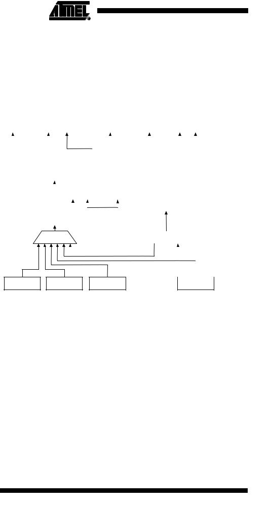
Figure 6-1 presents the principal clock systems in the AVR and their distribution. All of the clocks need not be active at a given time. In order to reduce power consumption, the clocks to modules not being used can be halted by using different sleep modes, as described in ”Power Management and Sleep Modes” on page 32. The clock systems are detailed below.
Figure 6-1. |
Clock Distribution |
|
|
|
|
|
|
|
|
|
|
|
|
|
|
|
|
|
|
|
|
|
|
|
|
|
|
|||||||||||
|
|
ADC |
|
|
|
|
General I/O |
|
|
|
|
|
|
|
|
|
CPU Core |
|
|
|
RAM |
|
|
|
Flash and |
|
||||||||||||
|
|
|
|
|
|
|
Modules |
|
|
|
|
|
|
|
|
|
|
|
|
|
|
|
EEPROM |
|
||||||||||||||
|
|
|
|
|
|
|
|
|
|
|
|
|
|
|
|
|
|
|
|
|
|
|
|
|
|
|
|
|
|
|
|
|||||||
|
|
|
|
|
|
|
|
|
|
|
|
|
|
|
|
|
|
|
|
|
|
|
|
|
|
|
|
|
|
|
|
|
|
|
|
|
|
|
|
|
|
|
|
|
|
|
|
|
|
|
|
|
|
|
|
clkPCK |
|
|
|
|
|
|
|
|
|
|
|
|
|
|
|
|
|
||||
|
|
|
|
|
|
|
|
|
|
|
|
|
|
|
|
|
|
|
|
|
|
|
|
|
|
|
|
|
|
|
|
|
|
|||||
|
|
|
|
|
|
|
|
|
|
|
|
|
|
|
|
|
|
|
|
|
|
|
|
|
|
|
|
|
|
|
|
|
|
|||||
|
|
|
|
|
|
|
|
|
|
|
|
|
|
|
|
|
|
|
|
|
|
|
|
|
|
|
|
|
|
|
|
|
|
|
|
|
|
|
|
|
|
|
|
|
|
|
|
|
|
|
|
|
|
|
|
|
|
|
|
|
|
|
|
|
|
|
|
|
|
|
|
|
|
|
|
||
|
|
|
clkI/O |
|
|
|
AVR Clock |
|
|
|
|
clkCPU |
|
|
|
|
|
|
|
|
|
|
|
|
|
|
|
|
|
|||||||||
|
|
|
|
|
|
|
|
|
Control Unit |
|
|
|
|
|
|
|
|
|
|
|
|
|
|
|
|
|
|
|
|
|
|
|
|
|
|
|||
|
|
|
|
|
|
|
|
|
|
|
|
|
|
|
|
|
|
|
|
|
|
|
|
|
|
|
|
|
|
|
|
|
|
|
|
|
|
|
|
|
|
|
|
|
|
|
|
|
|
|
|
|
|
|
clkFLASH |
|
|
|
|
|
|
|
|
|
|
|
|
|
|
|
|
|
|||||
|
|
|
clk |
ADC |
|
|
|
|
|
|
|
|
|
|
|
|
|
|
|
|
|
|
|
|
|
|
|
|
|
|
|
|
||||||
|
|
|
|
|
|
|
|
|
|
|
|
|
|
|
|
|
|
|
|
|
|
|
|
|
|
|
|
|
|
|
|
|
|
|
||||
|
|
|
|
|
|
|
|
|
|
|
|
|
|
|
|
|
|
|
|
|
|
|
|
|
|
|
|
|
|
|
|
|
|
|
||||
|
|
|
|
|
|
|
|
|
|
|
|
|
Reset Logic |
|
Watchdog Timer |
|
|
|
|
|
|
|
|
|
|
|
|
|
||||||||||
|
|
|
|
|
|
Source clock |
|
|
|
|
|
|
|
|
|
|
|
|
|
|
|
|
|
|
|
|
|
|
|
|
|
|
|
|
||||
|
|
|
|
|
|
|
|
|
|
|
|
|
|
|
|
|
|
|
|
|
|
|
|
|
|
|
|
|
|
|
|
|
|
|||||
|
|
|
|
|
|
|
|
|
|
|
|
|
|
|
|
|
|
|
|
|
|
|
|
|
|
|
|
|
|
|
|
|
|
|
|
|||
|
|
|
|
|
|
|
|
|
|
|
|
|
|
|
|
|
|
|
|
|
|
|
|
|
|
|
|
|
|
|
|
|
||||||
|
|
|
|
|
|
|
|
|
|
|
|
|
|
|
|
|
Watchdog clock |
|
|
|
|
|
|
|
|
|
|
|
|
|
|
|||||||
|
|
|
|
|
|
|
|
|
System Clock |
|
|
|
|
|
|
|
|
|
|
|
|
PCK |
|
|
||||||||||||||
|
|
|
|
|
|
|
|
|
|
|
|
|
|
|
|
|
|
|
|
|
|
|
|
|
|
|
|
|
|
|
||||||||
|
|
|
|
|
|
|
|
|
Prescaler |
|
|
|
|
|
|
|
|
|
|
|
|
|
|
|
|
|
|
|
|
|
|
|||||||
|
|
|
|
|
|
|
|
|
|
|
|
|
|
|
|
|
|
|
|
|
|
|
|
|
|
|
|
|
|
|
|
clk |
|
|
||||
|
|
|
|
|
|
|
|
|
|
|
|
|
|
|
|
|
|
|
|
|
|
|
|
|
|
|
|
|
|
|
|
|
|
|||||
|
|
|
|
|
|
|
|
|
|
|
|
|
|
|
|
|
|
|
|
|
|
|
|
|
|
|
|
|
|
|
|
|
||||||
|
|
|
|
|
|
|
|
|
|
Clock |
|
|
|
|
|
|
|
|
|
Watchdog |
|
|
|
|
|
PLL |
|
|
|
|||||||||
|
|
|
|
|
|
|
|
|
Multiplexer |
|
|
|
|
|
|
|
|
|
Oscillator |
|
|
|
|
|
Oscillator |
|
|
|
||||||||||
|
|
|
|
|
|
|
|
|
|
|
|
|
|
|
|
|
|
|
|
|
|
|
|
|
|
|
|
|
|
|
|
|
|
|
|
|
|
|
|
|
|
|
|
|
|
|
|
|
|
|
|
|
|
|
|
|
|
|
|
|
|
|
|
|
|
|
|
|
|
|
|
|
|
|
|
|
|
|
|
|
|
|
|
|
|
|
|
|
|
|
|
|
|
|
|
|
|
|
|
|
|
|
|
|
|
|
|
|
|
|
|
|
|
|
|
|
|
|
|
|
|
|
|
|
|
|
|
|
|
|
|
|
|
|
|
|
|
|
|
|
|
|
|
|
|
|
|
|
|
|
|
|
|
|
|
|
|
|
|
|
|
|
|
|
|
|
|
|
|
|
|
|
|
|
|
|
|
|
|
|
|
|
|
|
|
|
|
|
|
|
|
|
|
|
External Clock |
CalibratedCrystal RC |
Low-Frequency |
Calibrated RC |
|
Oscillator |
Crystal Oscillator |
Oscillator |
||
|
6.1.1CPU Clock – clkCPU
The CPU clock is routed to parts of the system concerned with operation of the AVR core. Examples of such modules are the General Purpose Register File, the Status Register and the Data memory holding the Stack Pointer. Halting the CPU clock inhibits the core from performing general operations and calculations.
6.1.2I/O Clock – clkI/O
The I/O clock is used by the majority of the I/O modules, like Timer/Counter. The I/O clock is also used by the External Interrupt module, but note that some external interrupts are detected by asynchronous logic, allowing such interrupts to be detected even if the I/O clock is halted.
6.1.3Flash Clock – clkFLASH
The Flash clock controls operation of the Flash interface. The Flash clock is usually active simultaneously with the CPU clock.
6.1.4ADC Clock – clkADC
The ADC is provided with a dedicated clock domain. This allows halting the CPU and I/O clocks in order to reduce noise generated by digital circuitry. This gives more accurate ADC conversion results.
22 ATtiny25/45/85
2586A–AVR–02/05
ATtiny25/45/85
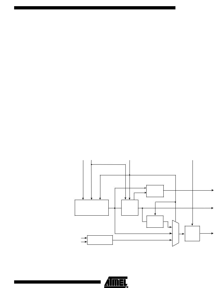
6.1.5Internal PLL for Fast Peripheral Clock Generation - clkPCK
The internal PLL in ATtiny25/45/85 generates a clock frequency that is 8x multiplied from a source input. The source of the PLL input clock is the output of the internal RC oscillator having a frequency of 8.0 MHz. Thus the output of the PLL, the fast peripheral clock is 64 MHz. The fast peripheral clock, or a clock prescaled from that, can be selected as the clock source for Timer/Counter1. See the Figure 6-2 on page 23.
Since the ATtiny25/45/85 device is a migration path for ATtiny15, there is an ATtiny15 compatibility mode for supporting the backward compatibility with ATtiny15. The ATtiny15 compatibility mode is selected by programming the CKSEL fuses to ‘0011’. In the ATtiny15 compatibility mode the frequency of the internal RC oscillator is calibrated down to 6.4 MHz and the multiplication factor of the PLL is set to 4x. With these adjustments the clocking system is ATtiny15 compatible and the resulting fast peripheral clock has a frequency of 25.6 MHz (same as in ATtiny15).
The PLL is locked on the RC oscillator and adjusting the RC oscillator via OSCCAL register will adjust the fast peripheral clock at the same time. However, even if the RC oscillator is taken to a higher frequency than 8 MHz, the fast peripheral clock frequency saturates at 85 MHz (worst case) and remains oscillating at the maximum frequency. It should be noted that the PLL in this case is not locked any longer with the RC oscillator clock.
Therefore, it is recommended not to take the OSCCAL adjustments to a higher frequency than 8 MHz in order to keep the PLL in the correct operating range. The internal PLL is enabled only when the PLLE bit in the register PLLCSR is set or the PLLCK fuse is programmed (‘0’). The bit PLOCK from the register PLLCSR is set when PLL is locked.
Both internal RC oscillator and PLL are switched off in power down and stand-by sleep modes.
Figure 6-2. PCK Clocking System
OSCCAL PLLE |
PLLCK & CKSEL FUSES |
CLKPS3..0 |
|
Lock |
|
PLOCK |
|
Detector |
|
|
RC OSCILLATOR |
PLL |
|
PCK |
8.0 MHz / 6.4 MHz |
8x / 4x |
64 / 25.6 MHz |
|
|
|
||
|
DIVIDE |
|
|
|
BY 4 |
|
|
|
|
System |
SYSTEM |
|
|
CLOCK |
|
|
|
Clock |
|
XTAL1 |
|
Prescaler |
|
OSCILLATORS |
|
|
|
XTAL2 |
|
|
|
23
2586A–AVR–02/05