

- •Contents
- •Introduction
- •Introduction
- •Important Upgrade Information
- •About EOS
- •Graphic User Interface
- •Sequencer and Data Filer
- •Sound Libraries
- •Sound Storage
- •Advanced DSP
- •Built-in Digital Effects
- •More Digital Processing Features
- •Power Up!
- •Loading a Bank from the Hard Disk
- •Loading SoundSprints
- •Selecting Presets
- •Lock Button
- •Saving
- •Arpeggiator
- •Keyboard Modes
- •Whole
- •Layer
- •Split
- •Multi
- •The Basics
- •How Sounds are Organized
- •The Sample
- •Voices
- •The Preset
- •SoundSprint
- •Bookmarks
- •The Bank
- •Folders
- •The Internal Drive
- •To Update the EOS Software:
- •External Drives
- •Sample Memory & Preset Memory
- •Sound ROM & Sound RAM
- •Five Types of Memory
- •Flash Sound RAM
- •Sample Numbers
- •Using Preset Flash Memory
- •Using Sound Flash Memory
- •Modules
- •Saving
- •Default
- •Icons
- •The Cursor
- •Data Entry Control & Increment/Decrement Buttons
- •Selecting
- •Using The Browser
- •Guided Tours
- •Banks, Sequences, Presets & Samples
- •Loading a Bank Automatically
- •Loading a Sequence from a Different Bank
- •Loading Standard MIDI Files
- •Saving Banks
- •Finding Banks, Presets, Samples & Sequences
- •Naming Banks
- •Erasing Banks
- •Assignable Keys
- •Recording a Sequence
- •Arpeggiator Sequencing!
- •A Practice Sampling Session
- •Exploring the Preset
- •Which Voices are Assigned to the Keyboard?
- •Creating a Link
- •Master Menu
- •Overview
- •Memory Statistics
- •Master Utilities
- •Assignable Keys
- •Channel Volume
- •Tones
- •Recalibration
- •Test Access
- •About…
- •Bank
- •Erase Bank
- •Name Bank
- •Auto Bank Load
- •Flash Utilities
- •Using Sound Flash Memory
- •Erase the Bank
- •Load the Bank you Wish to Save to Flash
- •Save the Sounds to Flash
- •Mount the Drive
- •Erase the Bank…again
- •Erase Preset 000
- •Merge the Presets
- •Save the Presets
- •Setup
- •Tune
- •Tuning Offset
- •Transpose
- •Audition Key
- •Input/Output
- •Headroom
- •Output Boost
- •Output Format
- •ADAT Output Dither
- •Default Clock
- •Word Clock In
- •WC Phase In/Out
- •Miscellaneous
- •Contrast
- •Wrap Field Selection
- •Screen Saver
- •Disable Sound ROM
- •Zero Crossing Threshold
- •Background
- •Undo/Redo Enable
- •SCSI/Disk
- •SCSI ID
- •SCSI Termination On/Off
- •Avoid Host on ID
- •Disk Button Goes To:
- •Import Options
- •Master Effects
- •Use Master Effects Settings in MultiMode
- •Master Effects A
- •A EFFECT TYPES
- •Master Effects B
- •B EFFECT TYPES
- •Effects Setup
- •Effects Control
- •Sequence Manage
- •MIDI
- •MIDI Mode
- •Basic Channel
- •MIDI Mode
- •MIDI Device ID
- •Local Control
- •Multimode - MIDI Mix
- •MIDI Controllers
- •About MIDI Controllers
- •MIDI Preferences
- •Velocity Curve
- •Controller #7 Sensitivity
- •Controller #7 Curve
- •Global Pedal Override
- •Receive Program Change On/Off
- •Send Program Change On/Off
- •Magic Load Preset
- •Effects
- •Effects
- •Dual Effects Processor
- •The Effects Sends
- •Effect B Into Effect A
- •Three-way Effects Control
- •Effects Programmed in the Preset
- •Master Effects
- •Using Master Effects Settings in Multimode
- •Using the Effects Channel Settings in Multimode
- •Effects Bypass
- •Effect Descriptions
- •A EFFECT TYPES
- •B EFFECT TYPES
- •Reverb
- •General Descriptions of Reverb
- •Chorus
- •Doubling
- •Slapback
- •Stereo Flanger
- •Delay
- •Stereo Delay
- •Panning Delay
- •Dual Tap
- •Vibrato
- •Distortion
- •Sequencer
- •Sequence Manage
- •Recording MIDI SysEx
- •Important Information for Loading Standard MIDI Files
- •Name Sequence
- •Export
- •Transport Controls
- •Sequencer Utilities
- •Erase
- •Copy Sequence
- •Sequencer Memory
- •Jukebox
- •Sequence Edit
- •The Sequence Edit Screen
- •Track Mode
- •Track Numbers
- •Counter Display
- •Tempo Display
- •MIDI Channel Modes
- •Volume - Pan - Submix
- •The Initial Track State Screen
- •Initial Tempo
- •Editing: Cut, Copy & Paste
- •Cut/Copy/Erase
- •Note Erase
- •Erase
- •Delete
- •Paste
- •Insert
- •Replace
- •Track Delete
- •Track Copy
- •UNDO! (REDO!)
- •Tools
- •Quantize
- •Quantize -1/4 Note
- •Quantize - 8th Notes, Swing 60%
- •Quantize - 8th Notes, Swing 67%
- •Quantize - 8th Notes, Swing 75%
- •Transpose
- •Sequence Velocity
- •Channelize
- •Channel Extract
- •Setup
- •Metronome
- •Sequence Clock
- •Sequence Input
- •Sequence Record
- •Start Record -
- •Count In
- •Sequence Loop
- •Transport
- •Track Status Options:
- •Received MMC Commands
- •Locate
- •Sample Manage
- •Overview
- •Sample Utilities
- •Erase Sample
- •Copy Sample
- •Sample Dump
- •Defragment Memory
- •Name Sample
- •New Sample
- •Threshold
- •Input Channels
- •Sampling Source & Rate
- •Dither
- •ADC Gain
- •Sample Length
- •Arm Sample Trigger
- •Force Sample Trigger
- •Keyboard Sample Trigger
- •Monitor On/Off
- •Automatic Parameters
- •Automatic Digital Signal Processing Operations
- •Auto-Placement Parameters
- •Place Sample
- •Export Sample
- •Get Info
- •Sample Edit
- •Sample Edit
- •Background: The Scrub Wheel
- •Background: Using Cut, Copy, Paste and Undo
- •Undo and Redo
- •Typical Applications
- •Background: About Looping
- •How Looping Works
- •Auto Correlation
- •Creating Attack & Decay Characteristics for the Looped Portion
- •Loop Compression
- •Crossfade Looping
- •Zero Crossing
- •Utilities
- •Cut Section
- •Copy Section
- •Paste Section
- •Truncation
- •Taper
- •Tools 1
- •Loop
- •Loop Type
- •Digital Tuning
- •Sample Rate Convert
- •Sample Calculator
- •Tools 2
- •DC Filter
- •Swap Left & Right
- •Stereo <-> Mono
- •Reverse Section
- •Sample Integrity
- •Tools 3
- •Gain Change
- •Compressor
- •Mode
- •Threshold
- •Compression Ratio
- •Attack Time
- •Release Time
- •Using the Digital Compressor
- •Limiter
- •Musical Compression (e.g. Guitar)
- •Noise Reduction
- •Parametric Equalizer
- •FIR (Phase Linear Filter)
- •Aphex Aural Exciter
- •Tools 4
- •Transform Multiplication
- •Doppler
- •Time Compression
- •Pitch Change
- •Bit Converter
- •Beat Munger
- •Beat Munger Controls
- •Undo
- •Preset Manage
- •Preset Manage
- •Utilities
- •Erase Preset
- •Dump Preset
- •Name Preset
- •New Preset
- •Copy Preset
- •Export Preset
- •Get Info
- •Preset Edit
- •Synthesizer Basics
- •Editing Presets
- •Modulation
- •Modulation Sources
- •Keyboard Key
- •Key Velocity
- •Release Velocity
- •Gate
- •Key Glide
- •Pitch and Mod Wheels
- •Keyboard Pressure (mono aftertouch)
- •Pedal
- •Miscellaneous Controllers A -H
- •Low Frequency Oscillators (2 per voice)
- •Envelope Generators (3 per voice)
- •Noise & Random Generators
- •Thumby Button and Footswitches
- •Modulation Cords
- •Envelope Generators
- •Low Frequency Oscillators (LFOs)
- •Random Sources
- •Clock Modulation
- •Syncing an LFO to the Clock
- •Modulation Destinations
- •Modulation Processors
- •Modulation Processors
- •Dynamic Filters
- •Dynamic Filters
- •What is a Filter?
- •Parametric Filters
- •The Z-Plane Filter
- •Selecting Voices, Samples & Groups
- •Selecting from the Preset Editor Windows
- •Selecting All Voices
- •Selecting Voices from the Dynamic Processing Level
- •Selecting Voices from the Voice Select Screen
- •Groups
- •Preset Editor
- •PRESET EDIT - Global
- •Global Editor
- •Edit All
- •Preset Effects A
- •Effects Programmed in the Preset
- •Effect
- •A EFFECT TYPES
- •Decay Time
- •HF Damping
- •FX Amounts
- •FX B Through FX A
- •Preset Effects B
- •Effect B
- •B EFFECT TYPES
- •Feedback Amount
- •LFO Rate
- •Delay Time
- •FX Amounts
- •Preset Edit - Links
- •Main Controls
- •Link Type
- •Link Volume
- •Link Pan
- •Link Transpose
- •Link Fine Tuning
- •Link Utilities
- •New Link
- •Copy Link
- •Delete Link
- •Subsume Link
- •Links - Key Window
- •Key Window Controls
- •Keyboard & Velocity Ranges
- •Links - Velocity Window
- •Velocity Window Controls
- •Velocity Range
- •Links - MIDI Filters
- •MIDI Filter Window Controls
- •Preset Edit - Voices
- •Voices - Main Controls
- •Voice Utilities
- •New Voice
- •Copy Voice
- •Delete Voice
- •Split Voice
- •Solo Voice
- •Sample Zone
- •New Sample Zone
- •Get Multisample
- •Delete Sample Zone
- •Combine
- •Expand...
- •Voices - Key Window
- •Key Window Controls
- •Keyboard Ranges
- •Voices -Velocity Window
- •Velocity Window Controls
- •Velocity Range
- •Voices - Realtime Window
- •Realtime Window Controls
- •Preset Edit - Dynamic Processing Level
- •Utilities
- •Voice Select
- •Function Keys
- •The Isolate Key:
- •Copy Voice(s)
- •Delete Voice(s)
- •Automatic Voice Selection
- •WARNING!
- •Solo Voice
- •Key Transpose
- •Coarse Tuning
- •Fine Tuning
- •Non-transpose Mode
- •Chorus Amount
- •Delay
- •Start Offset
- •Glide Rate & Curve
- •Solo Modes
- •Latch Mode
- •Assign Group
- •Filter Parameters
- •FILTER TYPES
- •2-Pole Lowpass
- •4-Pole Lowpass
- •6-Pole Lowpass
- •2nd Order Highpass
- •4th Order Highpass
- •2nd Order Bandpass
- •4th Order Bandpass
- •Contrary Bandpass
- •Swept EQ, 1-octave
- •Swept EQ, 2->1-octave
- •Swept EQ, 3->1-octave
- •Phaser 1
- •Phaser 2
- •Bat Phaser
- •Flanger Lite
- •Vocal Ah-Ay-Ee
- •Vocal Oo-Ah
- •Dual EQ Morph
- •2EQ + Lowpass Morph
- •2EQ Morph + Expression
- •Peak/Shelf Morph
- •Filter Envelope
- •LFO/Auxiliary Envelope
- •Lag Processors
- •Auxiliary Envelope
- •Cords
- •Sample Retrigger
- •Disk Menu
- •Disk Menu
- •Disk Browser
- •Disk
- •Disk Utilities
- •Mount Drives
- •Copy System
- •Format Disk
- •Low Level Format
- •Backup
- •Load Bank
- •Note:
- •Save Bank
- •View…
- •Info, Lock Drive, & Sleep
- •Lock
- •Sleep
- •Folder Utilities
- •Delete
- •Rename
- •Find…
- •View
- •Info…
- •Bank
- •Bank Utilities
- •Delete
- •Name
- •Find…
- •Load Bank
- •Save Bank
- •View
- •Info…
- •Preset
- •Preset Utilities
- •Soundsprint™
- •Bookmarks
- •Find…
- •Load Preset
- •View
- •Info…
- •Sample
- •Sample Utilities
- •Find...
- •View
- •Load Sample
- •Load .WAV & AIFF Files
- •Audition
- •Info…
- •Sequence
- •Sequence Utility
- •Find…
- •View
- •Load Sequence
- •Info…
- •Important Information for Loading Standard MIDI Files
- •Appendix
- •SCSI
- •Why Use SCSI?
- •The SCSI Bus
- •ID Numbers
- •Types of SCSI Cables
- •Terminating SCSI Cables
- •SCSI Problems
- •Sample Transfers Via SMDI
- •Using Multiple Samplers on the SCSI Bus
- •MIDI
- •MIDI Implementation Chart
- •Notes:
- •Index

8 - Preset Edit
Modulation Processors
Sum Node
Lag 0
Lag
Lag 0 in
OThe Lag Processors can also be used as 2 additional summing amps. Lag0in and Lag1in are available as modulation sources which are the sum of any cords connected to the Lag in destination. The summing amp is before the lag processor as shown above.
OA digital “1” is equal to the patch cord amount.
OThe Flip-Flop Footswitch will stay On until it is pressed again. Then it will toggle Off.
Modulation Processors
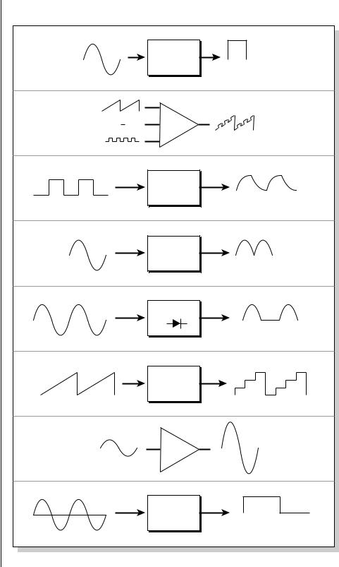
Modulation processors are devices which can modify modulation sources such as LFOs and envelope generators before they are applied to a destination. The modulation processors allow you to create patches and do tricks which would not be possible otherwise. The following modulation processors are currently implemented:
Switch |
Outputs a digital “1” when the input is greater than |
|
“0”. |
Summing Amp |
Allows you to mix several modulation signals |
|
together before applying them to a destination. |
|
This saves cords when the output is to be routed to |
|
multiple destinations. |
Lag Processors |
Slows down rapid changes in the input signal. |
|
The output “lags” behind the input at a |
|
programmed rate (set in the LFO 2 screen). |
Absolute Value |
This function inverts negative values presented to it |
|
and leaves positive values alone. This device outputs |
|
only positive values. |
Diode |
This function only allows positive values to pass and |
|
blocks negative values. |
Flip-Flop |
The output of this processor alternates between a |
|
digital “1” and digital “0” each time the input goes |
|
positive from zero or a negative value. If an LFO |
|
wave were input, the output would be a square wave |
|
of half the input frequency. |
Quantizer |
With the input cord set to 100%, the output value is |
|
limited to 16 discrete values (If the input = sawtooth |
|
wave, then the output = staircase). The value of the |
|
input cord controls the number of steps. The value |
|
of the output cord controls the size of the steps. |
4x Gain |
This processor multiplies the input value by 4 to |
|
amplify modulation sources. |
|
|
EOS 4.0 Software Manual 263
8 - Preset Edit
Modulation Processors
Modulation Processors
|
|
Switch |
|
|
|
|
(above zero) |
|
|
|
DC |
Sum |
|
|
|
|
Lag |
|
|
|
|
Processor |
|
|
|
|
Absolute |
|
|
|
|
Value |
|
|
|
|
Diode |
|
|
|
# of |
|
Size of |
|
|
Steps |
|
Steps |
|
|
|
Quantizer |
|
|
|
|
4x |
|
|
|
|
Gain |
|
|
x |
y |
Flip-Flop |
x |
y |
|
|
264 E-MU Systems
8 - Preset Edit
Modulation Processors
Modulation processors are inserted into a modulation routing as shown in the following diagram.
The modular analog synthesizers of yesteryear were incredibly flexible, partly because processing devices could be connected in any order. Modulation processors are designed according to this modular concept. They can be linked and used in a wide variety of ways limited only by your imagination. Consider the following example:
Velocity ~ |
Switch |
Pitch |
|
Cord |
Cord |
|
Switch On when |
Switch value |
|
Velocity > 0 |
is Scaled by |
|
|
Cord Amount |
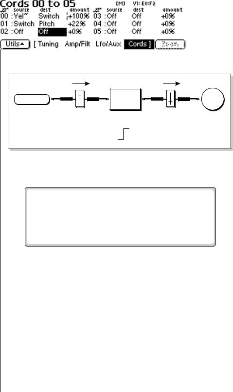
This patch would be programmed in the Cords screen as shown in the following illustration.
This particular patch shifts the overall pitch up a fifth when the key velocity exceeds 64. Velocities below 64 will play at normal pitch and velocities of 64 and above will be raised a perfect fifth. The Velocity “~” source scales the played velocity around zero. In other words, low velocities (below 64) will have negative values and high velocities (64 and above) will be positive. A velocity of 64 would be zero. The Switch module only outputs a “1” if the input value is greater than zero. This digital “1” value can be scaled through the attenuator on the cord to raise or lower the pitch by any amount. In this case, a scaling value of +22 raises the pitch by a perfect fifth. The amount of the patchcord on the input to the switch is unimportant because ANY velocity value equal or greater than 64 will flip the switch. If the input cord amount were a negative value however, the action of the velocity would be reversed and velocities less than 64 would raise the pitch and velocities equal or greater than 64 would play the original pitch.
But what if you wanted the velocity switch point to be something other than 64? Thanks to the modulation processors, it can be done. Here's how.
EOS 4.0 Software Manual 265
8 - Preset Edit
Modulation Processors
Velocity ~
Cord
21
DC
Cord
Switch |
Switch On when Velocity > 0
Pitch
Cord
Switch value is Scaled by Cord Amount
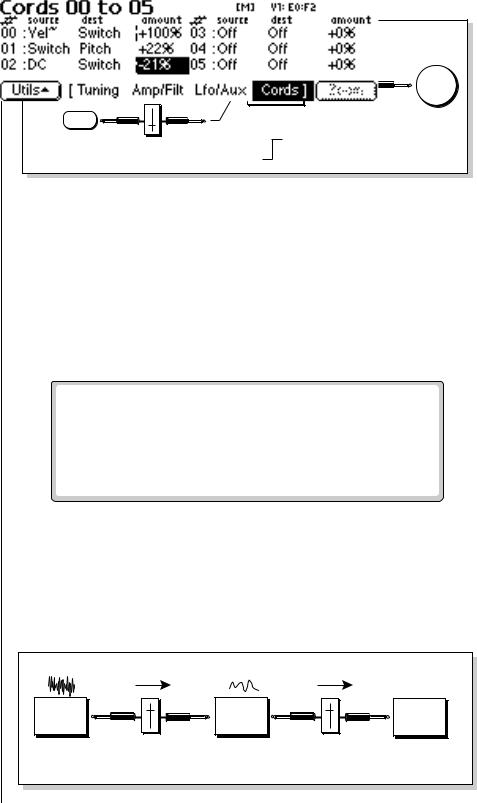
1.Connect the DC level to the input of the switch along with the velocity value. Note that more than one modulation source can be applied to the input of a processor.
The value of the DC offset determines the velocity switch point and is adjusted using the patchcord's attenuator.
2.Set the DC amount to a negative amount, higher velocity values are required to trip the switch. Setting the DC value to a positive value brings the velocity switch point down.
Following is the Cords screen for this patch.
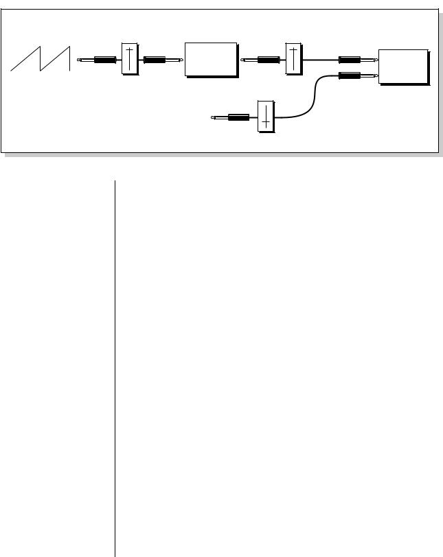
Another example routes the Pink Noise generator through one of the Lag Processors in order to derive a smooth random function. A smooth random wave is useful in small amounts to add a degree of natural variation to timbre when routed to filter cutoff. Normal pink noise is low pass filtered audio frequency noise with a 3 dB/octave slope to give equal energy per octave. Our pink noise is actually more like very low frequency filtered (mauve) noise, but it is perfect for use as a random control source.
Pink |
Lag |
Filter |
Noise |
Processor |
Cutoff |
|
Cord |
Cord |
|
Lag Smooths |
Smooth |
|
Pink Noise |
Random Function |
266 E-MU Systems
8 - Preset Edit
Modulation Processors
O The 4x Amp can be used to get more steps or increase the interval of the quantizer.
O Experiment with this patch by connecting other sources and destinations to the quantizer.
The Quantizer can generate interesting whole-tone scales when envelope generators or LFOs are routed to the input. The quantizer turns a smoothly changing input signal into a series of steps. By routing the output of the quantizer to Pitch and adjusting the cord amounts, you can control both the number of steps and the pitch interval of each step.
Number |
Size |
of |
of |
Steps |
Steps |
|
Quantizer |
Cord |
Cord |
The input cord amount controls how many steps are generated. A sawtooth wave (LFO+) feeding the input, and the cord amount set to 100% generates sixteen steps. The output cord amount controls the size (or interval) of the steps.
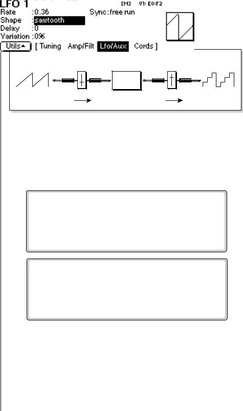
Try setting up the following patch exactly as shown below using your favorite preset as a starting point.
This patch generates an ascending arpeggio every time you press a key. The block diagram of the patch is shown on the following page. The patch is very straightforward except for the DC offset which was added in to bring the pitch down into tune. (Sometimes you have to fix a problem, but using the mod processors there's usually a way around it to achieve the desired result.)
EOS 4.0 Software Manual 267
8 - Preset Edit
Modulation Processors
LFO+ |
Number |
Size |
100% |
100% |
|
|
|
Quantizer |
|
|
Pitch |
|
Cord |
Cord |
|
|
Cord |
|
|
DC |
|
|
-50% |
You can probably start to see some of the possibilities (and there are many). Whenever you find yourself wishing for some esoteric type of control, take a minute and think if there is a way to achieve the desired result using the modulation processors.
268 E-MU Systems