

- •Contents
- •Introduction
- •Introduction
- •Important Upgrade Information
- •About EOS
- •Graphic User Interface
- •Sequencer and Data Filer
- •Sound Libraries
- •Sound Storage
- •Advanced DSP
- •Built-in Digital Effects
- •More Digital Processing Features
- •Power Up!
- •Loading a Bank from the Hard Disk
- •Loading SoundSprints
- •Selecting Presets
- •Lock Button
- •Saving
- •Arpeggiator
- •Keyboard Modes
- •Whole
- •Layer
- •Split
- •Multi
- •The Basics
- •How Sounds are Organized
- •The Sample
- •Voices
- •The Preset
- •SoundSprint
- •Bookmarks
- •The Bank
- •Folders
- •The Internal Drive
- •To Update the EOS Software:
- •External Drives
- •Sample Memory & Preset Memory
- •Sound ROM & Sound RAM
- •Five Types of Memory
- •Flash Sound RAM
- •Sample Numbers
- •Using Preset Flash Memory
- •Using Sound Flash Memory
- •Modules
- •Saving
- •Default
- •Icons
- •The Cursor
- •Data Entry Control & Increment/Decrement Buttons
- •Selecting
- •Using The Browser
- •Guided Tours
- •Banks, Sequences, Presets & Samples
- •Loading a Bank Automatically
- •Loading a Sequence from a Different Bank
- •Loading Standard MIDI Files
- •Saving Banks
- •Finding Banks, Presets, Samples & Sequences
- •Naming Banks
- •Erasing Banks
- •Assignable Keys
- •Recording a Sequence
- •Arpeggiator Sequencing!
- •A Practice Sampling Session
- •Exploring the Preset
- •Which Voices are Assigned to the Keyboard?
- •Creating a Link
- •Master Menu
- •Overview
- •Memory Statistics
- •Master Utilities
- •Assignable Keys
- •Channel Volume
- •Tones
- •Recalibration
- •Test Access
- •About…
- •Bank
- •Erase Bank
- •Name Bank
- •Auto Bank Load
- •Flash Utilities
- •Using Sound Flash Memory
- •Erase the Bank
- •Load the Bank you Wish to Save to Flash
- •Save the Sounds to Flash
- •Mount the Drive
- •Erase the Bank…again
- •Erase Preset 000
- •Merge the Presets
- •Save the Presets
- •Setup
- •Tune
- •Tuning Offset
- •Transpose
- •Audition Key
- •Input/Output
- •Headroom
- •Output Boost
- •Output Format
- •ADAT Output Dither
- •Default Clock
- •Word Clock In
- •WC Phase In/Out
- •Miscellaneous
- •Contrast
- •Wrap Field Selection
- •Screen Saver
- •Disable Sound ROM
- •Zero Crossing Threshold
- •Background
- •Undo/Redo Enable
- •SCSI/Disk
- •SCSI ID
- •SCSI Termination On/Off
- •Avoid Host on ID
- •Disk Button Goes To:
- •Import Options
- •Master Effects
- •Use Master Effects Settings in MultiMode
- •Master Effects A
- •A EFFECT TYPES
- •Master Effects B
- •B EFFECT TYPES
- •Effects Setup
- •Effects Control
- •Sequence Manage
- •MIDI
- •MIDI Mode
- •Basic Channel
- •MIDI Mode
- •MIDI Device ID
- •Local Control
- •Multimode - MIDI Mix
- •MIDI Controllers
- •About MIDI Controllers
- •MIDI Preferences
- •Velocity Curve
- •Controller #7 Sensitivity
- •Controller #7 Curve
- •Global Pedal Override
- •Receive Program Change On/Off
- •Send Program Change On/Off
- •Magic Load Preset
- •Effects
- •Effects
- •Dual Effects Processor
- •The Effects Sends
- •Effect B Into Effect A
- •Three-way Effects Control
- •Effects Programmed in the Preset
- •Master Effects
- •Using Master Effects Settings in Multimode
- •Using the Effects Channel Settings in Multimode
- •Effects Bypass
- •Effect Descriptions
- •A EFFECT TYPES
- •B EFFECT TYPES
- •Reverb
- •General Descriptions of Reverb
- •Chorus
- •Doubling
- •Slapback
- •Stereo Flanger
- •Delay
- •Stereo Delay
- •Panning Delay
- •Dual Tap
- •Vibrato
- •Distortion
- •Sequencer
- •Sequence Manage
- •Recording MIDI SysEx
- •Important Information for Loading Standard MIDI Files
- •Name Sequence
- •Export
- •Transport Controls
- •Sequencer Utilities
- •Erase
- •Copy Sequence
- •Sequencer Memory
- •Jukebox
- •Sequence Edit
- •The Sequence Edit Screen
- •Track Mode
- •Track Numbers
- •Counter Display
- •Tempo Display
- •MIDI Channel Modes
- •Volume - Pan - Submix
- •The Initial Track State Screen
- •Initial Tempo
- •Editing: Cut, Copy & Paste
- •Cut/Copy/Erase
- •Note Erase
- •Erase
- •Delete
- •Paste
- •Insert
- •Replace
- •Track Delete
- •Track Copy
- •UNDO! (REDO!)
- •Tools
- •Quantize
- •Quantize -1/4 Note
- •Quantize - 8th Notes, Swing 60%
- •Quantize - 8th Notes, Swing 67%
- •Quantize - 8th Notes, Swing 75%
- •Transpose
- •Sequence Velocity
- •Channelize
- •Channel Extract
- •Setup
- •Metronome
- •Sequence Clock
- •Sequence Input
- •Sequence Record
- •Start Record -
- •Count In
- •Sequence Loop
- •Transport
- •Track Status Options:
- •Received MMC Commands
- •Locate
- •Sample Manage
- •Overview
- •Sample Utilities
- •Erase Sample
- •Copy Sample
- •Sample Dump
- •Defragment Memory
- •Name Sample
- •New Sample
- •Threshold
- •Input Channels
- •Sampling Source & Rate
- •Dither
- •ADC Gain
- •Sample Length
- •Arm Sample Trigger
- •Force Sample Trigger
- •Keyboard Sample Trigger
- •Monitor On/Off
- •Automatic Parameters
- •Automatic Digital Signal Processing Operations
- •Auto-Placement Parameters
- •Place Sample
- •Export Sample
- •Get Info
- •Sample Edit
- •Sample Edit
- •Background: The Scrub Wheel
- •Background: Using Cut, Copy, Paste and Undo
- •Undo and Redo
- •Typical Applications
- •Background: About Looping
- •How Looping Works
- •Auto Correlation
- •Creating Attack & Decay Characteristics for the Looped Portion
- •Loop Compression
- •Crossfade Looping
- •Zero Crossing
- •Utilities
- •Cut Section
- •Copy Section
- •Paste Section
- •Truncation
- •Taper
- •Tools 1
- •Loop
- •Loop Type
- •Digital Tuning
- •Sample Rate Convert
- •Sample Calculator
- •Tools 2
- •DC Filter
- •Swap Left & Right
- •Stereo <-> Mono
- •Reverse Section
- •Sample Integrity
- •Tools 3
- •Gain Change
- •Compressor
- •Mode
- •Threshold
- •Compression Ratio
- •Attack Time
- •Release Time
- •Using the Digital Compressor
- •Limiter
- •Musical Compression (e.g. Guitar)
- •Noise Reduction
- •Parametric Equalizer
- •FIR (Phase Linear Filter)
- •Aphex Aural Exciter
- •Tools 4
- •Transform Multiplication
- •Doppler
- •Time Compression
- •Pitch Change
- •Bit Converter
- •Beat Munger
- •Beat Munger Controls
- •Undo
- •Preset Manage
- •Preset Manage
- •Utilities
- •Erase Preset
- •Dump Preset
- •Name Preset
- •New Preset
- •Copy Preset
- •Export Preset
- •Get Info
- •Preset Edit
- •Synthesizer Basics
- •Editing Presets
- •Modulation
- •Modulation Sources
- •Keyboard Key
- •Key Velocity
- •Release Velocity
- •Gate
- •Key Glide
- •Pitch and Mod Wheels
- •Keyboard Pressure (mono aftertouch)
- •Pedal
- •Miscellaneous Controllers A -H
- •Low Frequency Oscillators (2 per voice)
- •Envelope Generators (3 per voice)
- •Noise & Random Generators
- •Thumby Button and Footswitches
- •Modulation Cords
- •Envelope Generators
- •Low Frequency Oscillators (LFOs)
- •Random Sources
- •Clock Modulation
- •Syncing an LFO to the Clock
- •Modulation Destinations
- •Modulation Processors
- •Modulation Processors
- •Dynamic Filters
- •Dynamic Filters
- •What is a Filter?
- •Parametric Filters
- •The Z-Plane Filter
- •Selecting Voices, Samples & Groups
- •Selecting from the Preset Editor Windows
- •Selecting All Voices
- •Selecting Voices from the Dynamic Processing Level
- •Selecting Voices from the Voice Select Screen
- •Groups
- •Preset Editor
- •PRESET EDIT - Global
- •Global Editor
- •Edit All
- •Preset Effects A
- •Effects Programmed in the Preset
- •Effect
- •A EFFECT TYPES
- •Decay Time
- •HF Damping
- •FX Amounts
- •FX B Through FX A
- •Preset Effects B
- •Effect B
- •B EFFECT TYPES
- •Feedback Amount
- •LFO Rate
- •Delay Time
- •FX Amounts
- •Preset Edit - Links
- •Main Controls
- •Link Type
- •Link Volume
- •Link Pan
- •Link Transpose
- •Link Fine Tuning
- •Link Utilities
- •New Link
- •Copy Link
- •Delete Link
- •Subsume Link
- •Links - Key Window
- •Key Window Controls
- •Keyboard & Velocity Ranges
- •Links - Velocity Window
- •Velocity Window Controls
- •Velocity Range
- •Links - MIDI Filters
- •MIDI Filter Window Controls
- •Preset Edit - Voices
- •Voices - Main Controls
- •Voice Utilities
- •New Voice
- •Copy Voice
- •Delete Voice
- •Split Voice
- •Solo Voice
- •Sample Zone
- •New Sample Zone
- •Get Multisample
- •Delete Sample Zone
- •Combine
- •Expand...
- •Voices - Key Window
- •Key Window Controls
- •Keyboard Ranges
- •Voices -Velocity Window
- •Velocity Window Controls
- •Velocity Range
- •Voices - Realtime Window
- •Realtime Window Controls
- •Preset Edit - Dynamic Processing Level
- •Utilities
- •Voice Select
- •Function Keys
- •The Isolate Key:
- •Copy Voice(s)
- •Delete Voice(s)
- •Automatic Voice Selection
- •WARNING!
- •Solo Voice
- •Key Transpose
- •Coarse Tuning
- •Fine Tuning
- •Non-transpose Mode
- •Chorus Amount
- •Delay
- •Start Offset
- •Glide Rate & Curve
- •Solo Modes
- •Latch Mode
- •Assign Group
- •Filter Parameters
- •FILTER TYPES
- •2-Pole Lowpass
- •4-Pole Lowpass
- •6-Pole Lowpass
- •2nd Order Highpass
- •4th Order Highpass
- •2nd Order Bandpass
- •4th Order Bandpass
- •Contrary Bandpass
- •Swept EQ, 1-octave
- •Swept EQ, 2->1-octave
- •Swept EQ, 3->1-octave
- •Phaser 1
- •Phaser 2
- •Bat Phaser
- •Flanger Lite
- •Vocal Ah-Ay-Ee
- •Vocal Oo-Ah
- •Dual EQ Morph
- •2EQ + Lowpass Morph
- •2EQ Morph + Expression
- •Peak/Shelf Morph
- •Filter Envelope
- •LFO/Auxiliary Envelope
- •Lag Processors
- •Auxiliary Envelope
- •Cords
- •Sample Retrigger
- •Disk Menu
- •Disk Menu
- •Disk Browser
- •Disk
- •Disk Utilities
- •Mount Drives
- •Copy System
- •Format Disk
- •Low Level Format
- •Backup
- •Load Bank
- •Note:
- •Save Bank
- •View…
- •Info, Lock Drive, & Sleep
- •Lock
- •Sleep
- •Folder Utilities
- •Delete
- •Rename
- •Find…
- •View
- •Info…
- •Bank
- •Bank Utilities
- •Delete
- •Name
- •Find…
- •Load Bank
- •Save Bank
- •View
- •Info…
- •Preset
- •Preset Utilities
- •Soundsprint™
- •Bookmarks
- •Find…
- •Load Preset
- •View
- •Info…
- •Sample
- •Sample Utilities
- •Find...
- •View
- •Load Sample
- •Load .WAV & AIFF Files
- •Audition
- •Info…
- •Sequence
- •Sequence Utility
- •Find…
- •View
- •Load Sequence
- •Info…
- •Important Information for Loading Standard MIDI Files
- •Appendix
- •SCSI
- •Why Use SCSI?
- •The SCSI Bus
- •ID Numbers
- •Types of SCSI Cables
- •Terminating SCSI Cables
- •SCSI Problems
- •Sample Transfers Via SMDI
- •Using Multiple Samplers on the SCSI Bus
- •MIDI
- •MIDI Implementation Chart
- •Notes:
- •Index
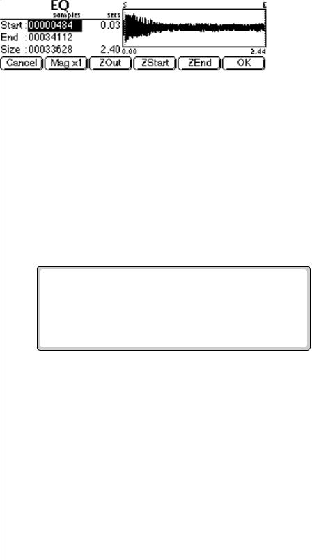
6 - Sample Edit
Parametric Equalizer
O The Start and End points |
Parametric Equalizer |
Parametric EQ allows you adjust the individual parameters of the filter. |
|
are “remembered” from module |
Boost/Cut controls “how much” of the signal will be boosted or cut. Center |
to module so that you can |
Frequency sets the center frequency to be boosted or cut, and the |
perform successive operations |
Bandwidth control sets the width of the band to be boosted or cut. The |
on the same section of the |
three parameters are diagrammed on the following page. |
sample. |
The parametric equalizer is a digital (non real-time) equivalent of an analog |
|
|
|
equalizer with +12 dB of boost and a whopping -48 dB of cut. Center |
|
frequency and bandwidth controls are accurate, precise and have an excep- |
|
tionally wide range. |
OThe left and right cursor v To Filter a Sample:
buttons will change the start |
1. |
Press the Sample Edit key. The LED illuminates and the main sample |
|||
and end points so that they fall |
|||||
|
edit screen appears. |
||||
on positive zero-crossing points |
|
||||
2. |
Select the sample that you want to equalize using the Data Entry |
||||
in the waveform. This will |
|||||
minimize clicks in the sound |
|
Control, INC/DEC keys, or the numeric keypad. |
|||
when processing only part of a |
3. |
Press the Tools 3 function key (F4). Another row of function keys |
|||
sample. |
|
appears. |
|||
|
4. Press the ParEQ function key (F3). The following screen appears. |
||||
|
|
|
|
|
|
|
|
|
|
|
|
OIf the sample is stereo, a • The Select Section display controls are identical to the controls in
pop up dialog box will ask you |
Truncate. See Truncate for a full description of the controls. |
to select left, right or both sides. |
5. Specify the Start and End points for the portion of the sample to be |
|
|
|
EQ'ed using the Data Entry Control, left/right cursor keys, INC/DEC |
O Holding down the Enter |
keys or the numeric keypad. |
6. Press OK to continue on to the next page of options or Cancel to cancel |
|
key while turning the Data Entry |
the operation. |
Control allows “fine tuning” of |
|
the value by one number per |
|
click. |
|
EOS 4.0 Software Manual 225
6 - Sample Edit
Parametric Equalizer
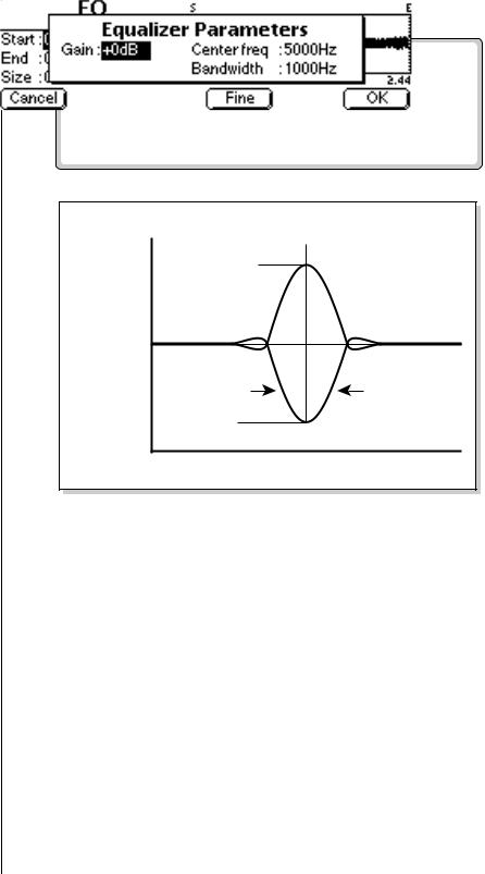
O A standard analog parametric equalizer may be useful in order to locate the frequencies which need EQ. The digital EQ can then be used to actually filter the sample with ultra-low noise and phase linear response.
If you pressed OK, the parametric equalizer parameters are displayed.
+12 dB |
Freq. |
|
|
|
Boost |
Amplitude |
Bandwidth |
|
0 dB |
|
Cut |
|
-48 dB |
Frequency
•Gain: Controls “how much” boost or cut will be applied to the signal.
•Center Frequency: Selects the center frequency to be boosted or cut.
•Bandwidth: Sets the width of the band to be boosted or cut.
7.Specify the parametric equalizer parameters using the Data Entry Control or the INC/DEC keys.
•Coarse/Fine: Fast forward through the values using Coarse, then switch to Fine for single digit editing.
8.Press OK to process the sample section or Cancel to cancel the operation.
226 E-MU Systems
6 - Sample Edit
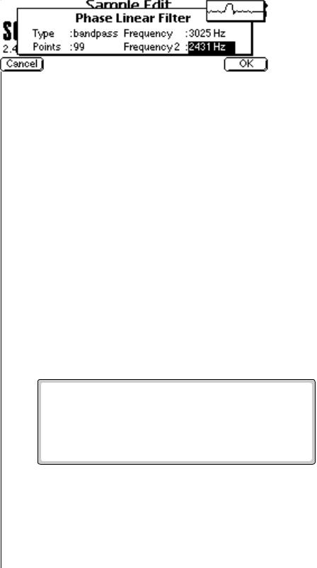
FIR (Phase Linear Filter)
O Holding down the Enter key while turning the Data Entry Control allows “fine tuning” of the value by one number per click.
FIR (Phase Linear Filter)
The phase linear filter was originally developed on the EIII to separate the attack and sustain portions of piano samples. Ordinary filters cause serious phase distortion at the cutoff point. This FIR filter has much less phase distortion than a typical filter and so is better suited for sample splicing. The phase linear filter acts on the ENTIRE sample, unlike the parametric filter which can filter any portion of the sample. This ensures strict phaselinearity. There are five types of phase linear filters available: Lowpass,
Highpass, Bandpass, Allpass and Notch.
The Points parameter determines the Quality or Q of the filter. The larger the Point value, the more the filter behaves like an ideal filter and the steeper the filter slope. The Points parameter is variable from 5 to 99.
The Frequency parameter determines the cutoff frequency of the filter and is calibrated in Hertz. When Bandpass or Notch filters are selected, a second frequency field appears to allow you to specify the frequencies on either side of the passband or notch.
The Allpass filter is a special purpose filter that is used to add delay to a sample before it is recombined with a filtered sample. Recombining allows you to perform band-splitting or frequency boosting instead of frequency attenuation.
v To Filter a Sample:
1.Press the Sample Edit key. The LED illuminates and the main sample edit screen appears.
2.Select the sample that you want to equalize using the Data Entry Control, INC/DEC keys, or the numeric keypad.
3.Press the Tools 3 function key (F4). Another row of function keys appears.
4.Press the FIR function key (F4). The following screen appears.
5.Select the filter Type: Lowpass, Highpass, bandpass, Notch or Allpass.
6.Set the filter slope by adjusting the Points parameter. The higher the number, the steeper the filter slope.
7.Set the Frequency parameter to the desired frequency. If you chose the Bandpass or Notch filters, the Frequency 2 field will appear, allowing you to set the lower frequency in the range.
8.Press OK to filter the sample or Cancel to cancel the operation.
EOS 4.0 Software Manual 227
6 - Sample Edit
FIR (Phase Linear Filter)
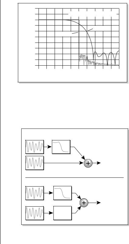
• Alternate Filter Responses
Low Shelving Boost - Add Lowpass with original signal.
High Shelving Boost - Add Highpass with original signal.
Band Boost - Add Bandpass with original signal.
|
+20dB |
|
|
|
|
|
|
|
|
|
|
|
+10dB |
|
|
|
Filter Size and Slope |
|
|||||
|
0dB |
|
|
|
|
|
|
|
|
|
|
Attenuation |
-10dB |
|
|
|
|
|
|
5 points |
|
|
|
-20dB |
|
|
|
|
|
|
|
|
|||
|
99 points |
|
|
|
|
|
|
|
|||
-30dB |
|
|
|
|
|
|
|
|
|||
|
|
|
|
|
|
|
|
|
|
||
-40dB |
|
|
|
|
|
|
|
|
|
|
|
-50dB |
|
|
|
|
|
|
|
|
|
|
|
|
|
|
|
|
|
|
|
|
|
|
|
|
-60dB |
|
|
|
|
|
|
|
|
|
|
|
-70dB |
|
|
|
|
|
|
|
|
|
|
|
-80dB |
|
|
|
|
|
|
|
|
|
|
|
0 |
0.1 |
0.2 |
0.3 |
0.4 |
0.5 |
0.6 |
0.7 |
0.8 |
0.9 |
1 |
|
|
|
|
Frequency |
(rad x pi) |
|
|
|
|||
This chart shows the relationship between the filter Points and Slope.
The Allpass filter can be used to achieve complex formants, notches or frequency boosts by copying, filtering and adding the original sample to the filtered version. When adding filtered signals with the FIR, each signal must be processed through the same number of points to preserve phaselinearity. The diagram below shows the incorrect and correct ways to add signals together.
|
Creating a Low Frequency Boost EQ |
Sample |
Low Pass |
|
50 Pts. |
|
Sum |
Copy of |
Signals Add |
Sample |
Out of Phase |
Sample |
Low Pass |
Sum |
|
50 Pts. |
|
|
|
Copy of |
All Pass |
|
Sample |
||
50 Pts. |
||
|
Signals Add
In Phase
The signal is passed through the Phase-linear filter and recombined with the original signal to create a low frequency boost. Because of the filtering, the two signals are now out of phase. The Allpass filter, set to the same point size, is used to correct the problem.
228 E-MU Systems