

2 - Master Menu
Input/Output
The raw sample (at the original pitch) will be played if you audition from any samplerelated screen (Sample Manage, Sample Edit, Disk Sample Browser).
Suggested
Settings
Polyphonic Music
Boost = 0
Headroom = 3
Single Sample Digital Transfer
Boost = +12 Headroom = 6 to 8
Audition Key
This parameter lets you set the key that will be played when the front panel Audition Key is pressed, or the ASCII keyboard controlled audition command (Control, A) is applied.
v To Change the Audition Key:
1.Press the Master button. The LED illuminates and the Memory Statistics screen appears.
2.Press the Setup function key (F3). A second row of function keys appears.
3.Press the Tune function key (F1). The Tuning screen appears.
4.Move the cursor to the Audition Key field using the cursor buttons or by pressing the F3 button.
5.Select the Audition Key using the Data Entry Control, INC/DEC buttons or the keyboard.
6.Press the Exit button twice to return to the Memory Statistics screen.
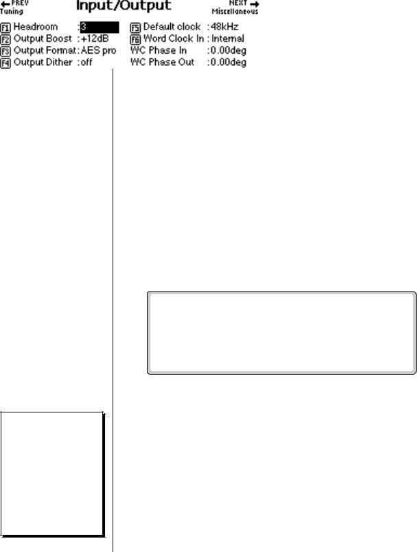
Input/Output
The Input/Output submenu contains functions dealing with the audio and digital outputs.
Headroom
Headroom is the amount of dynamic range remaining before clipping occurs. Think of a tall person (the signal) in a small room. Raising the ceiling increases the headroom or the amount of space between the top of the person's head and the ceiling.
The headroom adjustment, the master volume control, AES Boost and the zone level all control the output level of the digital audio output. These controls can be adjusted when transferring digital audio to optimize the signal level.
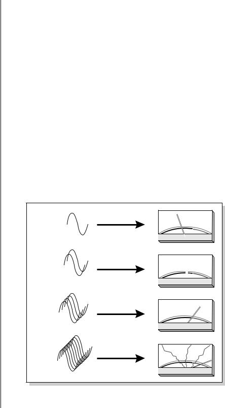
A sampling musical instrument, unlike a CD player, must play multiple channels at once and each additional channel increases the headroom requirement by 3 dB.
80 E-MU Systems
2 - Master Menu
Input/Output
O The headroom adjustment also controls the level of the digital audio output.
The amount of headroom is adjustable from 0 dB to 15 dB in 1 dB increments (with the front panel volume control set to maximum). A headroom setting of 0 dB for example, provides the hottest output level, (and the highest signal to noise ratio) but may produce “clipping” if too many notes are played at once. The default headroom setting is +3 dB, which maintains an excellent signal to noise ratio while keeping a reasonable amount of headroom in reserve. If you hear the signal clipping or breaking up, increase the amount of headroom. The headroom adjustment also controls the level of the S/PDIF digital output. Press Exit after setting the headroom to store the setting in FLASH RAM.
v To Change the Headroom:
1.Press the Master button. The LED illuminates and the Memory Statistics screen appears.
2.Press the Setup function key (F3). A second row of function keys appears.
3.Press the Output function key (F2). The Output menu appears.
4.Advance the cursor to the Headroom field. Adjust the amount of remaining headroom using the Data Entry Control, or INC/DEC buttons.
5.Press the Exit button to return to the Setup screen. Press the Exit button again to return to the Memory Statistics screen.
x1 |
- |
|
10 |
7 |
5 |
3 |
1 |
0 |
1 |
3 |
+ |
|
20 |
4 |
|||||||||
|
|
|
|
VU |
|
|
|
|
|||
x2 |
- |
|
10 |
7 |
5 |
3 |
1 |
0 |
1 |
3 |
+ |
|
20 |
4 |
|||||||||
|
|
|
|
VU |
|
|
|
|
|||
x4 |
- |
|
10 |
7 |
5 |
3 |
1 |
0 |
1 |
3 |
+ |
|
20 |
4 |
|||||||||
|
|
|
|
VU |
|
|
|
|
|||
x8 |
- |
|
10 |
7 |
5 |
3 |
1 |
0 |
1 |
3 |
+ |
|
20 |
4 |
|||||||||
|
|
|
|
VU |
|
|
|
|
|||
The more channels are played, the more headroom is required. Increasing the headroom lets you play more channels without clipping.
EOS 4.0 Software Manual 81
2 - Master Menu
Input/Output
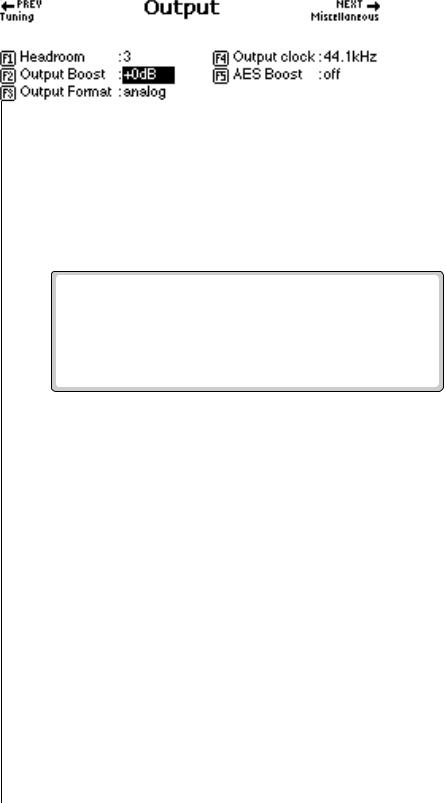
Output Boost
Output Boost is similar to the headroom control and digitally raises the output level by up to +12 dB. This option provides the best signal-to-noise ratio when only one or two channels are being played at a time. However, playing back too many channels with Output Boost turned on may cause the output signal to clip. This control affects both the analog and digital outputs.
v To Change the Output Boost:
1.Press the Master button. The LED illuminates and the Memory Statistics screen appears.
2.Press the Setup function key (F3). A second row of function keys appears.
3.Press the Output function key (F2). The output menu appears.
4.Set the output boost to +0 dB or +12 dB using the Data Entry Control, or INC/DEC buttons.
5.Press the Exit button twice to return to the Memory Statistics screen.
Output Format
The digital audio output (optional on the e-6400) is used for interfacing with other digital or analog audio equipment using either the AES/EBU (professional) or S/PDIF (consumer) formats. The digital audio interface carries two channels of audio information which mirror the audio at the main outputs. The analog and digital outputs are always active. This function optimizes the output for whatever format is being used. Set the Output Format to the digital format you are currently using: S/PDIF or AES pro.
v To Change the Output Format:
1.Press the Master button. The LED illuminates and the Memory Statistics screen appears.
2.Press the Setup function key (F3). A second row of function keys appears.
82 E-MU Systems
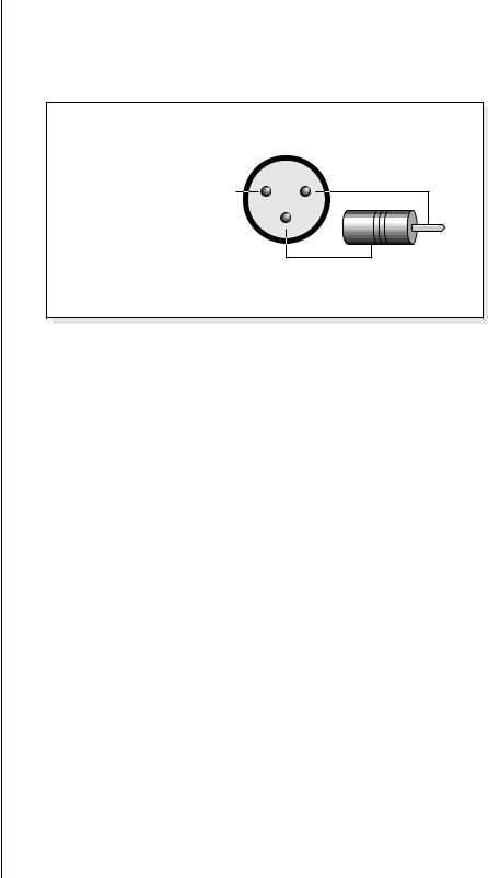
O Always use high-quality, low-capacitance cable for the AES/EBU interface to insure data integrity.
O When to Dither?
Add Dither - When sending ADAT data to a 16 bit device which doesn’t dither at the input.
Don’t Add Dither - When sending ADAT data to a 20-24 bit device.
2 - Master Menu
Input/Output
3.Press the In/Out function key (F2). The output menu appears.
4.Set the output format to S/PDIF, AES pro or Analog using the Data Entry Control, or INC/DEC buttons.
5.Press the Exit button twice to return to the Memory Statistics screen.
|
XLR |
|
|
AES to S/PDIF |
Plug |
|
|
Adapter Cable |
|
2 + |
|
1 |
|
Center Pin |
|
N.C. |
|
|
|
|
3 |
RCA |
|
|
|
|
|
|
- |
Shield |
To |
|
|
S/PDIF |
|
|
|
|
Device |
ADAT Output Dither
Dither is a technique used in digital systems to improve audio performance by adding noise to the least significant data bits. In general, dither is used whenever a digital number is converted to a smaller number (for instance when converting 20 bits to 16 bits).
As an example, suppose you were transferring ADAT optical data from the Ultra to an older ADAT recorder. The ADAT output is 20 bits wide while the older ADAT only receives data 16 bits wide. In this case you would turn Dither On because the receiving device has fewer bits. If you were sending data to a new ADAT which receives 20 bit data, you would turn Dither Off.
v To Turn ADAT Output Dither On or Off:
1.Press the Master button. The LED illuminates and the Memory Statistics screen appears.
2.Press the Setup function key (F3). Another row of function keys appears.
3.Press the In/Out function key (F2). The Input/Output screen appears.
4.Move the cursor to the ADAT Output Dither field using the cursor buttons or by pressing the F4 key.
5.Turn Dither on or Off using the Data Entry Control, or INC/DEC buttons.
6.Press the Exit button twice to return to the Memory Statistics screen.
EOS 4.0 Software Manual 83