

104 F. D. Fragiskos
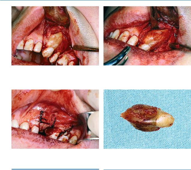
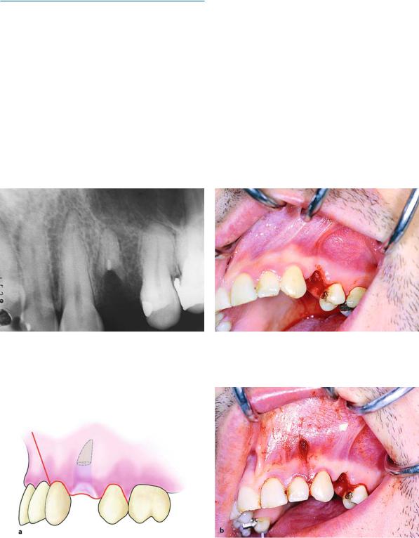
Fig. 6.30. A trapezoidal flap is created, which extends from the lateral incisor as far as the distal aspect of the maxillary first premolar
Fig. 6.32. Operation site after placement of sutures
6.5
Surgical Extraction of Roots
There are various surgical techniques for root removal, as listed below:
ΟRemoval of part of the buccal bone for luxation of the root buccally.
ΟThe opening of a window on the buccal bone for removal of the root through the socket or through the window itself.
ΟCreation of a groove on the surface of the root (to be used as a purchase point for positioning the elevator), after removal of a small amount of buccal bone.
Fig. 6.31. Use of a chisel to remove the tooth, together with the ankylosed portion of the labial plate
Fig. 6.33. Tooth after removal, with a portion of bone on the labial surface
6.5.1
Root Extraction After Removal of Part of the Buccal Bone
When the tooth is single-rooted and the level of the root is below the margin of alveolar bone (Figs. 6.34,
6.35), an L-shaped incision is made (Fig. 6.36), the flap is reflected (Fig. 6.37), and a large part of the buccal bone is removed using a round bur until the root is exposed (Figs. 6.38a, b). The root is then luxated using a straight elevator, which is placed palatally in the gingival sulcus (when it involves the maxilla). The root is mobilized easily, using rotational movements with the elevator and applying a small amount of pressure
ΟCreation of a groove between the root and bone, outwards (Figs. 6.39, 6.40). After smoothing the bone which allows for positioning of the elevator. margins, the surgical field is irrigated with saline solu-
Each of the aforementioned techniques is described in detail below.
tion and, after repositioning the flap, the wound is sutured (Figs. 6.41, 6.42).
Chapter 6 Surgical Tooth Extraction |
105 |
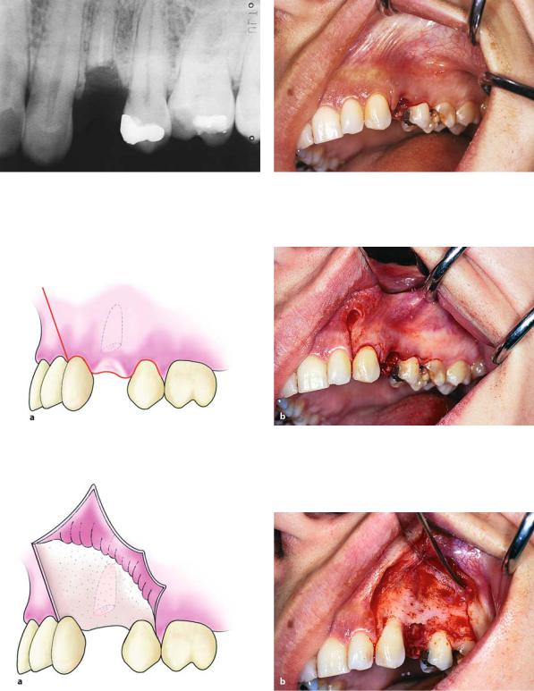
Fig. 6.34. Radiograph of the root of a maxillary first pre- |
Fig. 6.35. Clinical photograph of the case shown in |
molar. The surgical technique is indicated for its removal |
Fig. 6.34 |
Fig. 6.36. Creation of an L-shaped incision, which extends from the mesial aspect of the canine as far as the distal aspect of the second premolar
Fig. 6.37 a, b. Reflection of the flap. a Diagrammatic illustration. b Clinical photograph
106 F. D. Fragiskos
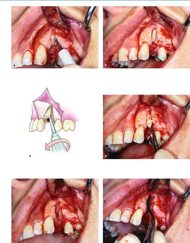
Fig. 6.38 a, b. a Removal of the buccal plate along the length of the root using a round bur. b The root is exposed after bone removal. This technique is employed in cases where ankylosis is present along the entire root surface
Fig. 6.39 a, b. Diagrammatic illustration (a) and clinical photograph (b) of luxation of the root in the outward direction using a straight elevator
Fig. 6.40. Surgical field at the end of the operation |
Fig. 6.41. Smoothing of bone margins of the wound using |
|
a bone file |
Chapter 6 Surgical Tooth Extraction |
107 |
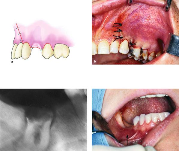
Fig. 6.42 a, b. Operation site after suturing. Diagrammatic illustration (a) and clinical photograph (b)
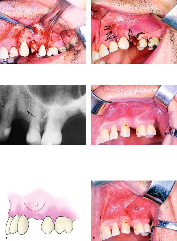
Fig. 6.43. Radiograph of roots of the mandibular first molar. The surgical technique is indicated for their removal
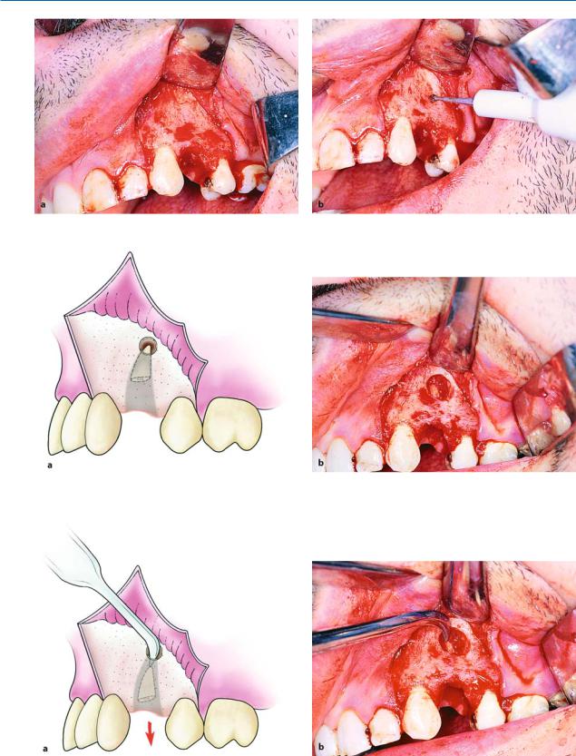
When the tooth has two roots and the roots are below the level of the margin of the alveolar process without being separated (Figs. 6.43, 6.44), the extraction is performed as follows. First an envelope flap is created, one or two teeth at most, beyond the root to be removed (Figs. 6.45 a, b). Then part of the buccal
Fig. 6.44. Clinical photograph of the case shown in Fig. 6.43. The roots are located at the point shown by the arrow
bone is removed using a round bur, until the root bifurcation is exposed. The roots are sectioned using a fissure bur and are removed with a straight elevator
(Figs. 6.46 a, b, 6.47). The socket is then cared for accordingly and sutures are placed.
108 F. D. Fragiskos
Fig. 6.45 a, b. Diagrammatic illustration (a) and clinical photograph (b) showing the creation of an envelope flap to expose the roots
Fig. 6.46 a, b. Diagrammatic illustration (a) and clinical photograph (b) showing the removal of the buccal plate as far as the root bifurcation. Roots are separated using a fissure bur in the buccolingual direction
Fig. 6.47 a,b. Luxation of roots after sectioning. a Diagrammatic illustration. b Clinical photograph
Chapter 6 Surgical Tooth Extraction |
109 |
6.5.2
Extraction of Root after a Window is Created on Buccal Bone
This technique is indicated for the removal of roots immediately after their fracture (Figs. 6.48, 6.49), so that the buccal bone remains intact. The procedure in this case is as follows. After making an L-shaped incision, the flap is reflected and a small window is created, using a round bur, with constant irrigation using saline solution, on the buccal bone, corresponding to the tip of the fractured root (Figs. 6.50–6.52). The window is then enlarged, and enough of the root is exposed to allow its displacement from the socket us-
ing a narrow-angled elevator (Figs. 6.53, 6.54). After removal of the root, the socket is cared for and interrupted sutures are placed (Fig. 6.55).
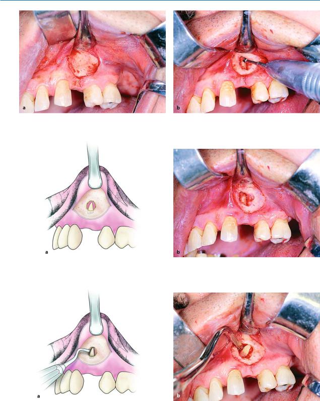
The root may also be removed though the window itself that was created on the buccal bone using the previously mentioned technique. Depending on the case, a trapezoidal or semilunar flap is created and complete or partial exposure of the root follows (Figs. 6.56–6.60). The root is then removed from the bone deficit without difficulty, preferably using a nar- row-angled elevator (Figs. 6.61–6.64). This technique is usually used in cases of fractured small roots, which were not removed during the extraction procedure but remained in the socket for a long time and were eventually totally covered by bone.
Fig. 6.48. Radiograph of the root of a maxillary first premolar. The open window technique on buccal alveolar bone is indicated for its extraction
Fig. 6.49. Clinical photograph of the case shown in Fig. 6.48, immediately after fracture of the root
Fig. 6.50 a, b. L-shaped incision, which extends from the mesial aspect of the canine as far as the distal aspect of the second premolar. a Diagrammatic illustration. b Clinical photograph
110 F. D. Fragiskos
Fig. 6.51 a, b. Reflection of the flap (a) and removal of bone at the apex of the tooth (b)
Fig. 6.52 a, b. Diagrammatic illustration (a) and clinical photograph (b). Removal of bone and part of the apex of the tooth are shown
Fig. 6.53 a, b. Elevator positioned at the tip of the root, which is delivered from the socket. a Diagrammatic illustration. b Clinical photograph
Chapter 6 Surgical Tooth Extraction |
111 |
Fig. 6.54. Final step in root extraction from the socket |
Fig. 6.55. Operation site after placement of sutures |
Fig. 6.56. Periapical radiograph of the root of the maxil- |
Fig. 6.57. Clinical photograph of the case shown in |
lary first premolar. A surgical extraction is indicated due to |
Fig. 6.56 |
complete osseous coverage |
|
Fig. 6.58 a, b. Diagrammatic illustration (a) and clinical photograph (b) of the semilunar incision created between the canine and first premolar
112 F. D. Fragiskos
Fig. 6.59 a, b. Creation of flap (a) and removal of part of the buccal plate (b), corresponding to the area where the root is located
Fig. 6.60 a, b. Diagrammatic illustration (a) and clinical photograph (b) after removal of the buccal plate and exposure of the root
Fig. 6.61 a, b. Removal of the root from the osseous window using double-angled elevator. a Diagrammatic illustration. b Clinical photograph

Chapter 6 Surgical Tooth Extraction |
113 |
Fig. 6.62 a,b. a Surgical field at the end of the operation. b Root after removal
Fig. 6.63. Stabilization of the flap in its initial position with Fig. 6.64. Operation site after suturing placement of the first suture at the center of the semilunar
incision
6.5.3 |
6.5.4 |
Creation of Groove on Surface of Root, |
Creation of a Groove Between Root and Bone, |
after Removal of Small Amount of Buccal Bone |
Which Allows Positioning of the Elevator |
This technique is used for roots beneath the margin of the alveolar process. First, an envelope flap is reflected and a small amount of buccal bone is removed, until part of the root is exposed. A groove is then created on its surface, which serves as a purchase point for positioning of the blade of the double-angled elevator, to luxate the root outwards with appropriate movements
(Fig. 6.65 a, b). This technique is used primarily in the mandible, where the buccal bone, which in this case serves as a fulcrum, is dense and able to withstand applied pressure, as opposed to the maxilla.
This technique is used for the roots of posterior mandibular teeth, where the buccal bone, because of the external oblique ridge, is dense and hard. After reflecting an envelope flap in these cases, a groove is created using a round bur between the buccal bone and the root, which makes enough room to allow for the positioning of the elevator. The blade of the T-shaped elevator or of the Seldin elevator is then seated in the groove, which luxates the root upwards, using the external oblique ridge as a fulcrum (Fig. 6.66 a, b).